
Login

Shoutbox
You must login to post a message.
renatoa
04/14/2024 5:56 AM
TheOtherJim and papajim,
 !
!
!allenb
04/11/2024 6:33 PM
Zemona

renatoa
04/11/2024 9:19 AM
Mrbones and sgupta,  ?
?
?renatoa
04/10/2024 1:09 AM
 , Ed K
allenb
04/09/2024 5:34 PM
TheJak99
Forum Threads
Newest Threads
War on Farmers by Su...Kaleido Roaster PID ...
Green coffee sellers
Wet beans - Estimati...
Skywalker roaster mods
Hottest Threads
| Skywalker roaster... | [292] |
| Skywalker, the AL... | [214] |
| Skywalker Roasts | [94] |
| My first popcorn ... | [47] |
| War on Farmers by... | [39] |
In Memory Of Ginny

Donations
Latest Donations
dmccallum - 10.00
JackH - 25.00
snwcmpr - 10.00
Anonymous - 2.00
Anonymous - 5.00
dmccallum - 10.00
JackH - 25.00
snwcmpr - 10.00
Anonymous - 2.00
Anonymous - 5.00
Users Online
Guests Online: 4
Members Online: 0
Total Members: 8,205
Newest Member: TheOtherJim
Members Online: 0
Total Members: 8,205
Newest Member: TheOtherJim
View Thread
Who is here? 1 guest(s)
 Transparent Fluid Bed Design
|
|
| CK |
Posted on 08/15/2019 1:15 PM
|
|
1/2 Pounder  Posts: 250 Joined: December 07, 2018 |
Quote BrewBoy wrote: Just joined the forum due to this thread. Amazing ingenuity! Thank you CK for all of your generous contributions thus far! Very much looking forward to seeing you V2 design, may I ask how it's coming along? Thanks Brewboy. I'm using the same roaster for the past 7 months, but now, as you can see it is all automated with UNO, TC4, ZCD, and Artisan Roasterscope software. I may create a new video of the whole roast process with this V2 iteration. I'm starting to learn how to PID roast via the ET on this machine, following a desired roast curve for the beans. Each machine has different characteristics for following a bean temp curve based off of ET... Machine design and insulation affects the beans ability to take on heat. V3 may come about next year. |
|
|
|
| CK |
Posted on 11/07/2019 10:15 AM
|
|
1/2 Pounder Posts: 250 Joined: December 07, 2018 |
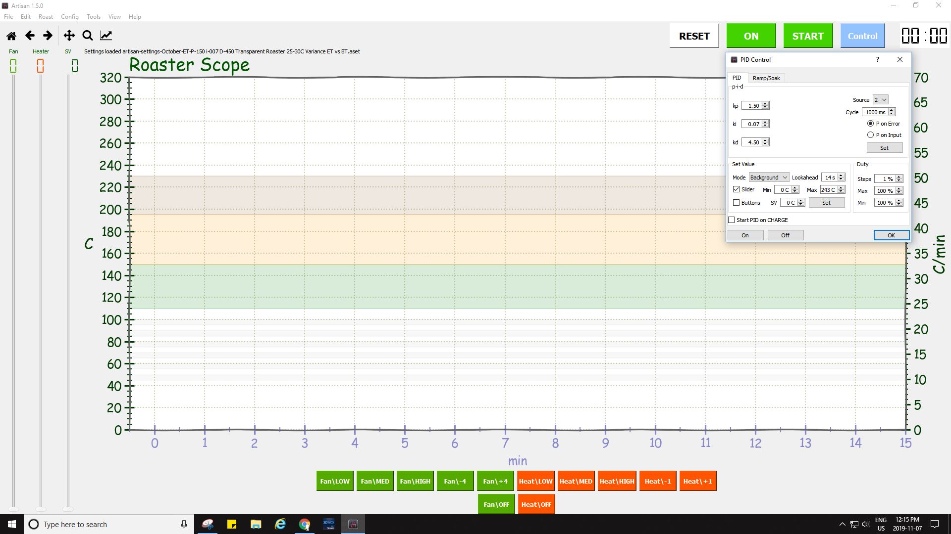
Here's a screenshot of a recent ET PID roast from a couple of weeks ago. The PID follows the profile easily and consistently now. Using the Artisan profile designer, a person can adjust for total time, end temperature desired, and thus affect phase percentages as well. Simply save the generic profile as a template to be used for any bean type you like with that curve and flavor.
CK attached the following image:

|
|
|
|
| CK |
Posted on 11/07/2019 10:37 AM
|
|
1/2 Pounder Posts: 250 Joined: December 07, 2018 |
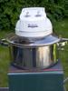
Some people have asked how the carafe was drilled for the RC. Here are some images to show the technique applied.
CK attached the following images:


|
|
|
|
| CK |
Posted on 11/07/2019 12:57 PM
|
|
1/2 Pounder Posts: 250 Joined: December 07, 2018 |
Quote CK wrote: Here's a screenshot of a recent ET PID roast from a couple of weeks ago. The PID follows the profile easily and consistently now. Using the Artisan profile designer, a person can adjust for total time, end temperature desired, and thus affect phase percentages as well. Simply save the generic profile as a template to be used for any bean type you like with that curve and flavor. Here are the settings used for the ET roasting on this machine. (Having issues with images again, I'll keep trying to edit and update with new file names)...
CK attached the following image:
Edited by CK on 11/07/2019 1:35 PM |
|
|
|
| JackH |
Posted on 11/07/2019 3:35 PM
|
 Administrator Posts: 1809 Joined: May 10, 2011 |
The only thing I can suggest about image trouble is to avoid using the post preview, preview reply and watch your filename (avoid Linux reserved characters). I have also had better luck sometimes with .png files.
---Jack
KKTO Roaster. |
|
|
|
| CK |
Posted on 11/07/2019 3:47 PM
|
|
1/2 Pounder Posts: 250 Joined: December 07, 2018 |
Quote JackH wrote: The only thing I can suggest about image trouble is to avoid using the post preview, preview reply and watch your filename (avoid Linux reserved characters). I have also had better luck sometimes with .png files. Thanks Jack. I think the system must buffer in the backend of HR, because after waiting awhile the same image and file name uploaded on another attempt. |
|
|
|
| CK |
Posted on 11/07/2019 3:53 PM
|
|
1/2 Pounder Posts: 250 Joined: December 07, 2018 |
Here is the filter setting screen.
CK attached the following image:

|
|
|
|
| CK |
Posted on 11/24/2019 4:11 PM
|
|
1/2 Pounder Posts: 250 Joined: December 07, 2018 |
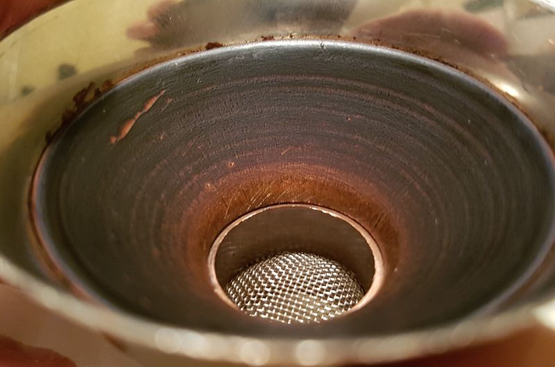
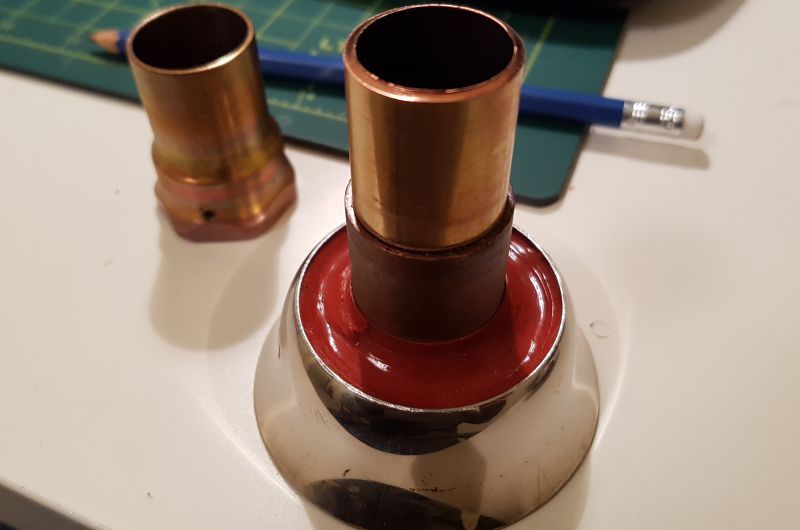
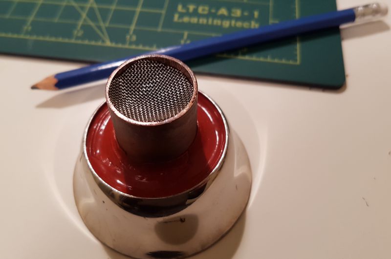
I?ve experimented a little with a perforated plate vs stainless steel mesh for air input on this roaster? the mesh is far superior for unimpeded air flow to loft the beans. This translates into less energy and wear and tear on the blower for any given charge weight. Eg.1 With a 275g charge, the perforated plate required a minimum of 90% power to have any effect on the green beans, and when the heater activates it moves the beans very little, but within about 30-45 seconds the beans are lofting better due to the expansion of heated air (increased CFM) and diminishing moisture content. Eg.2 The same 275g charge is lofted with 60% blower power using the mesh. To see the potential of mesh, I increased the charge weight to 454g and was able to mildly loft beans at 90%. From this, I?ve learned that mesh is more efficient for improving a fluid bed roaster?s loft capabilities. Some builders have struggled with size and quantity of perforations to loft adequately based on perf plate design and their blower of choice. I?m wondering if they have considered mesh? These numbers show that you?ll get more value from a blower if using a mesh for your air inlet at the bottom of your RC. Here are images of the way I was able to install the mesh in 3/4 ? copper pipe.
CK attached the following images:


|
|
|
|
| jbrux4 |
Posted on 11/25/2019 12:43 PM
|
|
1/4 Pounder  Posts: 139 Joined: October 26, 2019 |
Quote CK wrote: I?m wondering if they have considered mesh? These numbers show that you?ll get more value from a blower if using a mesh for your air inlet at the bottom of your RC. CK - In my current build, I specifically designed for a mesh screen. However, with Tr-Clamp fittings, I was limited to an overly expensive high temp gasket with mesh (RubberFab) or to get a filter plate. The cost inhibitor led me to the filter plate option, and it pained me to do so. Perhaps I can try securing just a 20 mesh screen in the heat pipe prior to the roast chamber. My fear is securing it appropriately to restrict failure with the weight of beans during roast, or even at bean charge, initially. Thank you for the results. There was discussion in some other thread about a perf plate providing the turbulence needed to create a fluid-bed. There was no consideration for mesh in that thread though. My intuition told me to put in a mass airflow straightener prior to a mesh screen for as much of a stream of air as possible. I wouldn't want my stream to be turbulent and dissipate. Anyways - my intuition is just that - intuition., Your analysis proves something. Not yet empirical, but definitely something to consider. R/
Jared |
|
|
|
| CK |
Posted on 11/25/2019 1:13 PM
|
|
1/2 Pounder Posts: 250 Joined: December 07, 2018 |
As seen in the above design, the mesh is cut slightly bigger than the inner pipe diameter. When depressed into the pipe it forms a type of dome or arch towards the bean side of the RC, giving good resistance to the weight of any bean charge in this particular case. To secure the mesh it is pinched between a small 3/4" copper ring that was inserted first, then the mesh, then the final bottom pipe was pressed to pinch the mesh in place. When bean weight is on the mesh the force is applied outward to the pipe wall and can not cave in or give way. Perhaps your piping could utilize the same technique with a bushing or fitting cut to your specs. |
|
|
|
| CK |
Posted on 12/02/2019 1:32 PM
|
|
1/2 Pounder Posts: 250 Joined: December 07, 2018 |
An ultra-fast video (10x) of how the transparent roaster now performs using Artisan ET PID settings. The roaster is preheated, and this is the 4th back to back roast for the day. |
|
|
|
| greenthumb |
Posted on 01/03/2020 12:08 PM
|
|
Newbie  Posts: 4 Joined: March 29, 2019 |
CK, I was wondering if the copper intake pipes that bring air from inside the machine terminate at the top or the bottom of the wooden housing? Do you have screens on the intake lines? Thanks! |
|
|
|
| CK |
Posted on 01/03/2020 1:48 PM
|
|
1/2 Pounder Posts: 250 Joined: December 07, 2018 |
I have the 3/4" NPT copper fittings threaded into the top board and they terminate there. There are holes in the bottom board to let air into the chassis to cool components on the way to the intake. There are no screens or filters applied to the intake anymore. The original HEPA filter is removed as it was plugged too easily from high CFM and usage. |
|
|
|
| CK |
Posted on 01/03/2020 2:15 PM
|
|
1/2 Pounder Posts: 250 Joined: December 07, 2018 |
Images of layout.
CK attached the following images:


|
|
|
|
| CK |
Posted on 01/06/2020 12:15 PM
|
|
1/2 Pounder Posts: 250 Joined: December 07, 2018 |
In the name of science and fun, I had to try this... a 276 gram PID controlled popcorn roast, without containment! |
|
|
|
| Rickpatbrown |
Posted on 03/19/2020 1:35 PM
|
|
Newbie Posts: 1 Joined: March 18, 2020 |
Quote CK wrote: In the name of science and fun, I had to try this... a 276 gram PID controlled popcorn roast, without containment! I think you should have let it develope a little longer. Pulling it right at first crack produces a corny flavor. This build is very impressive. I think I might copy it. I've been considering a small sample roaster to quickly evaluate 100gram profiles, so that I can quickly figure out what beans I want to buy. |
|
|
|
| CK |
Posted on 03/19/2020 9:31 PM
|
|
1/2 Pounder Posts: 250 Joined: December 07, 2018 |
Quote Pulling it right at first crack produces a corny flavor. That's funny. Here's a video slowing things down. |
|
|
|
| allenb |
Posted on 03/21/2020 7:39 AM
|
 Administrator Posts: 3858 Joined: February 23, 2010 |
Morning CK I'm really glad you posted that video. I've never seen a slowed down vid of bean spouting to be able to see the actual trajectory they take when moving back into the downward flow. Nice! 1/2 lb and 1 lb drum, Siemens Sirocco fluidbed, presspot, chemex, cajun biggin brewer from the backwoods of Louisiana
|
|
|
|
| CK |
Posted on 03/21/2020 11:59 AM
|
|
1/2 Pounder Posts: 250 Joined: December 07, 2018 |
Thanks Allenb, this action is the result of airflow through the new mesh as seen in post #108. The inlet tube has an area of 23.5% of the roast chamber total area. |
|
|
|
| CK |
Posted on 09/21/2020 10:27 AM
|
|
1/2 Pounder Posts: 250 Joined: December 07, 2018 |
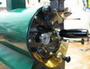
The 2020 industrial iteration of the roaster. This is the first automated roast since applying the new automatic heater safety circuit as noted in this link... https://forum.hom...post_72327 |
|
|
|
| CK |
Posted on 09/21/2020 12:23 PM
|
|
1/2 Pounder Posts: 250 Joined: December 07, 2018 |
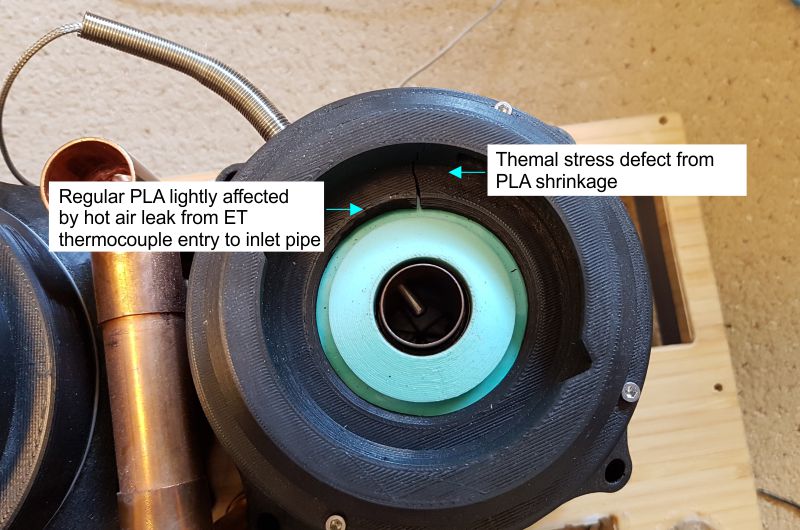
When reconfiguring the build a defect was found on the heater lid part. It still functions well to hold the RC... a high temperature PLA reprint may be made for a fix.
CK attached the following image:
|
|
|
|
| floptronica |
Posted on 10/07/2020 6:41 AM
|
|
Newbie Posts: 2 Joined: October 07, 2020 |
That's a very nice rig you made. I had no idea about the high temp PLA and the gizmo to hear 1st crack better is a new idea to me. So much nicer than holding my ear next to the roast chamber. One Idea i might contribute to your build is to roll your own heating elements. The ones that come with poppers are made with the cheapest possible material, and just don't last too long. Ive been using nichrome 80 in 20 gauge, and an element lasts over a year. Use a knitting needle to roll it. Just get one in the mm diameter of your old coil. |
|
|
|
| CK |
Posted on 10/08/2020 1:47 PM
|
|
1/2 Pounder Posts: 250 Joined: December 07, 2018 |
Thanks for the tips on rolling custom coils and wire choice. That may come in handy in the future if there is need to do repairs. The original coils are still going strong with more than 2 years roasting and testing on them... perhaps because I don't run them maxed out. (They only run at about 50-60% of their potential.) I've simplified the FC sound feature by removing the copper piping, and putting foil directly over the 1" top opening. It's clamped in place with a band clamp over a silicone gasket, keeping the foil relatively flat and stretched tight. The function works just as well as the complicated copper pipe design. |
|
|
|
| TooL |
Posted on 02/07/2021 6:28 AM
|
|
Newbie Posts: 2 Joined: January 17, 2019 |
Hey there, I've been having a peruse through this thread cause this is a really neat design. Have I missed a part list or have you not released one? Just curious as I'm thinking of making a roaster myself and I am curious about how much this kind of setup would cost :) One thing I'm interested in is how it's all powered, do you have a big psu of some sort or is everything just individually plugged into an extension bar or something? Cheers either way as it's been cool to see the idea and progression |
|
|
|
| CK |
Posted on 02/07/2021 11:26 PM
|
|
1/2 Pounder Posts: 250 Joined: December 07, 2018 |
You can refer to posts 21, 23, 42, and 44 for the information. Each 120v power inlet is pulled from a different circuit in the home. |
|
|
|

| Jump to Forum: |
Similar Threads
| Thread | Forum | Replies | Last Post |
|---|---|---|---|
| Coffee Crafters Fluid Bed Coffee Roasters | JAVA TRADING COMPANY | 4 | 03/29/2024 9:41 AM |
| Square tube fluid bed | Fluidbed Roaster | 5 | 02/26/2024 9:32 AM |
| First Fluid bed test..Some success, many questions | MY FIRST ROASTER | 14 | 12/23/2023 11:13 AM |
| Drum or Fluid Bed | Building a Coffee Roaster | 6 | 12/04/2023 1:06 PM |
| Bubblebed roaster based on Nepro wave design | Fluidbed Roaster | 27 | 09/27/2023 3:09 PM |
Powered by PHP-Fusion Copyright © 2024 PHP-Fusion Inc
Released as free software without warranties under GNU Affero GPL v3
Designed with ♥ by NetriXHosted by skpacman