
Login

Shoutbox
You must login to post a message.
renatoa
04/17/2024 9:27 AM
 , branchu
renatoa
04/14/2024 5:56 AM
TheOtherJim and papajim,
 !
!
!allenb
04/11/2024 6:33 PM
Zemona

renatoa
04/11/2024 9:19 AM
Mrbones and sgupta,  ?
?
?renatoa
04/10/2024 1:09 AM
 , Ed K
Forum Threads
Newest Threads
War on Farmers by Su...Kaleido Roaster PID ...
Green coffee sellers
Wet beans - Estimati...
Skywalker roaster mods
Hottest Threads
| Skywalker roaster... | [292] |
| Skywalker, the AL... | [214] |
| Skywalker Roasts | [94] |
| My first popcorn ... | [47] |
| War on Farmers by... | [39] |
In Memory Of Ginny

Donations
Latest Donations
dmccallum - 10.00
JackH - 25.00
snwcmpr - 10.00
Anonymous - 2.00
Anonymous - 5.00
dmccallum - 10.00
JackH - 25.00
snwcmpr - 10.00
Anonymous - 2.00
Anonymous - 5.00
Users Online
Guests Online: 3
Members Online: 0
Total Members: 8,208
Newest Member: branchu
Members Online: 0
Total Members: 8,208
Newest Member: branchu
View Thread
Who is here? 1 guest(s)
Page 2 of 2: 12
|
 Fully Integrated ESP32 Coffee Roast Controller
|
|
| ahardinger |
Posted on 03/13/2018 3:28 AM
|
 Newbie  Posts: 25 Joined: March 03, 2018 |
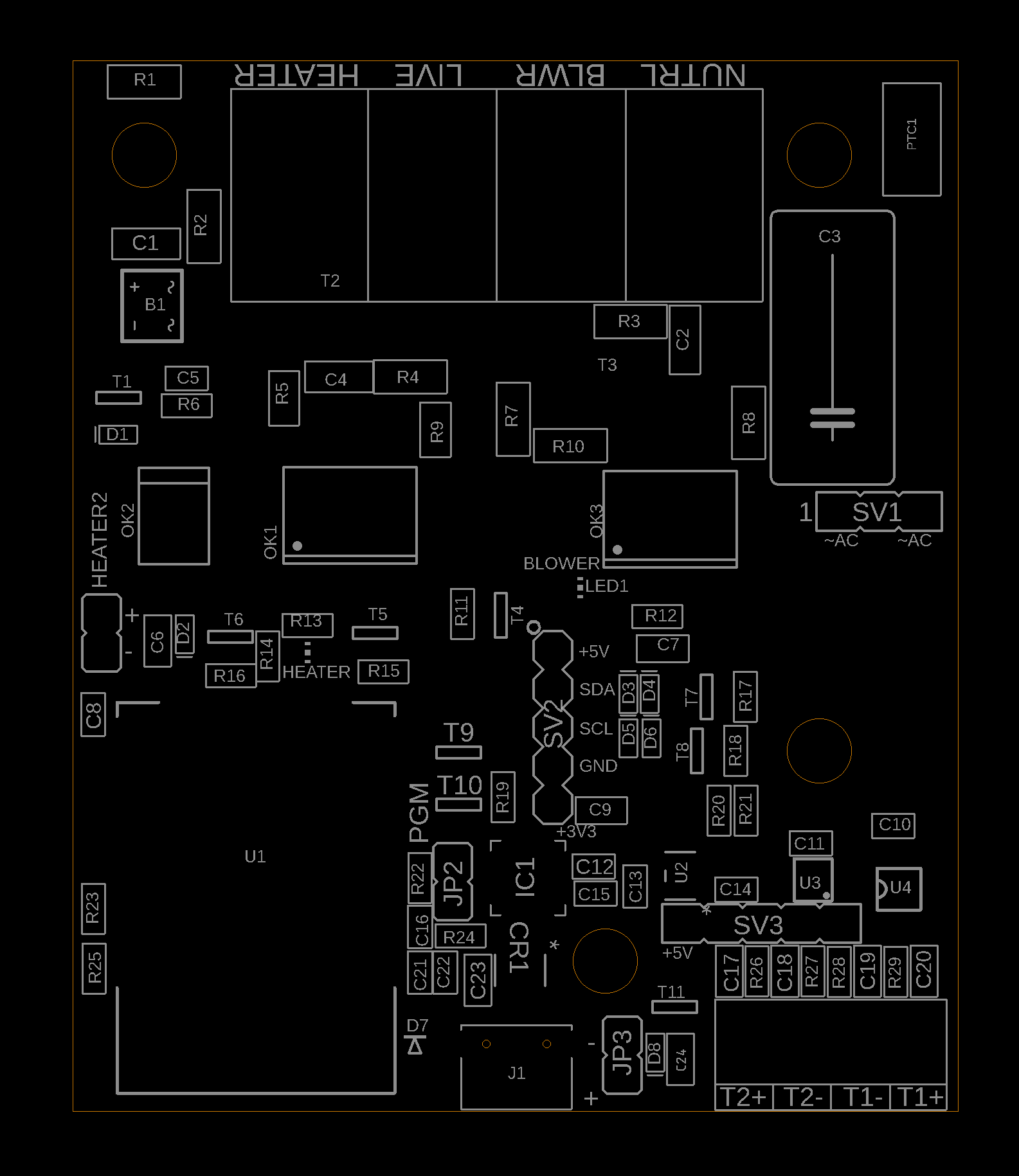
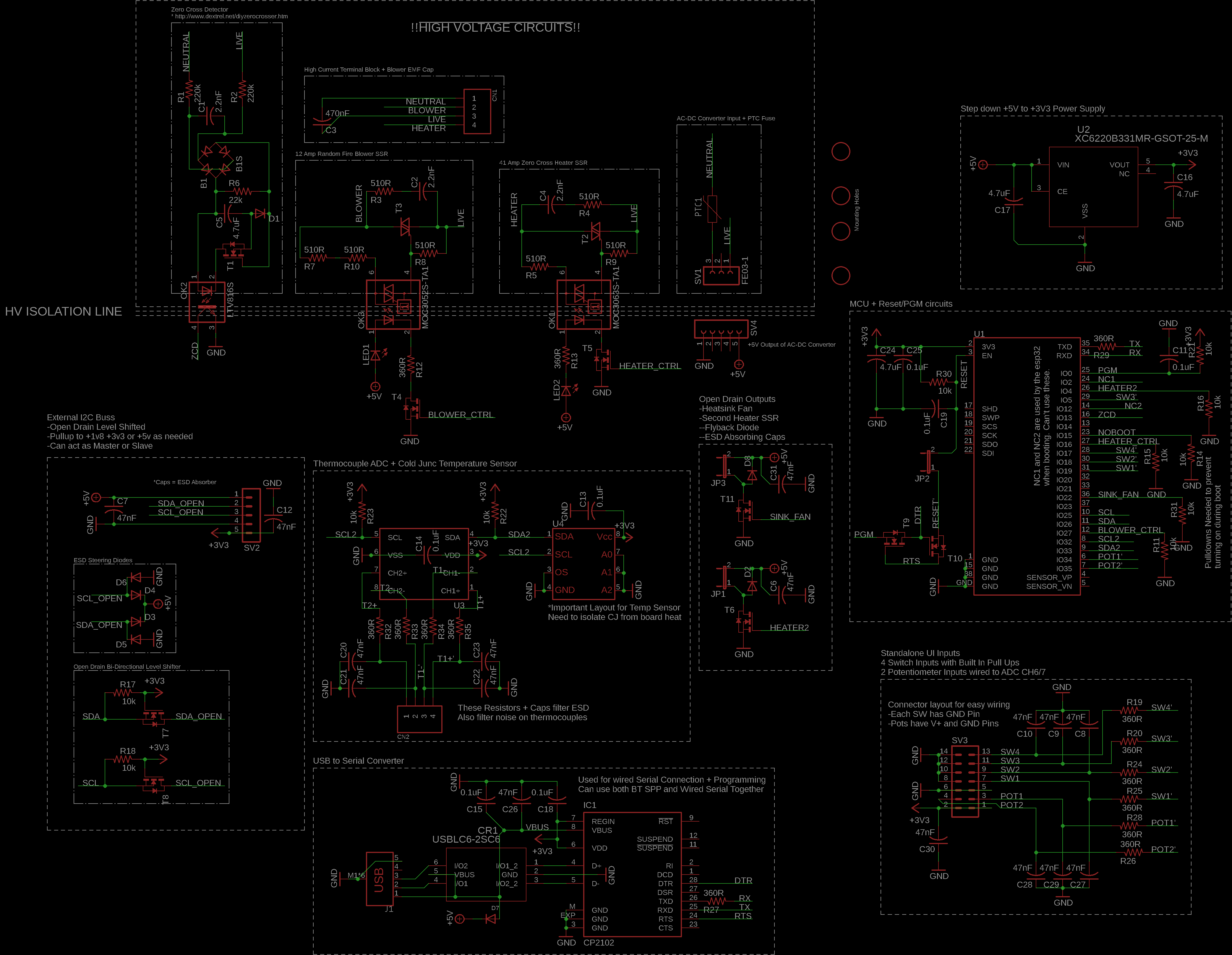
New boards came in. All previous known bugs are fixed and it's so much nicer to program now with a legit USB Bridge IC in place. No floating pins and no uncontrolled action while booting up. Got everything up and running and did a roast, a light Ethiopian dry process, and it turned out great. Ended up not saving the profile in artisan on accident! =( Anyways, one thing did happen. An esd event to the thermocouple reset the board. I realized then that I didn't have a lick of EMI/EMC filtering on those pins so I'm going to turn a PCB one more time. Before I do that however I want to see if anyone out there has any suggestions on hardware changes before I do. I'm attaching the Schematic and Layout here as images. I'm just lazy and haven't setup the git repository yet. If anyone has eagle and wants the design files send me a PM.
ahardinger attached the following images:


Edited by ahardinger on 03/13/2018 3:46 AM |
|
|
|
| ahardinger |
Posted on 03/13/2018 3:36 AM
|
|
Newbie Posts: 25 Joined: March 03, 2018 |
A lot of the circuit is actually for EMC/EMI compliance, high voltage safety, and general ruggedness. Things like using two 1210 resistors in series is because the each single resistor is only rated for ~200VDC and this board is capable of 240VAC operation. Traces are sized for 20+ Amps. Trace separation and clearances between AC Conductors is providing FUNCTIONAL INSULATION only, and even then only up to ~1500V. The separation is 1.5mm. The isolation between the HV and LV sides is much better @ 7.7mm which SHOULD provide ~5kV of safety isolation. This board hasn't been tested at any lab and I make no claims about it's safety. Approach this will caution and use your judgement to determine what's safe for you! I'm slammed with work at the moment so this project is getting very little of my time right now. But if you have any questions let me know and I'll try and answer them in a timely manner. -Aaron Edited by ahardinger on 03/13/2018 3:45 AM |
|
|
|
| greencardigan |
Posted on 03/13/2018 4:22 AM
|
 1 1/2 Pounder  Posts: 1185 Joined: November 21, 2010 |
Sounds great! So the header labelled HEATER2 is where an external SSR could be connected? What about inputs like the TC4 uses to allow it to be used standalone. The TC4 supports two potentiometers to control blower and heater levels, and up to four digital inputs. How easy is IC1 to solder? Is a QFN28 doable using hot air reflow? |
|
|
|
| ahardinger |
Posted on 03/13/2018 6:11 AM
|
|
Newbie Posts: 25 Joined: March 03, 2018 |
Quote greencardigan wrote: Sounds great! So the header labelled HEATER2 is where an external SSR could be connected? Yes, that's an open drain output with a +5v source pin so you can wire it to an external SSR without any fuss. Quote What about inputs like the TC4 uses to allow it to be used standalone. The TC4 supports two potentiometers to control blower and heater levels, and up to four digital inputs. I was thinking that it would have to be over the external i2c buss. I've got a weird tick where I need to make my layouts efficient... plus I was being lazy. Either way, here is the new layout with a 14-pin header that gives these capabilities on-board! 4 Switches supported, each input pin has a pull-up and a GND pin next to it so you can directly wire N.O. switches without any additional splices etc... 2 Potentiometers connected to ADC channels on the ESP32. Again, there are V+ and GND pins provided on the connector so you can hookup a pot without any fuss. Take a look at the copper for the pin out. All inputs are ESD/EMI/EMC protected and filtered so robust design is preserved. The board got ~7.5mm wider though... Quote How easy is IC1 to solder? Is a QFN28 doable using hot air reflow? Initially I use a hot plate from Walmart, solder paste, a stencil, and a steady hand. If I need to rework it then a hot air rework station does a fine job. When using paste make sure its high quality and fresh otherwise QFN can be problematic. Hot air, use lots of flux... You don't need paste to solder this with hot air. Just get enough solder on the pads, apply flux, and heat. Give the part a tap once the solder is molten and it should center up and clear any bridges. Its actually not hard at all given some practice. Everything else can also be hand soldered. The only "fiddly" bits are the diodes... sod523 is SMALL. Not quite as bad as hand soldering 0402 though!
ahardinger attached the following images:


Edited by ahardinger on 03/13/2018 6:35 AM |
|
|
|
| mg512 |
Posted on 03/24/2018 10:00 PM
|
 1/4 Pounder  Posts: 189 Joined: March 04, 2018 |
Oh, cool project. I just built a controller for my espresso machine based on the ESP32, and was thinking of doing a roaster controller around it as well. Guess you were faster! ;) Regarding triac on board vs separate high-voltage board: I had a similar desire to not have too many different PCBs involved with my current TC4-based board; In my case I had to have a separate 24V DC PSU anyway as I'm using a DC fan. So I put a DC regulator onto my board to convert the 24V to 5V to power the arduino, along with a transistor to drive the 24V DC fan via PWM. This way my hardware is reduced to Arduino + TC4-like shield, DC PSU, and one SSR. Of course with AC fans the situation is different. Just to check my understanding, you still need a zero-cross detection circuit to drive an AC fan with the on-board TRIAC, correct? |
|
|
|
| renatoa |
Posted on 03/25/2018 4:08 AM
|
|
Administrator Posts: 3005 Joined: September 30, 2016 |
Is this board powerful enough to be the brain of a similar controller as yours, but modular ? https://www.bangg...92733.html I.e. to run the code without major changes... Roasters: DIY: TO based IR 200-640g
Moded commercial: Skywalker, Dieckmann RoestMeister, Nesco, popper(s). Electrics: TC4ESP, MS6514, USB/Artisan/Apps, PID controllers Grinders: Arco, Xeoleo ghost burrs, Krinder, vintage PeDe Dienes, MBK Feldgrind Brew/presso: ALM pour over, Arin lever, Staresso Mirage, Hario Cafeor dripper, Flair, Kompresso, Rota Aeropress, Gaggia Mini |
|
|
|
| ahardinger |
Posted on 03/31/2018 10:01 AM
|
|
Newbie Posts: 25 Joined: March 03, 2018 |
Quote mg512 wrote: Just to check my understanding, you still need a zero-cross detection circuit to drive an AC fan with the on-board TRIAC, correct? Yes, but that's also integrated into this design. Nice on the espresso machine controller. The esp32 is pretty awesome!!! |
|
|
|
| ahardinger |
Posted on 03/31/2018 10:02 AM
|
|
Newbie Posts: 25 Joined: March 03, 2018 |
Quote renatoa wrote: Is this board powerful enough to be the brain of a similar controller as yours, but modular ? https://www.bangg...92733.html I.e. to run the code without major changes... That looks like it's based on the esp8266 chipset. They don't share the same code base but it would be easier than porting arduino code over. The low level HAL would need to be rewritten, and I'm not sure they have the same hardware peripherals. |
|
|
|

Page 2 of 2: 12
| Jump to Forum: |
Similar Threads
| Thread | Forum | Replies | Last Post |
|---|---|---|---|
| Green coffee sellers | Green Coffee | 19 | 04/10/2024 8:26 PM |
| Shipping coffee overseas. | JAVA TRADING COMPANY | 4 | 04/04/2024 1:42 AM |
| April coffee fools | Coffee Humor | 1 | 04/01/2024 2:40 PM |
| Coffee Crafters Fluid Bed Coffee Roasters | JAVA TRADING COMPANY | 4 | 03/29/2024 9:41 AM |
| Roast Color Meter - On Demand | JAVA TRADING COMPANY | 2 | 01/18/2024 1:15 PM |
Powered by PHP-Fusion Copyright © 2024 PHP-Fusion Inc
Released as free software without warranties under GNU Affero GPL v3
Designed with ♥ by NetriXHosted by skpacman