
Login

Shoutbox
You must login to post a message.
allenb
04/19/2024 8:27 AM
eximwind 
renatoa
04/18/2024 12:36 AM
bijurexim, greyberry2, N C, 
renatoa
04/17/2024 9:27 AM
 , branchu
renatoa
04/14/2024 5:56 AM
TheOtherJim and papajim,
 !
!
!allenb
04/11/2024 6:33 PM
Zemona
Forum Threads
Newest Threads
Rainfrog's Roastmast...War on Farmers by Su...
Kaleido Roaster PID ...
Green coffee sellers
Wet beans - Estimati...
Hottest Threads
| Skywalker roaster... | [292] |
| Skywalker, the AL... | [214] |
| Skywalker Roasts | [94] |
| Rainfrog's Roastm... | [54] |
| My first popcorn ... | [47] |
In Memory Of Ginny

Donations
Latest Donations
dmccallum - 10.00
JackH - 25.00
snwcmpr - 10.00
Anonymous - 2.00
Anonymous - 5.00
dmccallum - 10.00
JackH - 25.00
snwcmpr - 10.00
Anonymous - 2.00
Anonymous - 5.00
Users Online
Guests Online: 1
Members Online: 0
Total Members: 8,212
Newest Member: eximwind
Members Online: 0
Total Members: 8,212
Newest Member: eximwind
View Thread
Who is here? 1 guest(s)
 TC4+ Arduino coffee roaster shield (TC4-compatible)
|
|
| mtbizzle |
Posted on 04/30/2020 8:41 PM
|
|
1/4 Pounder  Posts: 101 Joined: April 22, 2020 |
 USB connects via the Arduino Uno -- right? So I would need a USB type B connector? Also, re. perforated sheet you used inside the enclosure for securing & grounding/earthing. Did you screw the sheet to the enclosure, and then screw all electronics to the sheet? Feel like I must be missing something. Is the TC4+/Arduino really in contact with that metal sheet? My instinct would be to use standoffs to secure things, but not sure I can use those to secure the Arduino/TC4+ because the TC4 is stacked ontop of the Arduino. Edited by mtbizzle on 04/30/2020 9:15 PM Roast: Kaldi wide, SR800 + projects
Grind: Lab sweet, Bentwood, giota w/ MP burrs, Commandante Pull: Decent, La Pavoni, Elektra Microcasa a Leva, Faemina anno 60, Kim Express |
|
|
|
| mg512 |
Posted on 04/30/2020 10:26 PM
|
 1/4 Pounder Posts: 189 Joined: March 04, 2018 |
Yes, USB type B. Most Arduinos include a suitable USB cable, usually a pretty short one though. I use the perforated sheet for earthing things. In the guide, the Arduino is indeed secured with standoffs! Not in (electrical) contact with it. I attached standoffs to the Arduino, then stacked the TC4+ on top, then secured the standoffs to the sheet. The sheet isn't strictly necessary of course, there are other ways of mounting thigns. |
|
|
|
| mtbizzle |
Posted on 05/05/2020 5:13 PM
|
|
1/4 Pounder Posts: 101 Joined: April 22, 2020 |
Apologies for the uninteresting questions here... If I am testing the power rating of the popper fan, where do I put the multimeter + & - ? Measure "V" and "A" on multimeter after fan runs for a few seconds, correct? https://imgur.com... Also I'm curious. What are people's thoughts on higher wattage roasters, like the 1200 and 1500 watt poppery's, for mods like the TC4+? Edited by mtbizzle on 05/05/2020 5:34 PM Roast: Kaldi wide, SR800 + projects
Grind: Lab sweet, Bentwood, giota w/ MP burrs, Commandante Pull: Decent, La Pavoni, Elektra Microcasa a Leva, Faemina anno 60, Kim Express |
|
|
|
| mg512 |
Posted on 05/06/2020 8:08 AM
|
|
1/4 Pounder Posts: 189 Joined: March 04, 2018 |
Voltage you would measure in parallel, current in series with the motor. You already know the (rough) voltage, as it's printed on the motor. ;) Current you don't strictly need to measure either - I never did on mine, as I didn't want to mess with measuring on something that was plugged in to mains. You could instead measure resistance of the heating coils and motor and calculate current from that. Or there might be a model number printed on the fan, and you might be able to google it. Or, you just trust that it will be of a similar magnitude as all the other popcorn machines out there, and just budget aboug 2A steady state current. If you overvolt the fan, the current will change anyway, so measuring it at stock voltage gives you a rought lower estimate at best anyway. And you need to overspec the power supply anyway, as start-up current is much higher, and not as easily measured. Bottom line, get a 5A PSU, and most likely it will be fine. Worst case, you might have to stagger the fan startup, i.e. go from 0% to 50% and then to 100%, instead of jumping directly to 100%, to lessen the startup current. The machine I used is rated at 1200W, and that has always been plenty. Bear in mind that with the dual-heating-coils-as-voltage-divider-for-DC-fan type machines, if you end up driving the primary heating coil directly from mains as in the guide, that will also significantly up the wattage it draws! Even more so on 120V than on 240V, as the 18V extra is a larger relative increase. This too is something I wouldn't worry about, unless it actually turned out to be an issue, because 99% of the time it won't. |
|
|
|
| mtbizzle |
Posted on 05/18/2020 1:10 PM
|
|
1/4 Pounder Posts: 101 Joined: April 22, 2020 |
I have the popper disassembled, intending to try to measure voltage and amperage of the fan for making a call on a fan PSU, based on what you said I guess I shouldn't do so. I know in your guide, you say, Quote I measured the resistance of the motor and both heating coils If I should do this, v.s. going with the '18v' sticker to use my 19v7.1 PSU, can someone point me to where I would put the multimeter red/blk to measure this? I also don't know how to use this ohms measurement to calculate the values I'm looking for.  Quote mg512 wrote: ... you need to overspec the power supply anyway, as start-up current is much higher, and not as easily measured. Bottom line, get a 5A PSU, and most likely it will be fine.... ... if you end up driving the primary heating coil directly from mains as in the guide, that will also significantly up the wattage it draws! ...This too is something I wouldn't worry about I have a 19v 7.1a laptop charger that I am hoping to use for this purpose, but of course only if it is appropriate. The unit just attached to the diodes in the picture above (fan & motor to my understanding) has a sticker '18v'. So 19v would be a slight overvoltage but indications seem to be that won't be a problem. What about amps? 7.1a. Just want to be sure, mains electrical and all.  Once I settle this PSU matter, will be moving forward with the build 
Edited by mtbizzle on 05/18/2020 1:31 PM Roast: Kaldi wide, SR800 + projects
Grind: Lab sweet, Bentwood, giota w/ MP burrs, Commandante Pull: Decent, La Pavoni, Elektra Microcasa a Leva, Faemina anno 60, Kim Express |
|
|
|
| mg512 |
Posted on 05/18/2020 2:43 PM
|
|
1/4 Pounder Posts: 189 Joined: March 04, 2018 |
Quote mtbizzle wrote: I have the popper disassembled, intending to try to measure voltage and amperage of the fan for making a call on a fan PSU, based on what you said I guess I shouldn't do so. I know in your guide, you say, Quote I measured the resistance of the motor and both heating coils If I should do this, v.s. going with the '18v' sticker to use my 19v7.1 PSU, can someone point me to where I would put the multimeter red/blk to measure this? I also don't know how to use this ohms measurement to calculate the values I'm looking for. Quote mg512 wrote: ... you need to overspec the power supply anyway, as start-up current is much higher, and not as easily measured. Bottom line, get a 5A PSU, and most likely it will be fine.... ... if you end up driving the primary heating coil directly from mains as in the guide, that will also significantly up the wattage it draws! ...This too is something I wouldn't worry about I have a 19v 7.1a laptop charger that I am hoping to use for this purpose, but of course only if it is appropriate. The unit just attached to the diodes in the picture above (fan & motor to my understanding) has a sticker '18v'. So 19v would be a slight overvoltage but indications seem to be that won't be a problem. What about amps? 7.1a. Just want to be sure, mains electrical and all. Once I settle this PSU matter, will be moving forward with the build I think 7A is most likely plenty. |
|
|
|
| greencardigan |
Posted on 05/19/2020 7:49 PM
|
 1 1/2 Pounder  Posts: 1185 Joined: November 21, 2010 |
Sorry I'm late to the discussion. Just wanted to add my thoughts on the remote computer options. My current controller uses a Raspberry Pi running Artisan and connected via USB to the Arduino/TC4. The Raspberry Pi sits inside my control box. I thought about adding a 8" touch screen on the front of my control box but ended up using the VNC remote access software. So using VNC I essentially have a remote screen for the raspberry pi. I usually use my phone as the screen but sometimes a tablet. |
|
|
|
| mtbizzle |
Posted on 06/06/2020 6:06 PM
|
|
1/4 Pounder Posts: 101 Joined: April 22, 2020 |
I just came across this thread over at Home Barista, discussing an issue with a PID arduino sketch that they seem to have fixed. https://www.home-...63751.html "Inconsistent power scaling"  I know in MG512's guide, he indicates either of two arduino sketches can be used. Does anyone know if either of those exhibits this issue, or if one/both don't have this problem? Roast: Kaldi wide, SR800 + projects
Grind: Lab sweet, Bentwood, giota w/ MP burrs, Commandante Pull: Decent, La Pavoni, Elektra Microcasa a Leva, Faemina anno 60, Kim Express |
|
|
|
| renatoa |
Posted on 06/07/2020 1:57 AM
|
|
Administrator Posts: 3005 Joined: September 30, 2016 |
How is this related to TC4 ? The hardware and software in his post is completely different than TC4, the only common point being Arduino, which means nothing. Arduino just execute what the program tell him to do, based on external inputs. Garbage in, garbage out. The issue I don't think it's due to PID, the power jump (in green) is too small to led to so dramatic jump in ET, could be anything else, like an airflow issue. Even the PID term is confusing for many... there isn't only one and unique PID approach. Not the last, using MAX6675 for temperature measurement is totally inappropriate for such demanding task. Edited by renatoa on 06/07/2020 2:13 AM |
|
|
|
| mg512 |
Posted on 06/08/2020 1:16 PM
|
|
1/4 Pounder Posts: 189 Joined: March 04, 2018 |
I concur, it looks like they are using a completely different sketch, and different hardware. Most likely this doesn't apply to aArtisan nor aArtisanQ_PID. |
|
|
|
| progen |
Posted on 07/12/2020 1:09 PM
|
 1/4 Pounder Posts: 82 Joined: December 17, 2019 |
Quote mtbizzle wrote: I just came across this thread over at Home Barista, discussing an issue with a PID arduino sketch that they seem to have fixed. https://www.home-...63751.html "Inconsistent power scaling" I know in MG512's guide, he indicates either of two arduino sketches can be used. Does anyone know if either of those exhibits this issue, or if one/both don't have this problem? The ET curve looks exactly like the one I get in my Frankensteined oven around each crack. Temperature is building up and just before a crack, it slows or even drops (usually around 2nd crack) and then there's a sharp rise as a good amount is released from the beans as they crack. |
|
|
|
| hstan4 |
Posted on 07/17/2020 9:33 PM
|
|
Newbie  Posts: 21 Joined: July 16, 2020 |
I?m excited to see the progress on mtbizzle?s air popper. I just recently got into home roasting and too have a Nostalgia air popper. I?m highly considering getting the TC4+ and hoping I can figure the wiring and other parts out without too much trouble. I love the in depth responses here and am looking forward to participating on the forum. One thing I?m struggling with is determining which options to add to the TC4+. I?m confident I can learn the through hole soldering without too much trouble but don?t know how difficult configuring the status lights etc would be into this setup (or if it?s not too difficult) if I don?t get the preconfigured options. I?d love to have it configured to ensure there?s little room for error, but also am really curious to truly understand how it all works, so want a good mix of both to ensure I can get it working. Either way I?m glad I found this forum and have loved what I?ve learned so far. Thank you all for the contributions and awesome TC4 shields |
|
|
|
| mg512 |
Posted on 07/18/2020 10:21 PM
|
|
1/4 Pounder Posts: 189 Joined: March 04, 2018 |
Quote hstan4 wrote: I?m excited to see the progress on mtbizzle?s air popper. I just recently got into home roasting and too have a Nostalgia air popper. I?m highly considering getting the TC4+ and hoping I can figure the wiring and other parts out without too much trouble. I love the in depth responses here and am looking forward to participating on the forum. One thing I?m struggling with is determining which options to add to the TC4+. I?m confident I can learn the through hole soldering without too much trouble but don?t know how difficult configuring the status lights etc would be into this setup (or if it?s not too difficult) if I don?t get the preconfigured options. I?d love to have it configured to ensure there?s little room for error, but also am really curious to truly understand how it all works, so want a good mix of both to ensure I can get it working. Either way I?m glad I found this forum and have loved what I?ve learned so far. Thank you all for the contributions and awesome TC4 shields Setting up the Bluetooth module is a pain, and not really in a way that will teach you anything useful. Personally if I were to choose, that's the first thing I'd want to not have to deal with. Flashing the Arduino, on the other hand, is also a pain the first time you do it, but at least it's a useful skill to have, in case you ever want to change the configuration or for other future projects. For through-hole soldering, I'd advise learning on something cheap first, if you've never done it before. |
|
|
|
| hstan4 |
Posted on 07/19/2020 8:03 AM
|
|
Newbie Posts: 21 Joined: July 16, 2020 |
I purchased the TC4+ right before you had responded so I?ll have to make do with what I?ve got and think it will work out ok. I just did the kit with an Arduino included so I?ll in the meantime I?ll acquire the other parts and get a soldering kit and give that a go on something. Thanks for the quick response and am looking forward to getting the TC4+! |
|
|
|
| hstan4 |
Posted on 07/20/2020 12:41 AM
|
|
Newbie Posts: 21 Joined: July 16, 2020 |
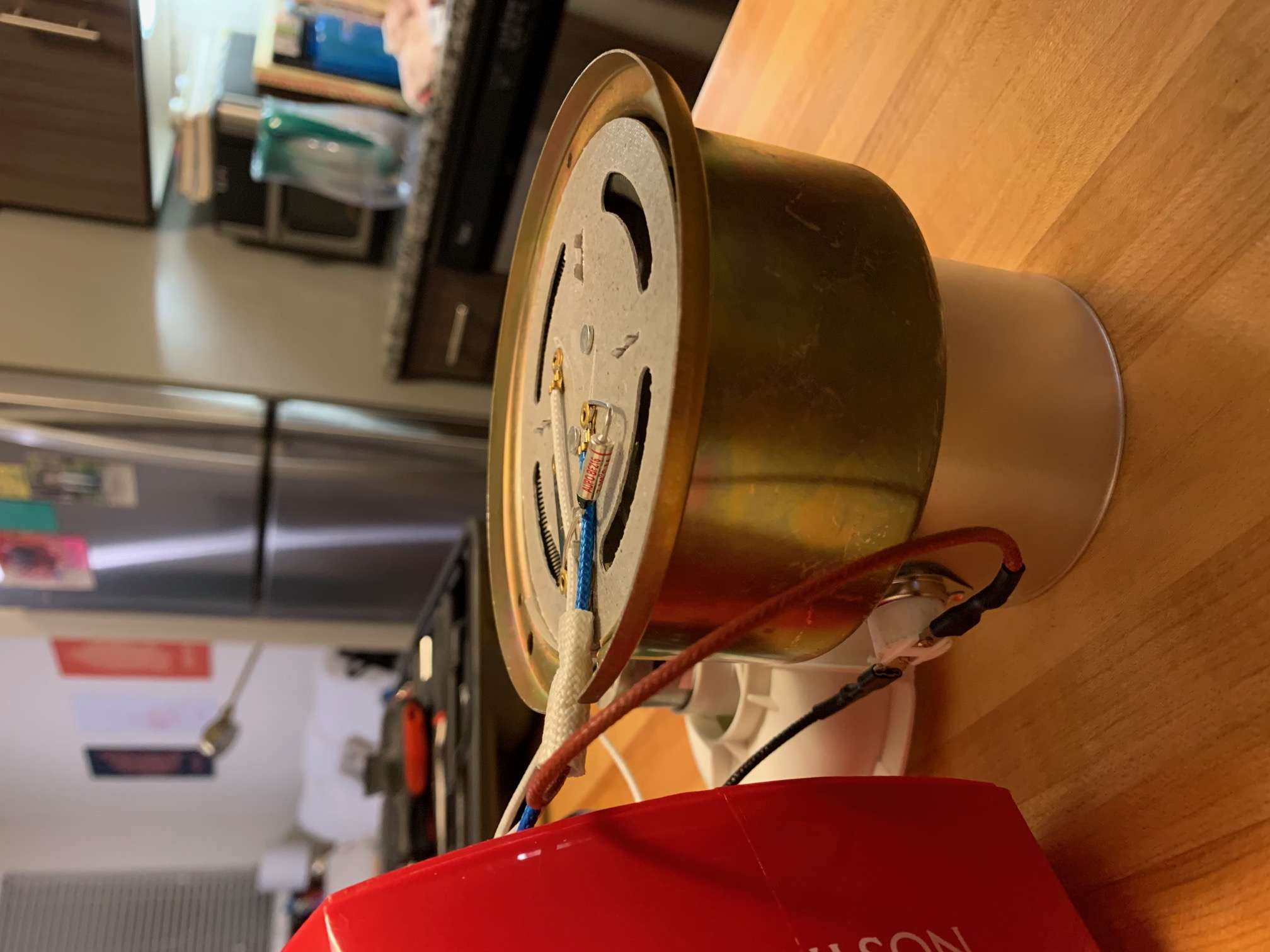
I thought I'd upload some images of my Nostalgia air popper to give anyone curious of what the wiring looks like and to hopefully get some confirmation from people who know far more than I do. I'm following along on an instructables article and it seems this popper is a bit different than the one he has (with the main difference being no PCB on mine). Just a disclaimer: I have very little experience with this so if my assumptions are wrong please let me know. 1) The rectifier (black cylindrical diodes attached to the fan motor?) is wired differently from the instructables example in that they aren't soldered onto a PCB. How would this be modified instead, as well as replacing it with a flyback diode? I'm guessing you'd heat the solder connecting the diodes, but then I'm unsure on how you'd wire it back correctly. 2) There must be a hidden second heating coil and then also the main one that has three wires coming into it: 1) the reddish brown wire from the metal chamber 2) the blue wire that's also connected to the power wire and 3) the white wire connected to the fan. I'm sure there's many other thoughts I'm not considering, but hopefully someone can break this popper's wiring down. I see a few similarities but also notable differences to ones with a PCB. Not sure if the image upload is working properly so I've added the imgur links. Please let me know if I can provide anything else, I've tried to provide images of everything clearly. https://imgur.com/a/g8sVqtx
hstan4 attached the following images:


|
|
|
|
| renatoa |
Posted on 07/20/2020 2:18 AM
|
|
Administrator Posts: 3005 Joined: September 30, 2016 |
I am modifying right now a popper looking very close to yours, the main difference is the thermostat location, it is mounted on heater plate, instead the metal bar, not wired as yours. The motor diodes are soldered as yours, I left them in place, not removed. The white wires from the rectifier should be cut and routed to the 24V DC power source, in series with the PWM voltage/speed variator. The blue+red brownish wires are the main heater leads, you can use thermostat connectors to insert the SSR instead. Everything else can be left as is. I can draw on your pictures if it helps. |
|
|
|
| mg512 |
Posted on 07/20/2020 8:54 AM
|
|
1/4 Pounder Posts: 189 Joined: March 04, 2018 |
Oh, interesting, is that red/brown wire connected to a thermostat on the roast chamber? Haven't seen that before. As far as I can tell from the pictures, renatoa has it right: For the fan, you can either desolder the rectifier diodes, and solder wires and a flyback diode directly onto the motor terminals. Or, in principle, you should be able to keep the rectifier diodes as they are, and they should act as a flyback as well. I've never done this in practice myself, but in principle it should work. For the heater, there is most likely indeed a seconday heating coil nearer the center of the assembly. You should be able to see it if you hold the assembly sideways at the right angle. And it looks like the wiring of the heating coils is indeed a bit different than what I've seen before. If I am piecing this together correctly from the photos (but double check all of this!) it looks like the main heating coil is connected to blue and brown, which are neutral and live AC. AC Neutral is then also connected to one side of the secondary heating coil through that metal bar / tab on the heater assembly. The other side of the secondary coil connects to the white wire which goes to the fan, the other side of which is connected to AC Live. So fan + secondary are in series, and connected directly to AC. (Most machines I've seen before had fan and secondary in parallel, and connected to neutral and one end of the primary coil.) Assuming this is all correct, you would indeed use the blue and brown wires from the heater assembly. I might be wrong about this of course, hard to tell for sure from pictures. Double check all of this, and if you're not experienced with working with AC ask an electrician for help! |
|
|
|
| renatoa |
Posted on 07/20/2020 11:05 AM
|
|
Administrator Posts: 3005 Joined: September 30, 2016 |
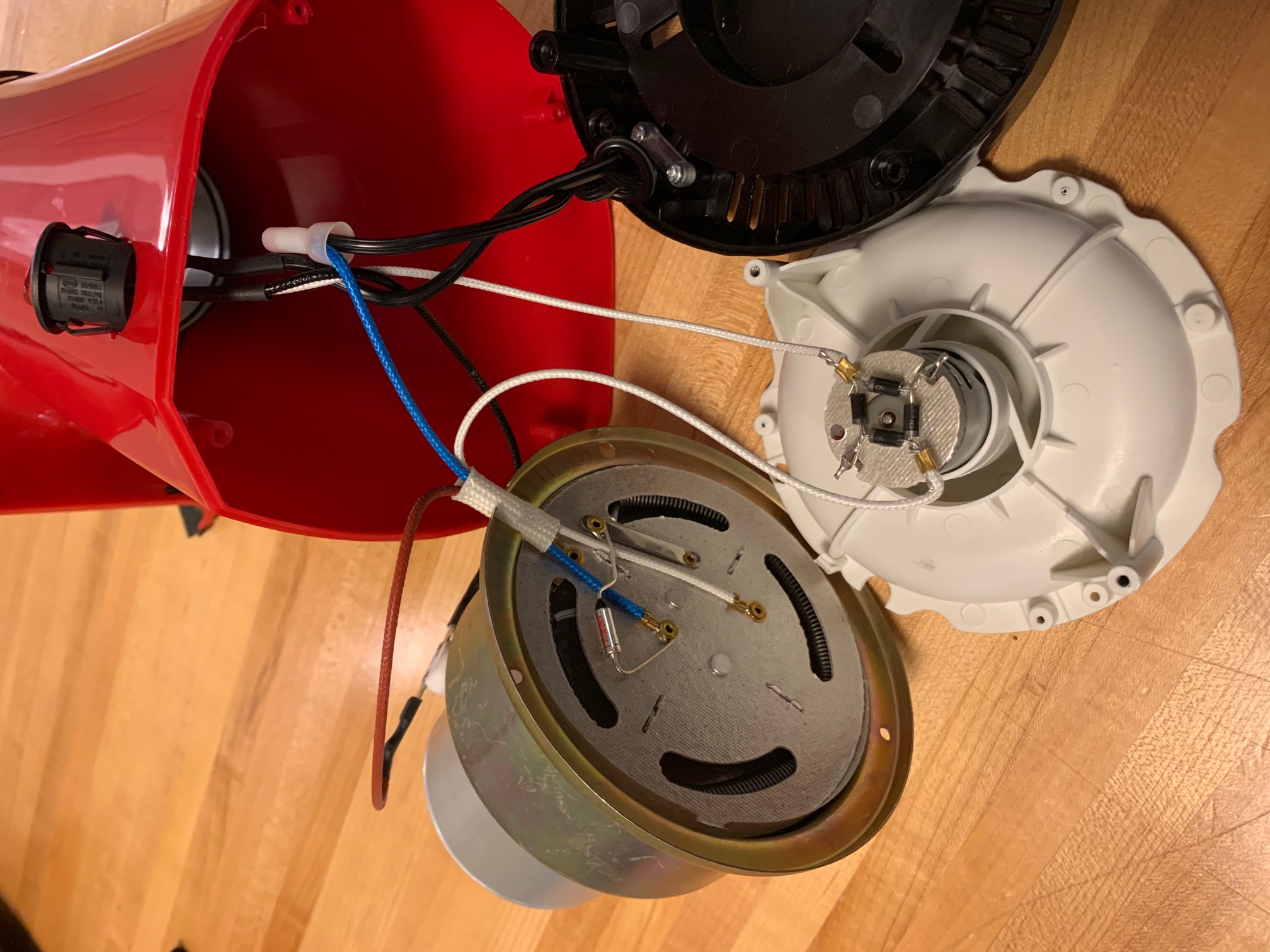
Attached you can see the heater plate of the popper I am actually modding... just for the record. The bimetal on the right has the same function and connection as the thermostat in hstan4 model. The fiberglass cloth white tube on the left is an insulation for the thermal fuse we can see naked in the pictures above. By far I prefer hstan4 model, there is non need to dismount heater plate in order to bypass the bimetal, and the thermostat leads can be used for SSR connections with less much tinkering. ...
renatoa attached the following image:

|
|
|
|
| CK |
Posted on 07/20/2020 11:36 AM
|
|
1/2 Pounder  Posts: 250 Joined: December 07, 2018 |
Quote renatoa wrote: Attached you can see the heater plate of the popper I am actually modding... just for the record. The bimetal on the right has the same function and connection as the thermostat in hstan4 model. The fiberglass cloth white tube on the left is an insulation for the thermal fuse we can see naked in the pictures above. By far I prefer hstan4 model, there is non need to dismount heater plate in order to bypass the bimetal, and the thermostat leads can be used for SSR connections with less much tinkering. ... As far as I've experienced, you should be able to simply use tweezers to pull out the piece of deformable metal from under the copper main connection of the bimetal thermal safety, without disassembling the whole heater plate to bypass... Gently lift the copper main connection slightly while pulling sideways on the deformable metal plate. With that piece out, the main connection springs back down making a good connection without the safety. |
|
|
|
| mg512 |
Posted on 07/20/2020 12:04 PM
|
|
1/4 Pounder Posts: 189 Joined: March 04, 2018 |
I'll add that in the Severin machine I used, I didn't have to bypass the bimetal thermostat at all. Unless you find that it triggers at too low a temperature, I would just leave it as it is. |
|
|
|
| renatoa |
Posted on 07/20/2020 12:08 PM
|
|
Administrator Posts: 3005 Joined: September 30, 2016 |
Mine triggers at 185 C, too low to reach first crack. |
|
|
|
| hstan4 |
Posted on 07/20/2020 1:52 PM
|
|
Newbie Posts: 21 Joined: July 16, 2020 |
Quote mg512 wrote: Oh, interesting, is that red/brown wire connected to a thermostat on the roast chamber? Haven't seen that before. As far as I can tell from the pictures, renatoa has it right: For the fan, you can either desolder the rectifier diodes, and solder wires and a flyback diode directly onto the motor terminals. Or, in principle, you should be able to keep the rectifier diodes as they are, and they should act as a flyback as well. I've never done this in practice myself, but in principle it should work. For the heater, there is most likely indeed a seconday heating coil nearer the center of the assembly. You should be able to see it if you hold the assembly sideways at the right angle. And it looks like the wiring of the heating coils is indeed a bit different than what I've seen before. If I am piecing this together correctly from the photos (but double check all of this!) it looks like the main heating coil is connected to blue and brown, which are neutral and live AC. AC Neutral is then also connected to one side of the secondary heating coil through that metal bar / tab on the heater assembly. The other side of the secondary coil connects to the white wire which goes to the fan, the other side of which is connected to AC Live. So fan + secondary are in series, and connected directly to AC. (Most machines I've seen before had fan and secondary in parallel, and connected to neutral and one end of the primary coil.) Assuming this is all correct, you would indeed use the blue and brown wires from the heater assembly. I might be wrong about this of course, hard to tell for sure from pictures. Double check all of this, and if you're not experienced with working with AC ask an electrician for help! After further examining, you seem to be spot on with your assessment. The following is how I see that it works: - The fan motor (through the white wire) and primary heating coil (red/brown wire through the thermostat on the roast chamber) are connected to AC live in parallel when the switch is on - The white wire is connected from the switch to one side of the rectifier on the fan motor, converting AC to DC power - From the other side of the rectifier, the white wire connects to the secondary heating coil of the heating element. This inner, secondary coil wraps around to the bottom of the metallic strip on the node closest to where the white wire first connected to the secondary coil. - Meanwhile, the black wire coming from the switch when on, is connected to the thermostat and the brown/red wire. This brown/red wire is connected to the main coil of the heating element, and wraps around to the bottom of the metallic strip, but on the other node where the thermal fuse is also connected. - Now, the resulting current coming from the metallic strip is connected to the thermal fuse, which then passes back onto the blue wire, AC Neutral. - Finally, AC Neutral is connected back to the power source to complete the circuit. Does that seem like the correct flow from what you can tell? I'm obviously new to this, but would love to have this confirmed for me and future people in my place to understand how the current flows. If anything is incorrect, please let me know. I hope there's some agreement on the best way to wire this to the TC4+ board etc. as I'm not sure of the consensus on keeping vs. removing the rectifier / if I should place a flyback diode on if removing. A few people have pointed out that the risks of measuring voltage live could be, so I'm instead leaning towards measuring the resistance of the motor and both heating coils while the machine is off, as the Instructables article mentions (I haven't measured this before, but think I could figure it out with a multimeter). However, other than looking up the supposed model of the fan motor, the author doesn't mention a current value that he measured, so not sure how he arrived at 18V without having current as well as resistance. In terms of acquiring parts, I'm still searching for the correct DC PSU, trying to ensure I get one with matching voltage (as I just mentioned, I haven't measured to confirm yet, but others have said it's likely 18V) and finding one with amperage of 2-3 times the amount (which I've also seen users say one that's 7A would likely be fine, but don't think any specifics have been confirmed). Additionally, it seems basic ring and spade connectors should do the trick, and thermocouples and the SSR I seem to be pretty set on. I'm sure the wiring to the TC4+ will bring plenty of other questions I'm unsure of, but I'm hoping the methods are fairly similar once this popper's wiring is taken care of. I know this was long, but I'm hoping that this will help others in the future think through the same things I've come across. Again, I haven't even used Ohm's Law or anything along these lines since I took science in high school, so I obviously have no clue what I'm talking about besides what I've learned tinkering, but hope what I've written makes sense, and if it doesn't please correct me.  |
|
|
|
| harryf |
Posted on 07/27/2020 9:50 AM
|
|
Newbie Posts: 27 Joined: July 13, 2020 |
I have just finished connecting up my popper roaster setup as in the instructables article, and have a problem with thermocouple readings. if I leave the fan psu off, and click "ON" on Artisan, the readings are correct, but as soon as I switch on the psu the readings are garbage. This is with fan and heater off. I disconnected the psu and connected my bench psu and everything worked great, even with fan and heater on.I am using the same type of psu module as in the article. This is driving me nuts. Any ideas? ps i checked the ripple on both PSUs with my multimeter and they seemed about the same, but with no oscilloscope I can't be sure. |
|
|
|
| mg512 |
Posted on 07/27/2020 2:41 PM
|
|
1/4 Pounder Posts: 189 Joined: March 04, 2018 |
Quote harryf wrote: I have just finished connecting up my popper roaster setup as in the instructables article, and have a problem with thermocouple readings. if I leave the fan psu off, and click "ON" on Artisan, the readings are correct, but as soon as I switch on the psu the readings are garbage. This is with fan and heater off. I disconnected the psu and connected my bench psu and everything worked great, even with fan and heater on.I am using the same type of psu module as in the article. This is driving me nuts. Any ideas? ps i checked the ripple on both PSUs with my multimeter and they seemed about the same, but with no oscilloscope I can't be sure. Hm, odd. Are the Arduino and TC4+ still responsive with the fan PSU connected? I.e. you can still e.g. turn on/off fan and heater? It's only the thermocouple readings that are affected? And when you say it's working with your bench power supply, you mean you connect the bench PSU in place of the other PSU, i.e. connect it to the DC IN header? |
|
|
|
| renatoa |
Posted on 07/27/2020 3:01 PM
|
|
Administrator Posts: 3005 Joined: September 30, 2016 |
May I ask if all the unused inputs are shorted ? |
|
|
|

| Jump to Forum: |
Similar Threads
| Thread | Forum | Replies | Last Post |
|---|---|---|---|
| Kaleido Roaster PID parameters | Roasting Coffee | 2 | 04/13/2024 3:07 PM |
| Green coffee sellers | Green Coffee | 19 | 04/10/2024 8:26 PM |
| Skywalker roaster mods | Other Roasters | 293 | 04/07/2024 4:31 PM |
| Shipping coffee overseas. | JAVA TRADING COMPANY | 4 | 04/04/2024 1:42 AM |
| Skywalker, the ALM chinese one pound roaster | Other Roasters | 215 | 04/02/2024 1:48 AM |
Powered by PHP-Fusion Copyright © 2024 PHP-Fusion Inc
Released as free software without warranties under GNU Affero GPL v3
Designed with ♥ by NetriXHosted by skpacman