
Login

Shoutbox
You must login to post a message.
renatoa
04/17/2024 9:27 AM
 , branchu
renatoa
04/14/2024 5:56 AM
TheOtherJim and papajim,
 !
!
!allenb
04/11/2024 6:33 PM
Zemona

renatoa
04/11/2024 9:19 AM
Mrbones and sgupta,  ?
?
?renatoa
04/10/2024 1:09 AM
 , Ed K
Forum Threads
Newest Threads
War on Farmers by Su...Kaleido Roaster PID ...
Green coffee sellers
Wet beans - Estimati...
Skywalker roaster mods
Hottest Threads
| Skywalker roaster... | [292] |
| Skywalker, the AL... | [214] |
| Skywalker Roasts | [94] |
| My first popcorn ... | [47] |
| War on Farmers by... | [39] |
In Memory Of Ginny

Donations
Latest Donations
dmccallum - 10.00
JackH - 25.00
snwcmpr - 10.00
Anonymous - 2.00
Anonymous - 5.00
dmccallum - 10.00
JackH - 25.00
snwcmpr - 10.00
Anonymous - 2.00
Anonymous - 5.00
Users Online
Guests Online: 1
Members Online: 0
Total Members: 8,208
Newest Member: branchu
Members Online: 0
Total Members: 8,208
Newest Member: branchu
View Thread
Who is here? 1 guest(s)
Page 1 of 2: 12
|
 DIY SSR with '555
|
|
| bvwelch |
Posted on 12/28/2007 2:18 PM
|
 1 1/2 Pounder  Posts: 1064 Joined: December 27, 2007 |
Greetings, NOTE-- this project is roughly equivalent to a "router speed controller" which you can find at Harbor Freight and elsewhere for about $10. Check out the other discussions here about the "router speed controller". What I am doing with this particular triac driver, is not "random phase" signaling, but rather, I am literally simulating the on/off toggling of the power, like some of you all do with the switch on your poppers-- On for a while, off for a while. The "trick" is that this MOC3041 has a built-in "zero voltage crossing" circuit, which means that it will "turn on" the triac at the moment the input A.C. crosses the zero volts point. This reduces noise spikes in your A.C. lines. A really cheap way to drive a triac, without any software involved, would be some sort of '555 timer chip circuit. The potentiometer would just vary the '555 duty cycle. What is needed, is simply a repeative signal with the desired duty cycle. The MOC3041 triac driver will do the rest, since it has built-in zero voltage crossing. I confess that I haven't built the '555 circuit, since I chose to use a little microcontroller chip instead. But it should be easy enough to do. I'll try and build up a circuit sometime. Or maybe one of you would like to give it a try yourself and report your findings. Bill Edited by bvwelch on 01/18/2008 5:47 AM |
|
|
|
| seedlings |
Posted on 12/29/2007 5:05 PM
|
 1 1/2 Pounder Posts: 4226 Joined: June 27, 2007 |
Oh, this is very good stuff. My son got a sweet radio shack electronics kit for Christmas... I'll have to start playing! I took the liberty of posting your circuits here since you gave free access... I hope I didn't overstep! Referring to your diagrams online, I'm not sure of the relationship between the first two. Could you explain? I see the pot on the 555 circuit, and I assume that's the output voltage adjustment trim. Then it says "to triac driver." How does the 555 circuit connect to the triac circuit? Does pin 3 on the 555 go thru the 220K to pin 1 of the MOC3041? And finally, I see the temperature controller with the thermocouple. Right now I'm only interested in cycling the AC power to "adjust the temperature." 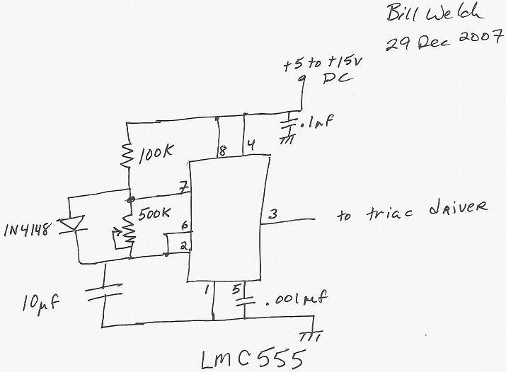 ------------------------------------------------------------------------------------------- 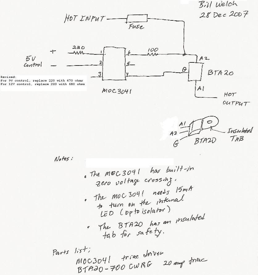 ------------------------------------------------------------------------------------------- 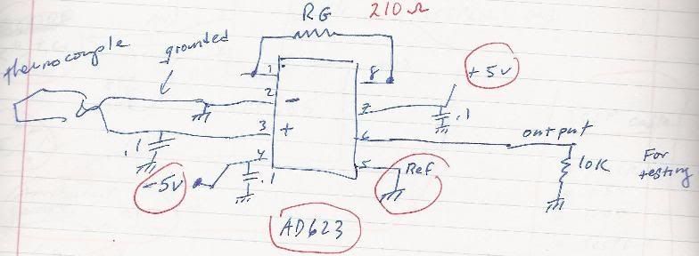 CHAD Edited by seedlings on 12/29/2007 5:58 PM Roaster: CoffeeAir II 2# DIY air roaster
Grinder: Vintage Grindmaster 500 Brewers: Vintage Cory DCU DCL, Aeropress, Press, Osaka Titanium pourover |
|
|
|
| seedlings |
Posted on 12/30/2007 3:48 PM
|
|
1 1/2 Pounder Posts: 4226 Joined: June 27, 2007 |
Genius! Will a 9V battery power this circuit OK? CHAD Roaster: CoffeeAir II 2# DIY air roaster
Grinder: Vintage Grindmaster 500 Brewers: Vintage Cory DCU DCL, Aeropress, Press, Osaka Titanium pourover |
|
|
|
| bvwelch |
Posted on 12/30/2007 4:53 PM
|
|
1 1/2 Pounder Posts: 1064 Joined: December 27, 2007 |
Sure, you can run it off 9 volts. Just change the resistor on the input to the triac driver. I believe I updated the schematic already with that value. If I remember correctly, change the 220 ohm to 470. Long term, you may want a wal-wart, but a 9V "transistor battery" should last a long time. Taking a wild guess here -- 10 or 20 hours. Be sure to switch it off when not in use. Bill |
|
|
|
| seedlings |
Posted on 01/02/2008 2:39 PM
|
|
1 1/2 Pounder Posts: 4226 Joined: June 27, 2007 |
I took my son's electronic set to work and instead of lunch, I made up your 555 circuit. It worked great blinking the LED at various on-off cycles. I couldn't make up the rest of the triac. There's a couple of dozen chips in here, but the 555 was the only piece of your circuit. I may stop by ratshack to see if they have the others. Thanks, Bill. I can't wait to get this up! CHAD
seedlings attached the following image:
![Image003[637].jpg](../forum/attachments/Image003[637].jpg)
Roaster: CoffeeAir II 2# DIY air roaster
Grinder: Vintage Grindmaster 500 Brewers: Vintage Cory DCU DCL, Aeropress, Press, Osaka Titanium pourover |
|
|
|
| seedlings |
Posted on 01/09/2008 8:21 PM
|
|
1 1/2 Pounder Posts: 4226 Joined: June 27, 2007 |
OK, thanks Bill for the ICs! Just bench tested the entire circuit (connected to a 40W lightbulb) and it worked GREAT! Except... could you clarify the wattage for the 100 ohm resistor between the MOC3041 and the triac, because I had to pull the plug due to the all too familiar burned electronics smell. I'm sure that 100 ohm was the culprit (I only used a 1/4 watt that I had on hand). Do you know if a 1 watt would be safer? Thanks, CHAD Edited by seedlings on 01/09/2008 8:21 PM Roaster: CoffeeAir II 2# DIY air roaster
Grinder: Vintage Grindmaster 500 Brewers: Vintage Cory DCU DCL, Aeropress, Press, Osaka Titanium pourover |
|
|
|
| seedlings |
Posted on 01/10/2008 8:44 AM
|
|
1 1/2 Pounder Posts: 4226 Joined: June 27, 2007 |
My 11 year old son helped me wire this in on his electronics set breadboard. It could've just been the weak busses on his breadboard. I took it apart, and plan to re-wire and solder it onto the circuit board you sent. I'll probably get a 1 watt just to be safe. The 1/4 watt looked a little tinge of brown, but still measured 100.2 ohms. I'll send pictures of the new circuit. Thanks again, Bill! CHAD Roaster: CoffeeAir II 2# DIY air roaster
Grinder: Vintage Grindmaster 500 Brewers: Vintage Cory DCU DCL, Aeropress, Press, Osaka Titanium pourover |
|
|
|
| seedlings |
Posted on 01/10/2008 3:00 PM
|
|
1 1/2 Pounder Posts: 4226 Joined: June 27, 2007 |
I had played with it for about 2 or 3 minutes varying from full on to very slow blinking, and I believe it was blinking about once per second when I pulled the plug. I'm sure the Triac was wired correctly. I triple checked everything before I put the AC to it, based on past experience. CHAD Roaster: CoffeeAir II 2# DIY air roaster
Grinder: Vintage Grindmaster 500 Brewers: Vintage Cory DCU DCL, Aeropress, Press, Osaka Titanium pourover |
|
|
|
| bvwelch |
Posted on 01/10/2008 5:28 PM
|
|
1 1/2 Pounder Posts: 1064 Joined: December 27, 2007 |
Chad, OK, I think you're on to something here. I just re-read the information on this page. http://www.simple...sistor.asp I'm am still mulling it over, but what I *think* it is saying, is that for a small load, like your 40W bulb, you need a smaller resistor. Seems counterintuitive, but that is what is says. So, you might lower the resistor, or get a higher wattage bulb, or a hot plate, or a popper, etc. Also, is it possible that you had the HOT and NEUTRAL wires reversed? It looks like the culprit is your lightbulb-- probably has a large inrush current, plus the load being so small, compared to what the triac was meant for (its a 20 amp triac), is causing the resistor to get hot. You can try a bigger wattage, or a smaller value-- 22 ohms was suggested. Perhaps best would be a real heater winding instead of a light bulb. When I did my tests, I was using one of those mini floresent bulbs that screws into a standard lamp socket. Bill Thanks, Bill Edited by bvwelch on 01/18/2008 5:37 AM |
|
|
|
| seedlings |
Posted on 01/10/2008 6:10 PM
|
|
1 1/2 Pounder Posts: 4226 Joined: June 27, 2007 |
Not possible that the HOT and NEUTRAL were reversed. Part of that triple check! CHAD Roaster: CoffeeAir II 2# DIY air roaster
Grinder: Vintage Grindmaster 500 Brewers: Vintage Cory DCU DCL, Aeropress, Press, Osaka Titanium pourover |
|
|
|
| seedlings |
Posted on 01/11/2008 9:03 PM
|
|
1 1/2 Pounder Posts: 4226 Joined: June 27, 2007 |
Well, that would explain it. Plan on hooking it up to a popper's heat element in the near future. I'll get pics and results up soon. First thing this weekend I need to get all the downed limbs out of my yard leftover from the ice storm. Weather and illness have been dreaded foes lately, interrupting playtime. CHAD Roaster: CoffeeAir II 2# DIY air roaster
Grinder: Vintage Grindmaster 500 Brewers: Vintage Cory DCU DCL, Aeropress, Press, Osaka Titanium pourover |
|
|
|
| seedlings |
Posted on 01/16/2008 10:45 PM
|
|
1 1/2 Pounder Posts: 4226 Joined: June 27, 2007 |
Still need to get power switches and a fuse, but here it is. Thanks for all you help so far, Bill! The (giant) heatsink is off an old cpu. I drilled a hole for the screw and put on some thermal grease.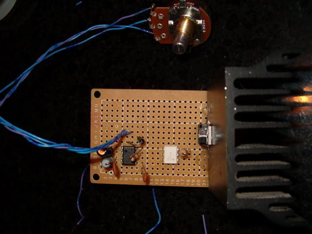 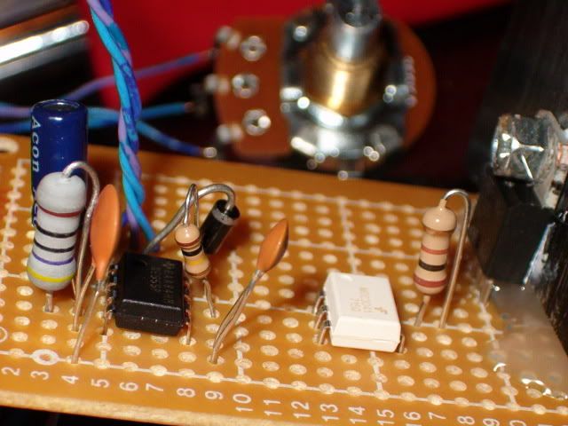 My latest question is regarding the 9V power supply. The wall wart I want to use puts out 11.2V DC. Do you think that'll be OK? Should I change the 470 ohm resistor out? CHAD Roaster: CoffeeAir II 2# DIY air roaster
Grinder: Vintage Grindmaster 500 Brewers: Vintage Cory DCU DCL, Aeropress, Press, Osaka Titanium pourover |
|
|
|
| seedlings |
Posted on 01/17/2008 8:33 AM
|
|
1 1/2 Pounder Posts: 4226 Joined: June 27, 2007 |
Yes, it's hot glue. I used it for stability because of that overkill heatsink. I figured there'd be some vibrations once it's connected to a roaster. Not sure the melting point, but it's higher than the melting point of skin. CHAD Roaster: CoffeeAir II 2# DIY air roaster
Grinder: Vintage Grindmaster 500 Brewers: Vintage Cory DCU DCL, Aeropress, Press, Osaka Titanium pourover |
|
|
|
| seedlings |
Posted on 01/18/2008 11:07 PM
|
|
1 1/2 Pounder Posts: 4226 Joined: June 27, 2007 |
And... here's how I burn one up.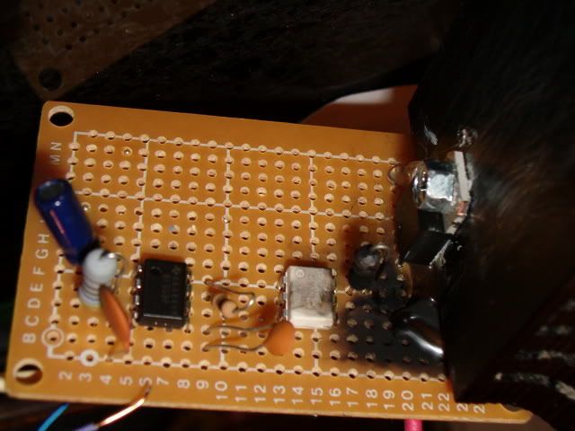 That crispy black piece of charcoal (on the right) used to be a 100 ohm resistor. Do you think I wired something wrong?!?!?!? I'm tired. Going to bed. CHAD Roaster: CoffeeAir II 2# DIY air roaster
Grinder: Vintage Grindmaster 500 Brewers: Vintage Cory DCU DCL, Aeropress, Press, Osaka Titanium pourover |
|
|
|
| bvwelch |
Posted on 01/19/2008 6:45 AM
|
|
1 1/2 Pounder Posts: 1064 Joined: December 27, 2007 |
Wow, I am sorry that happened, and I am glad you're OK! I suspect, looking at my hand-drawn schematic above, that I didn't make the pin-out of the triac crystal clear. The "Gate" pin is not the middle pin. It is at the bottom right in your photos. The middle pin is A2, which should be the input HOT terminal, and the top right pin is your output to the popper heater. My drawing of the triac schematic is just a block, where I tried to show the "function" of the block -- a switch, or sort of like a relay. With the "gate" (control) coming in from the left (center), and the input coming from the top, and the output going down from the bottom. But that isn't the physical pinout. I did include a sketch of the chip just below the block. But obviously I didn't make it as clear as possible. I do recommend changing the capacitor on the '555 from 10uF to 1uF, for a better on/off cycle time. But that wouldn't cause the sort of failure you're seeing. Please send a photo of your wiring underneath. Referring again to your photo above, the output of the 100 ohm resistor should be going to the bottom pin of the triac. The input HOT AC should be going to the middle pin, and the output from the triac, to the popper, should be the top pin. At this point, both the MOC3041 and the BTA20 may be destroyed.  I've built and tested this circuit, twice, and it works for me. I've run the version with my cpu instead of the '555 for many, many hours. I've also run the '555 version for a few minutes, and it worked with the popper fine. I will do more testing, and send a photo later today.  Here is the back-side of my '555 board. And that heatsink may be too small, it is experimental. But look at the triac pins. Remember, this is the underneath side of the chip. The "gate" pin is on the left. The HOT AC input is in the middle, and the HOT AC output is on the right. Bill Edited by bvwelch on 01/19/2008 9:35 AM |
|
|
|
| seedlings |
Posted on 01/19/2008 7:59 PM
|
|
1 1/2 Pounder Posts: 4226 Joined: June 27, 2007 |
IT WORKS!!!! I went ahead and rebuilt the entire circuit, and it worked on the first try! In this video, I've already been playing with it for a few minutes and tripped the main heater thermostat, but the secondary coil is still pumping! 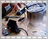 Here's the front of the board: 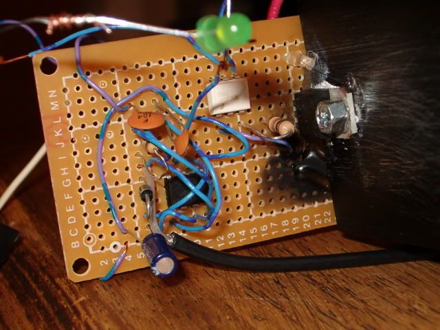 And here's the back side (notice all my previous burns and un-solders!): 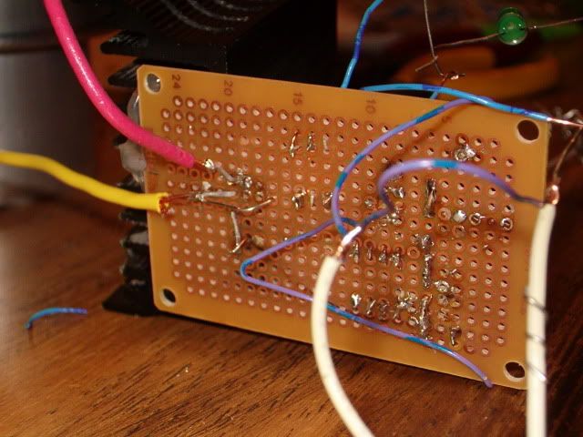 Thanks again, Bill! CHAD Edited by seedlings on 01/19/2008 8:08 PM Roaster: CoffeeAir II 2# DIY air roaster
Grinder: Vintage Grindmaster 500 Brewers: Vintage Cory DCU DCL, Aeropress, Press, Osaka Titanium pourover |
|
|
|
| bvwelch |
Posted on 01/19/2008 8:16 PM
|
|
1 1/2 Pounder Posts: 1064 Joined: December 27, 2007 |
Yippee!! Glad to hear you had success! And kept one hand in your pocket! And a fire extinguisher near by! :-) Bill |
|
|
|
| seedlings |
Posted on 01/19/2008 8:24 PM
|
|
1 1/2 Pounder Posts: 4226 Joined: June 27, 2007 |
Does the video link work for you all? Here's the photobucket album address: http://s206.photo...seedlings/ CHAD Edited by seedlings on 01/19/2008 8:26 PM Roaster: CoffeeAir II 2# DIY air roaster
Grinder: Vintage Grindmaster 500 Brewers: Vintage Cory DCU DCL, Aeropress, Press, Osaka Titanium pourover |
|
|
|
| bvwelch |
Posted on 01/19/2008 8:26 PM
|
|
1 1/2 Pounder Posts: 1064 Joined: December 27, 2007 |
No, not that link. But I found one that would work. Neat video! When you get a chance, try the 1uF instead of the 10uF. Then the on/off timing with be much faster, but you'll still be able to control the heat nicely. Here is a link that works for me: http://s206.photo...seedlings/ |
|
|
|
| bvwelch |
Posted on 01/19/2008 8:28 PM
|
|
1 1/2 Pounder Posts: 1064 Joined: December 27, 2007 |
Oops. What I meant was-- clicking on the image of video didn't work, but clicking on the top-level link does work. You've got a lot of cool stuff there! Bill |
|
|
|
| seedlings |
Posted on 01/19/2008 8:32 PM
|
|
1 1/2 Pounder Posts: 4226 Joined: June 27, 2007 |
If you view all and scroll to the bottom, there's my first roaster video! It's a modified soup can and a wire mesh pencil holder attached to a drill. I see I don't have any heatgun and breadmaker shots in there.... but there's my Fender Champ circuit! CHAD Roaster: CoffeeAir II 2# DIY air roaster
Grinder: Vintage Grindmaster 500 Brewers: Vintage Cory DCU DCL, Aeropress, Press, Osaka Titanium pourover |
|
|
|
| bvwelch |
Posted on 01/21/2008 12:37 PM
|
|
1 1/2 Pounder Posts: 1064 Joined: December 27, 2007 |
I've found a better approach to using the '555. I'll be testing this out on the bench, and updating the schematic accordingly. The advantage to this new circuit is that you can keep the period of the timer circuit constant, and vary only the duty cycle. With the old circuit, both the duty cycle and the period of the timer changed at the same time, which really made it hard to choose the best values for the resistor, potentiometer, and capacitor. You can read about it here. It is a nice tutorial about the 555 as well. http://www.dprg.o...index.html Bill Edited by bvwelch on 01/21/2008 12:38 PM |
|
|
|
| seedlings |
Posted on 01/21/2008 1:19 PM
|
|
1 1/2 Pounder Posts: 4226 Joined: June 27, 2007 |
On the other circuit I used an audio taper pot and that seemed to give me pretty smooth control versus a linear pot. So with this circuit, we could have the period set for, say, 1 second, with the element coming on for various fractions of a second if R1=250K, C1= 5.76uF... Can I do math? CHAD Roaster: CoffeeAir II 2# DIY air roaster
Grinder: Vintage Grindmaster 500 Brewers: Vintage Cory DCU DCL, Aeropress, Press, Osaka Titanium pourover |
|
|
|
| bvwelch |
Posted on 01/21/2008 2:45 PM
|
|
1 1/2 Pounder Posts: 1064 Joined: December 27, 2007 |
Well, I think you have the idea, but one issue might be that resistors and capacitors only come in standard sizes, so you might have to adjust your R value once you've chosen your C value. The MOC3041 is a zero-crossing driver, which means that the smallest incremental change in the on/off timing is one-half of the sine wave, or about 8 milliseconds. So, your idea of a one second period will give you a lot of range. You could probably be OK with half that amount. This is the sort of thing that I want to experiment with. I also plan to try out the "random phase" drivers, which will be more like your router speed controller. But I've got a lot more reading to do about that first. Your comment about the audio taper pot has me puzzled. I'll have to think about that some... Bill |
|
|
|
| seedlings |
Posted on 01/21/2008 3:45 PM
|
|
1 1/2 Pounder Posts: 4226 Joined: June 27, 2007 |
The audio taper just changes the resistance on a logorithmic curve instead of linear. Both start and end at the same place, just take different paths to get there. CHAD
seedlings attached the following image:
![pots[671].gif](../forum/attachments/pots[671].gif)
Edited by seedlings on 01/21/2008 3:46 PM Roaster: CoffeeAir II 2# DIY air roaster
Grinder: Vintage Grindmaster 500 Brewers: Vintage Cory DCU DCL, Aeropress, Press, Osaka Titanium pourover |
|
|
|

Page 1 of 2: 12
| Jump to Forum: |
Powered by PHP-Fusion Copyright © 2024 PHP-Fusion Inc
Released as free software without warranties under GNU Affero GPL v3
Designed with ♥ by NetriXHosted by skpacman