Login
Shoutbox
You must login to post a message.
renatoa
11/05/2024 3:32 AM
 , anotherhd
renatoa
11/04/2024 2:09 PM
cm0512, 

renatoa
11/01/2024 2:26 PM
brandonloyal ballard ,
 ?
?
 ?
?renatoa
10/30/2024 11:25 AM
 geeheeb and Rugger
renatoa
10/29/2024 5:28 AM
 , thomasi
Forum Threads
Newest Threads
Propane Fluid Bed Ro...Coffee popper and br...
Skywalker, the ALM c...
Leaf Vac bean cooler
The History of Coffee
Hottest Threads
| Skywalker roaster... | [389] |
| Skywalker, the AL... | [294] |
| Skywalker Roasts | [108] |
| War on Farmers by... | [63] |
| Propane Fluid Bed... | [37] |
Donations
Latest Donations
dmccallum - 10.00
JackH - 25.00
snwcmpr - 10.00
Anonymous - 2.00
Anonymous - 5.00
dmccallum - 10.00
JackH - 25.00
snwcmpr - 10.00
Anonymous - 2.00
Anonymous - 5.00
Users Online
Guests Online: 5
Members Online: 0
Total Members: 8,556
Newest Member: anotherhd
Members Online: 0
Total Members: 8,556
Newest Member: anotherhd
View Thread
Who is here? 2 guest(s)
|
Coffee popper and brushless fan
|
|
| Seroastito |
Posted on 10/30/2024 3:50 PM
|
|
Newbie  Posts: 10 Joined: October 26, 2024 |
Hello everyone, for a few days I've been trying to create a coffee roaster from a popcorn machine and control it with Artisan Scope. These will be the components: PopCorn Machine 1200W - 220V Arduino Uno R3 MAX 6675 K SSR 40A - 220V Brushless FAN On the web I found a code that allows me to see the temperature with Artisan and manage the heating resistance with the SSR relay. Later I added another code to control the fan but only with a 10K potentiometer. My request is the following, what code do I have to add to also manage the Brushless Fan from Artisan? I opted for a brushless motor because I used to do model airplanes and therefore I have it available and also because it has much more power than the brushed motor. Now I'm waiting the arrival of TC4+ module and MAX485, to try to get something out.
Seroastito attached the following image:
|
|
|
|
| renatoa |
Posted on 10/31/2024 3:37 AM
|
|
Administrator  Posts: 3192 Joined: September 30, 2016 |
Welcome ! Me too I was a lifetime model planes builder and flyer, so fully understand your choice. You have to search for a servo library, there are many, including one in the standard Arduino libraries. Such code issues PWM signals exactly as those used to control a BL motor ESC. Include in your code and make a translation from Artisan values 0-100% to the range of numbers used by PWM code as input, probably pulse width microseconds, I guess. Something like this: Code Download source #include <Servo.h> If you have issues, don't hesitate to ask. Edited by renatoa on 10/31/2024 3:43 AM |
|
|
|
| Seroastito |
Posted on 10/31/2024 3:53 AM
|
|
Newbie  Posts: 10 Joined: October 26, 2024 |
In the last few days I have started studying Arduino Language, but for now I'm still in kindergarten let's say lol I use this schetch and with it I can read the temperature and controll the heat, but I can't controll the ESC. In the picture I use the servo as Potentiometer. Code Download source #include <max6675.h> |
|
|
|
| renatoa |
Posted on 10/31/2024 4:33 AM
|
|
Administrator  Posts: 3192 Joined: September 30, 2016 |
Use a separate register on MODBUS pseudo-device to get fan values from Artisan instead potentiometer, similar to how you get heater value. |
|
|
|
| Seroastito |
Posted on 10/31/2024 5:35 AM
|
|
Newbie  Posts: 10 Joined: October 26, 2024 |
Please, can you show me an example how is the register? I'm sorry but I copy the code from internet so I don't really know how to write the register |
|
|
|
| renatoa |
Posted on 10/31/2024 7:57 AM
|
|
Administrator  Posts: 3192 Joined: September 30, 2016 |
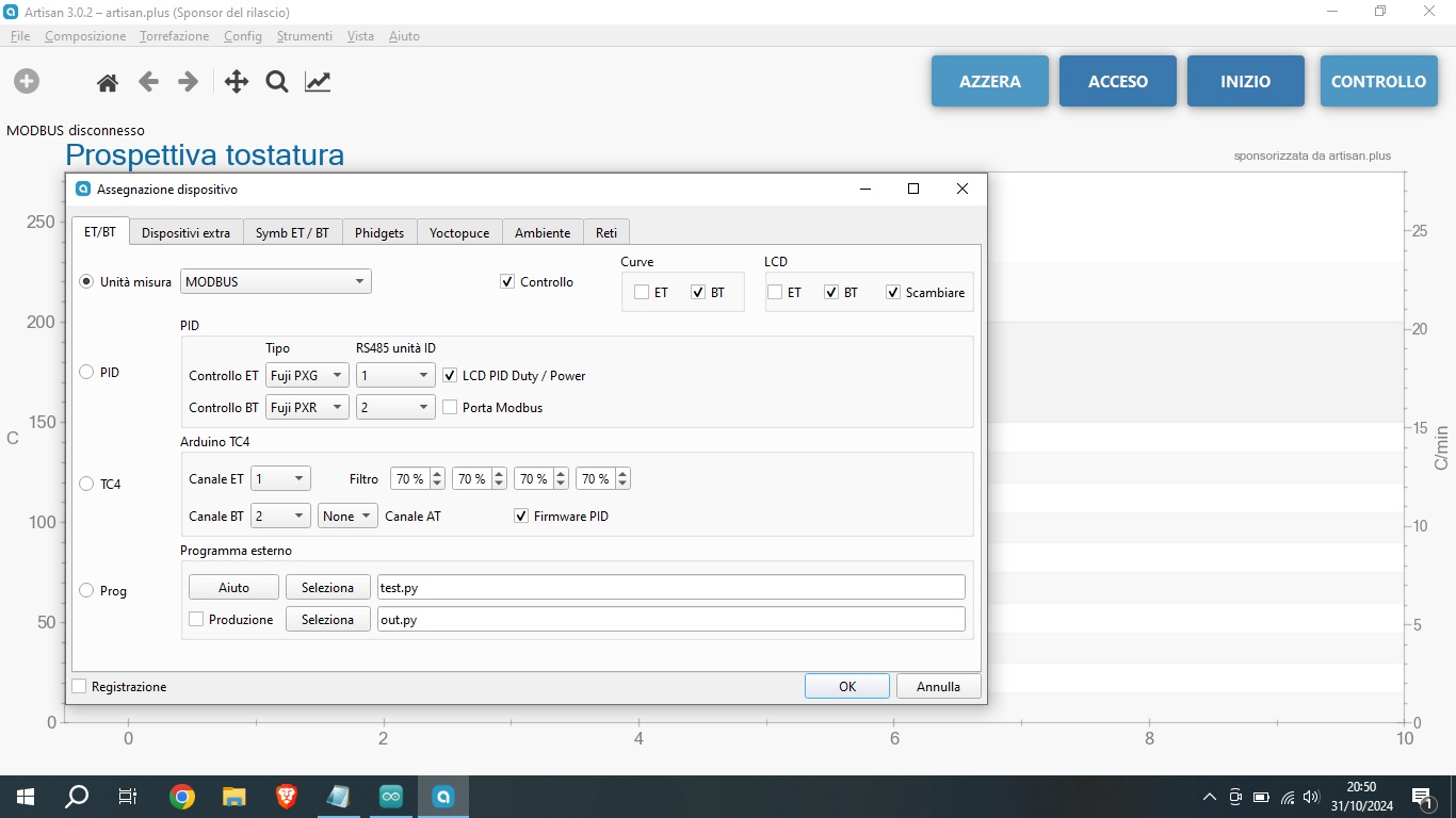
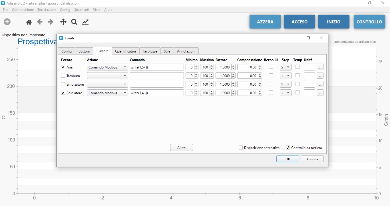
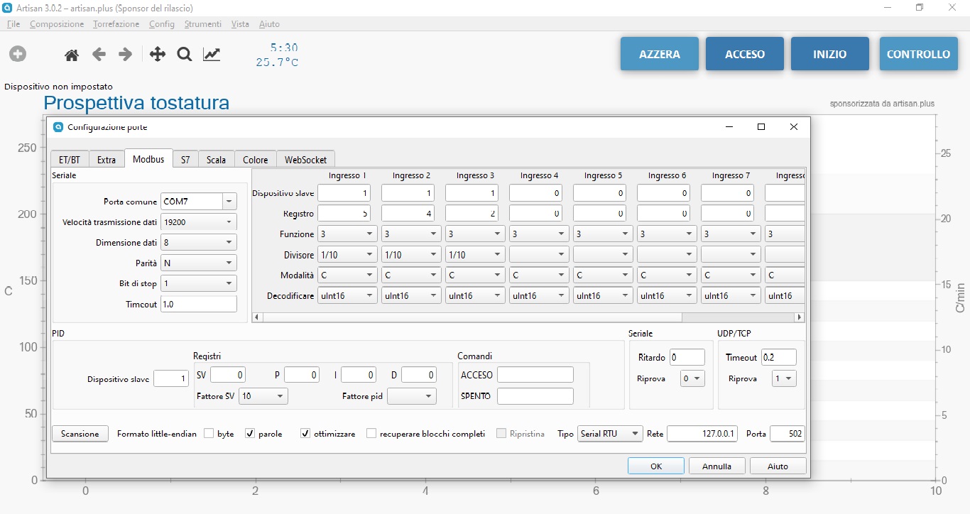
First... show us the Artisan screen with modbus configuration. From the code, I guess that register 2 is for temperature, and register 4 for heater. Similar to register 4, you should map in Artisan another register, for fan, say register 5... and in this case, instead the actual ESC mapping and control code... Code Download source potValue = map(potValue, 0, 1023, 0, 180); // scale it to use it with the servo library (value between 0 and 180) you will have ... Code Download source potValue = map(au16data[5], 0, 100, 0, 180); // scale it to use it with the servo library (value between 0 and 180) |
|
|
|
| Seroastito |
Posted on 10/31/2024 3:09 PM
|
|
Newbie  Posts: 10 Joined: October 26, 2024 |
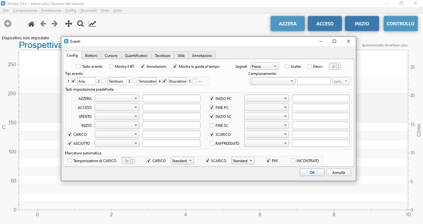
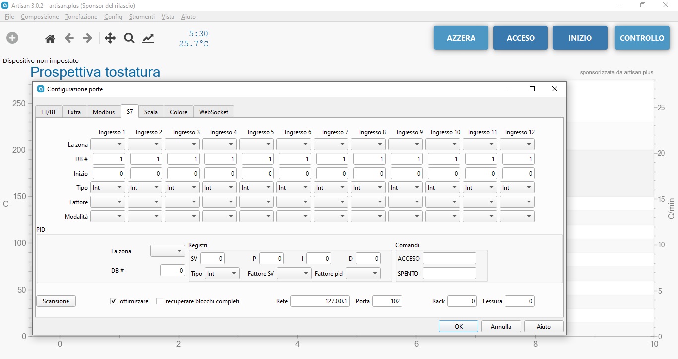
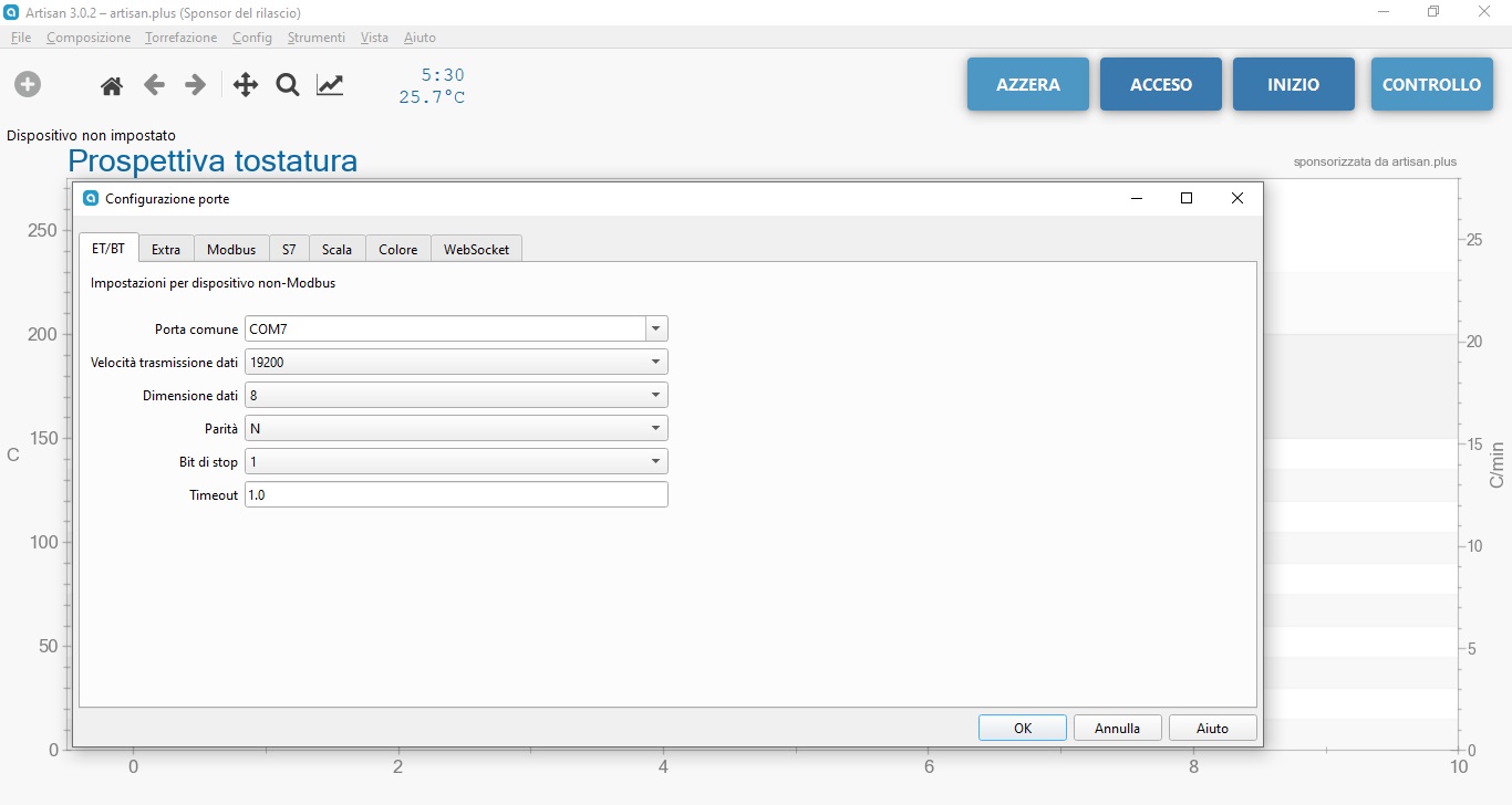
Quote renatoa wrote: First... show us the Artisan screen with modbus configuration. From the code, I guess that register 2 is for temperature, and register 4 for heater. Similar to register 4, you should map in Artisan another register, for fan, say register 5... and in this case, instead the actual ESC mapping and control code... Code Download source potValue = map(potValue, 0, 1023, 0, 180); // scale it to use it with the servo library (value between 0 and 180) you will have ... Code Download source potValue = map(au16data[5], 0, 100, 0, 180); // scale it to use it with the servo library (value between 0 and 180) You are a genius!!! As soon as I got home I entered the code as you suggested and it worked! Now I have to refine it a bit because the motor responds after about 5 seconds, after each command and this is a problem for a PID roasting LOL. The temperature probe does not show any value. And when I have the SSR available again (tomorrow or the day after tomorrow), I will verify that it works correctly. I attach the photos of Artisan and the new code that allows me to control the brushless motor. Thank you so much again! Code Download source #include <max6675.h>
Seroastito attached the following images:
|
|
|
|
| Seroastito |
Posted on 11/03/2024 1:48 AM
|
|
Newbie  Posts: 10 Joined: October 26, 2024 |
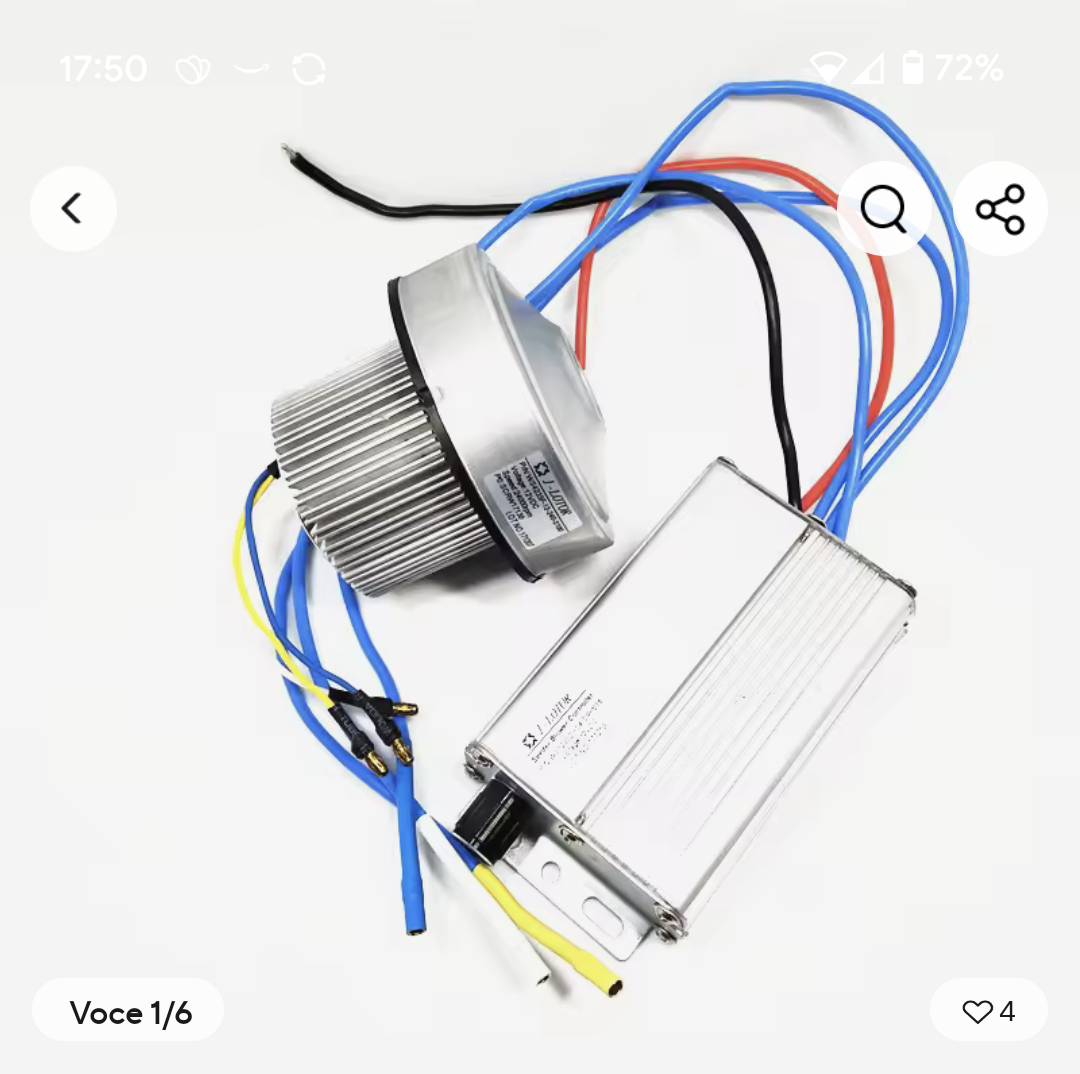
Finally I connected everything and everything works, the brushless run, the temperature is right and the SSR works fine. Now I just need to find the right brushless fan. I found some brushless blower and vacuum brushless fan with ESC integrated, but my doubt is: can I controll this ESC/motor with Arduino?? Do you have any experiences with these products? https://a.aliexpr...m/_EzAKyCH https://a.aliexpr...m/_EIyjyJx https://a.aliexpr...m/_EzX9T8Z https://a.aliexpr...m/_EHfcnhL |
|
|
|
| renatoa |
Posted on 11/03/2024 12:36 PM
|
|
Administrator  Posts: 3192 Joined: September 30, 2016 |
These are no more model plane motors, thus the control timing is unknown, probably not servo style. If you don't have exact intel about the control PWM specs, they are a lottery. |
|
|
|
| Seroastito |
Posted on 11/03/2024 12:44 PM
|
|
Newbie  Posts: 10 Joined: October 26, 2024 |
Quote renatoa wrote: These are no more model plane motors, thus the control timing is unknown, probably not servo style. If you don't have exact intel about the control PWM specs, they are a lottery. You are right, I would like to buy a 2200kvengine and 12V 20A power supply but I can't find a suitable fan to replace the popper one... one last thing do you by any chance know how I can increase the reactivity of the engine? Responds after 3-5 seconds. |
|
|
|
| renatoa |
Posted on 11/03/2024 12:50 PM
|
|
Administrator  Posts: 3192 Joined: September 30, 2016 |
For reactivity increase SLEW_STEP. The popper motor has 8-12000 RPM, depending on build. Probably 2200kv would suit you, if using 12V... will run around 50% throttle. Why replace the fan? Get a 2.3mm shaft motor and use same fan. |
|
|
|
| Seroastito |
Posted on 11/04/2024 5:30 AM
|
|
Newbie  Posts: 10 Joined: October 26, 2024 |
In the end I ordered, a 2200kv brushless, 40A Power supply and will see what comes out! I will keep you updated, in the meantime thank you very much for all your valuable advice! |
|
|
|
| renatoa |
Posted on 11/04/2024 8:33 AM
|
|
Administrator  Posts: 3192 Joined: September 30, 2016 |
Good point about power supply capable of great amperage... you should expect a draw in the 8-10 Amps ballpark. The popper motors current is around 3 Amps, from 24V sources. Please also note that the model plane motors aren't designed to run continuously, many minutes, at constant power, except those used in drones. Even drone motors are used 90% of time in the 40-60% throttle range. For cheap motors consider the bearings life somewhere in the tens of hours range, not so many... I had broken bearings even after 10 hours. They are cheap and simply to replace though... |
|
|
|
| Seroastito |
Posted on 11/04/2024 11:07 AM
|
|
Newbie  Posts: 10 Joined: October 26, 2024 |
Quote renatoa wrote: Good point about power supply capable of great amperage... you should expect a draw in the 8-10 Amps ballpark. The popper motors current is around 3 Amps, from 24V sources. Please also note that the model plane motors aren't designed to run continuously, many minutes, at constant power, except those used in drones. Even drone motors are used 90% of time in the 40-60% throttle range. For cheap motors consider the bearings life somewhere in the tens of hours range, not so many... I had broken bearings even after 10 hours. They are cheap and simply to replace though... This engine that I have bought appears to be one of the cheap ones, I build this roast more as a hobby and to try roasted coffee with the air, because my main roast is the Kaleido M2 Pro, and the BocaBoca250. Considering that the maximum quantity I want to roast is 100gr, I hope to use it at maximum 50% throttle. Then there is the problem of the limit of 1200W of the heater. I really hope it is enough for me, otherwise I would not know what to use... https://share.tem...Y98reTQSlA Edited by renatoa on 11/04/2024 12:19 PM |
|
|
|
| Seroastito |
Posted on 11/05/2024 8:10 AM
|
|
Newbie  Posts: 10 Joined: October 26, 2024 |
I could not resist and today I tried to do roast the first 60grams of Honduras (cheap coffee). I definitely went beyond the first crack and lost 18%, but the goal is not to drink it but to verify that everything is working correctly! First Crack at 198°C, I forgot to crush charge button on Artisan but the important thing is that everything is recorded. Artisan Lower or turn up the engine revs 5 seconds after my command unfortunately ... We will see how it goes with the new brushless engine and the pyrex glass.  Please, change the image links as I did above, pointing each to the jpg files, and enclosed in img tags. https://ibb.co/B46Hy9P https://ibb.co/h9sNds6 https://ibb.co/dc92wKH https://ibb.co/fxJ5ShZ Edited by renatoa on 11/05/2024 12:13 PM |
|
|
|
| renatoa |
Posted on 11/05/2024 12:09 PM
|
|
Administrator  Posts: 3192 Joined: September 30, 2016 |
You can mark events later, after the roast, just right click on the curve, at desired time, and add event to place there. Why not drink?  |
|
|
|
| Seroastito |
Posted on 11/05/2024 12:35 PM
|
|
Newbie  Posts: 10 Joined: October 26, 2024 |
Quote renatoa wrote: You can mark events later, after the roast, just right click on the curve, at desired time, and add event to place there. Why not drink?  Degassing! 😅 Saturday I will absolutely try it with the super Cafelat Robot! |
|
|
|
| Jump to Forum: |
Powered by PHP-Fusion Copyright © 2024 PHP-Fusion Inc
Released as free software without warranties under GNU Affero GPL v3
Designed with ♥ by NetriXHosted by skpacman


