
Login

Shoutbox
You must login to post a message.
allenb
09/15/2024 8:05 PM
JKnight 
renatoa
09/15/2024 1:26 AM
JonnyPanic,  ?
?
?renatoa
09/13/2024 1:32 PM
Krush and jdspainhour,

renatoa
09/12/2024 1:06 AM
 , KnittyBrew
allenb
09/10/2024 1:55 PM
Welcome to all new HRO members!!!

Forum Threads
Newest Threads
Hello from eastern PAUsing a TC4 with Art...
Skywalker roaster mods
Skywalker Roasts
My Sight Glass FB Ro...
Hottest Threads
| Skywalker roaster... | [386] |
| Skywalker Roasts | [102] |
| War on Farmers by... | [53] |
| Using a TC4 with ... | [41] |
In Memory Of Ginny

Donations
Latest Donations
dmccallum - 10.00
JackH - 25.00
snwcmpr - 10.00
Anonymous - 2.00
Anonymous - 5.00
dmccallum - 10.00
JackH - 25.00
snwcmpr - 10.00
Anonymous - 2.00
Anonymous - 5.00
Users Online
Guests Online: 3
Members Online: 0
Total Members: 8,494
Newest Member: JKnight
Members Online: 0
Total Members: 8,494
Newest Member: JKnight
View Thread
Who is here? 2 guest(s)
 4-channel TC meter and datalogger project
|
|
| bvwelch |
Posted on 07/16/2010 8:38 AM
|
 1 1/2 Pounder  Posts: 1064 Joined: December 27, 2007 |
Allen, In order to 'flash' the program into the Arduino, you'll need to plug into the USB, which provides the power during that operation. For standalone operation, it looks like the barrel-jack is a good approach: http://www.arduin...eryAdapter |
|
|
|
| allenb |
Posted on 07/16/2010 9:16 AM
|
 Administrator Posts: 3885 Joined: February 23, 2010 |
I'm glad to hear the barrel plug is a good option for the 9V battery. Another question, This link: http://arduino.cc/en/uploads/Tutorial/lcd_bb.png shows Arduino 5V to LCD pin 2, GND to LCD pins 1 and 5, pot wiper to LCD pin 3. I'm assuming with the latest pin config this has changed? Randy, thanks for the clarification on the backlight versus contrast for LCD. I'm confident that your download/upload instructions are good. It's my impatient tendency to jump ahead I'm worried about. Allen Edited by allenb on 07/16/2010 9:20 AM 1/2 lb and 1 lb drum, Siemens Sirocco fluidbed, presspot, chemex, cajun biggin brewer from the backwoods of Louisiana
|
|
|
|
| bvwelch |
Posted on 07/16/2010 9:22 AM
|
|
1 1/2 Pounder Posts: 1064 Joined: December 27, 2007 |
Hi Allen, While the data-bit definitions have in fact changed, the pins you mentioned above are for power and contrast and they have not changed. In fact, if you just hook up the above, you could be able to adjust the contrast on the LCD and see black squares come and go as you adjust the knob. See JimG's doc here: http://code.googl...loads/list Edited by bvwelch on 07/16/2010 9:26 AM |
|
|
|
| randytsuch |
Posted on 07/16/2010 10:26 AM
|
 1/2 Pounder  Posts: 394 Joined: June 20, 2009 |
Now that I have I have working LCD, I think the next step is to add some type of keypad/input device, and to start looking at creating a PID. I found this http://www.instru...gram-code/ There are other links I found for making a PID for an espresso machine, most with a Silvia. One guy wrote a PID library for the Arduino, which I think is the standard way to implement a PID now. The thing about the link above, the guy is controlling the temp mostly with airflow, and only controlling the heat if it gets too hot. I have a modded popper, and am also planning to control airflow, but in the first version, I was just going to control the heater, and manually adjust airflow (my current scheme). This will also make it more universal, for people who don't care about airflow control. So, I would need to port in the temp input code, and change the heater output. The code also has user input, which I don't have yet. It's been a while since I programmed, so we'll see if I can figure this out. Randy |
|
|
|
| allenb |
Posted on 07/16/2010 10:42 AM
|
|
Administrator Posts: 3885 Joined: February 23, 2010 |
Thanks Bill, that clears up the LCD. After building the shield, I think some construction tips might be in order, specifically in the area of soldering. The MCP9800 is the smallest thing I've ever tried to solder and I thought I'd never get it to sit still. When trying to hold it down with tweezers or sharp tipped awl it likes to scoot about due to the slick tinned pads on the shield. What finally worked was to hold my breath and applying the tip of my iron to one of its legs which melts the tinned pad solder enough to hold it in place for the rest of the soldering. I got it done but its not as pretty as I'd like. Also, it's good to tack a pin on one side then another on the other side to not have the chip tipped up on one side. Without my 5X visor I would not have been able to see it well enough to solder. In fact, next time with something this small I'll probably use a 10X. One problem with the surface mount chips was my solder. Its .030" dia which is too thick for this delicate of an operation. .015" seems to be less clumsy with less chances for bridging. My iron is 15 watts but its tip was not fine enough. I carefully ground it down to a fairly small point but not all the way to a sharp point. One guy I talked to who builds with SMT regularly by hand said he cheats and uses a fat tip and just solders the whole side at one time with it bridging across the pins then uses a solder wick to remove the bridges. I didn't feel like experimenting on the shield. Has anyone used this technique? Allen 1/2 lb and 1 lb drum, Siemens Sirocco fluidbed, presspot, chemex, cajun biggin brewer from the backwoods of Louisiana
|
|
|
|
| bvwelch |
Posted on 07/16/2010 12:38 PM
|
|
1 1/2 Pounder Posts: 1064 Joined: December 27, 2007 |
Hi Allen, there is a lot of info scattered on this thread so I'm guessing you didn't see my crude video doing just what you described above? I've added it to the BuildIt notes on the wiki also. http://bvwelch.co... Actually I hope some one will replace it with a much better one. You can't see much. Sparkfun has some good videos of SMT soldering techniques. Edited by bvwelch on 07/16/2010 12:40 PM |
|
|
|
| allenb |
Posted on 07/16/2010 12:56 PM
|
|
Administrator Posts: 3885 Joined: February 23, 2010 |
Bill, I had viewed the video but didn't connect your use of the wick with the process. Are there any caveats to beware of when using the technique? (besides not overheating the chip). 1/2 lb and 1 lb drum, Siemens Sirocco fluidbed, presspot, chemex, cajun biggin brewer from the backwoods of Louisiana
|
|
|
|
| allenb |
Posted on 07/16/2010 3:56 PM
|
|
Administrator Posts: 3885 Joined: February 23, 2010 |
Need help with an issue with uploading to the Arduino. After hitting "upload to I/O board" I am getting an error message that reads: C:\Docume-1\ALLENB-1\LOCALS-1\Temp\build4781293514866854556.tmp\core.a(main.cpp.o) : In function 'main' : Then reads: C:\Program files\arduino-0018\hardware\aduino\cores\arduino/main.cpp:7: undefined reference to 'setup'. Then reads just like the above but ends with undefined reference to 'loop' I looked in the troubleshooting guide but didn't see anything similar. Everything seemed to download just fine to C: program files. Allen 1/2 lb and 1 lb drum, Siemens Sirocco fluidbed, presspot, chemex, cajun biggin brewer from the backwoods of Louisiana
|
|
|
|
| randytsuch |
Posted on 07/16/2010 5:24 PM
|
|
1/2 Pounder Posts: 394 Joined: June 20, 2009 |
I don't remember seeing errors like that. Did you try running the simple "blink" program, and did that work OK? Can you compile aBourbon without errors (without loading it)? Randy |
|
|
|
| allenb |
Posted on 07/16/2010 5:43 PM
|
|
Administrator Posts: 3885 Joined: February 23, 2010 |
Quote randytsuch wrote: I don't remember seeing errors like that. Did you try running the simple "blink" program, and did that work OK? Can you compile aBourbon without errors (without loading it)? Randy Yes, blink worked fine. I went ahead and am trying to unzip the bourbon at present. ( I might need some bourbon pretty soon). I need some help with the unzipping to the correct location. What has me hung up is where the instructions state: THIS IS IMPORTANT, program won?t work if it?s not in the right place Delete the ?bourbon2010XXXX? at the end, and extract into the ?my documents? subdirectory (Note: XXXX is the month and day of the build date). Should I simply change the date shown to todays date and leave all else as-is when the extraction dialogue box comes up or is there more to the "subdirectory" mentioned. Not clear on what to write here. Thanks for the help. 1/2 lb and 1 lb drum, Siemens Sirocco fluidbed, presspot, chemex, cajun biggin brewer from the backwoods of Louisiana
|
|
|
|
| bvwelch |
Posted on 07/16/2010 5:56 PM
|
|
1 1/2 Pounder Posts: 1064 Joined: December 27, 2007 |
Hi Allen, The name/date of the zip file doesn't matter. That just helps us keep track of which version you downloaded. I just downloaded the file: bourbon20100710b.zip You can unzip it to anyplace -- it doesn't matter. Now then, simply drag and drop (move) the contents of the extracted zip file into your 'My Documents' folder. Once you are done, you should find files like this (I'm just listing a few to give you the idea): My Documents\Arduino\aBourbon\aBourbon.pde and My Documents\Processing\pBourbon\pBourbon.pde -bill Edited by bvwelch on 07/16/2010 5:59 PM |
|
|
|
| randytsuch |
Posted on 07/16/2010 6:31 PM
|
|
1/2 Pounder Posts: 394 Joined: June 20, 2009 |
Or, if you unzip to ?C:\Documents and Settings\your name\My Documents? it will create the arduino and processing directories in my documents, and you should be set. That is what I was trying to say in my instructions, I guess it wasn't clear. Randy |
|
|
|
| allenb |
Posted on 07/16/2010 9:29 PM
|
|
Administrator Posts: 3885 Joined: February 23, 2010 |
Quote randytsuch wrote: Or, if you unzip to ?C:\Documents and Settings\your name\My Documents? it will create the arduino and processing directories in my documents, and you should be set. That is what I was trying to say in my instructions, I guess it wasn't clear. Randy Wow, what an adventure! It's up and running. Thanks Randy and Bill for all the help. I finally dumped everything and had my wife start from scratch. Naturally it worked perfectly when she did the down/up loading. She has always accused me of being computer challenged. In all seriousness, I'm using Firefox which does create some problems when unzipping things. When saving zipped files it sometimes likes to unzip while saving to the folder instead of saving it in a zipped form. I was "over thinking" things which sometimes gets me into trouble. One more thing, While downloading the program files I took a little time examining the software you guys wrote. All I can say is this is a whole lot more software writing than I thought this RoR would take to do what it does. I have a greater appreciation for the effort it took in creating the shield software. Maybe this is a piece of cake compared to what you do in your day job but looks pretty impressive. Thanks, Allen 1/2 lb and 1 lb drum, Siemens Sirocco fluidbed, presspot, chemex, cajun biggin brewer from the backwoods of Louisiana
|
|
|
|
| allenb |
Posted on 07/17/2010 3:12 PM
|
|
Administrator Posts: 3885 Joined: February 23, 2010 |
LCD question: Once we establish the resistance needed between LCD pins 2 and 3 via potentiometer to gain good contrast, can we just substitute a fixed resistor between the two pins? Or, does contrast shift over time making it necessary to adjust in the future? I'm not liking having to find a home for the pot. Edited by allenb on 07/17/2010 3:13 PM 1/2 lb and 1 lb drum, Siemens Sirocco fluidbed, presspot, chemex, cajun biggin brewer from the backwoods of Louisiana
|
|
|
|
| allenb |
Posted on 07/18/2010 11:49 AM
|
|
Administrator Posts: 3885 Joined: February 23, 2010 |
Quote allenb wrote: LCD question: Once we establish the resistance needed between LCD pins 2 and 3 via potentiometer to gain good contrast, can we just substitute a fixed resistor between the two pins? Or, does contrast shift over time making it necessary to adjust in the future? I'm not liking having to find a home for the pot. Ok, I established that I needed 10K on the pot for optimum contrast. I tried to just insert a 10K resistor between pins 2 and 3 of the LCD but no go. I had to replicate what the pot was doing with a ground also going to pin 3 (LCD). You would think this would drop pin 3 to zero volts and be the same as not having any contrast circuitry at all but it works perfectly with my setup. Not guaranteeing this is good for other LCD's but seems to work on mine. If anyone sees a potential negative consequence with this please let me know. The drawing here is just to show the resistor versus potentiometer hookup. The rest of the circuit does not reflect the current wiring layout.
allenb attached the following image:
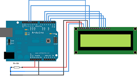
Edited by allenb on 07/18/2010 11:52 AM 1/2 lb and 1 lb drum, Siemens Sirocco fluidbed, presspot, chemex, cajun biggin brewer from the backwoods of Louisiana
|
|
|
|
| allenb |
Posted on 07/18/2010 1:12 PM
|
|
Administrator Posts: 3885 Joined: February 23, 2010 |
Quote allenb wrote: Ok, I established that I needed 10K on the pot for optimum contrast. I tried to just insert a 10K resistor between pins 2 and 3 of the LCD but no go. I had to replicate what the pot was doing with a ground also going to pin 3 (LCD). You would think this would drop pin 3 to zero volts and be the same as not having any contrast circuitry at all but it works perfectly with my setup. Alright, A Duh moment. I should consider ohms law now and then. As it turns out all I did was establish LCD pin 3 to ground. I had read somewhere that in some cases this sets up acceptable contrast and does so at least with my LCD. Sorry for displaying the useless parts of my experimenting. Allen 1/2 lb and 1 lb drum, Siemens Sirocco fluidbed, presspot, chemex, cajun biggin brewer from the backwoods of Louisiana
|
|
|
|
| randytsuch |
Posted on 07/19/2010 1:11 AM
|
|
1/2 Pounder Posts: 394 Joined: June 20, 2009 |
So I worked on a PID program over the weekend. I got it working, except that the PWM doesn't really work with my SSR, I think the PWM frequency is too fast. Net result is I get very large temp swings in ET, but it does track a profile. I am thinking about just making it based on duty cycle, and run it at either 25%, 50%, 75% or 100%. Randy |
|
|
|
| bvwelch |
Posted on 07/19/2010 9:29 AM
|
|
1 1/2 Pounder Posts: 1064 Joined: December 27, 2007 |
Hi Randy, Cool! But I can't say more without more specific details. If you want to put your project up in the SVN or even just upload a zip file we could take a look-see. I haven't looked at Jim's PWM library yet but I think it is variable over a wide range. -bill |
|
|
|
| JimG |
Posted on 07/19/2010 11:08 AM
|
|
1 1/2 Pounder Posts: 834 Joined: October 23, 2008 |
Randy The PWM16 library has capability for fixed time bases of up to 4 seconds. Jim |
|
|
|
| Dan |
Posted on 07/19/2010 2:25 PM
|
|
1 1/2 Pounder Posts: 1662 Joined: October 24, 2005 |
Duty cycle? I think what you mean is setting up a percentage timer. That's what my sample roaster uses for manual heat control. I use a pot to vary the on/off cycle from 0-100%, with the cycle being 10s long. You will want continuous control. Four steps just doesn't give you the control you need. I would recommend a 1-2 second cycle for smoother heat output. |
|
|
|
| randytsuch |
Posted on 07/19/2010 2:52 PM
|
|
1/2 Pounder Posts: 394 Joined: June 20, 2009 |
Quote bvwelch wrote: Hi Randy, Cool! But I can't say more without more specific details. If you want to put your project up in the SVN or even just upload a zip file we could take a look-see. I haven't looked at Jim's PWM library yet but I think it is variable over a wide range. -bill OK, I will upload the latest version of my SW. I just added Jim's PWM16 library into my code, but I have not tested that version, just made sure it compiles. You guys also have to promise not to laugh at my programming. I never did a lot, and whatever skills I have are pretty rusty, although it is starting to come back to me. I made some changes, like RoR for both temps. Set T1 to ET, and T2 to BT, although that can easily be changed. Reformatted LCD slightly. I have a 4x20 LCD, so I am using the extra space to output other parameters, to help troubleshoot the program, it's nice to see the extra information. I think PWM16 has a range of 0-100, so that's how my code is written now, as opposed to the Arduino PWM, which has a range of 0-255. Randy |
|
|
|
| randytsuch |
Posted on 07/19/2010 11:38 PM
|
|
1/2 Pounder Posts: 394 Joined: June 20, 2009 |
I set the PWM output to 4 Hz, and it is working nicely  . .Without really tweaking the PID parameters, I was really pleased with the performance. It is not easy to keep a smooth looking ET in a popper (no thermal mass to help smooth things out), but the graph looked pretty good. I don't have BT connected yet, I had it connected to a meter, I plan to connect it tomorrow, and wire a switch to the heater control, so I have a manual override on the heat, and I'm ready to try a real roast on this. BTW, the roast I did today was meant for the trash, but it still looked pretty good. I let it go too long, to make sure the termination logic worked, and it still looked good. Randy |
|
|
|
| JimG |
Posted on 07/19/2010 11:39 PM
|
|
1 1/2 Pounder Posts: 834 Joined: October 23, 2008 |
Quote randytsuch wrote:I think PWM16 has a range of 0-100, so that's how my code is written now, as opposed to the Arduino PWM, which has a range of 0-255. Correct. PWM16 is written to provide 0% to 100% output with a resolution of 1%. The resolution available on the timer, however, is a full 16-bit. So if you think there is a need for higher resolution, I'll be happy to add a function to provide it. Jim |
|
|
|
| JimG |
Posted on 07/19/2010 11:53 PM
|
|
1 1/2 Pounder Posts: 834 Joined: October 23, 2008 |
Quote randytsuch wrote: BTW, I had one comment for you, on the LCD pin list. It would be helpful to include the POT wiring in that file, it's the only thing missing, to connect the LCD. Sorry to be a little slow to respond. I've been spending most of my time in the Colorado backcountry the last 10 days I've uploaded (to the googlecode project site) a revised version of the pin assignments for the TC-4 shield. This revised list includes some information on the POT wiring, as well as a glimpse at current thinking for a V2.0 of the TC-4 shield. http://tc4-shield...ns-rev.pdf For those interested in the direction the V2.0 design is moving, feel free to browse through the SVN portion of the googlecode site and have a look in the hardware/sandbox area. http://code.googl...re/sandbox Jim Edited by JimG on 07/20/2010 1:01 AM |
|
|
|
| randytsuch |
Posted on 07/20/2010 9:05 AM
|
|
1/2 Pounder Posts: 394 Joined: June 20, 2009 |
Quote JimG wrote: Quote randytsuch wrote:I think PWM16 has a range of 0-100, so that's how my code is written now, as opposed to the Arduino PWM, which has a range of 0-255. Correct. PWM16 is written to provide 0% to 100% output with a resolution of 1%. The resolution available on the timer, however, is a full 16-bit. So if you think there is a need for higher resolution, I'll be happy to add a function to provide it. Jim Thanks Jim I rescale the output of the pid program to a 0-100 range, and it seems to be working fine. Luckily the guy who wrote the roaster program had to do this too, so I just copied his use of the map function. Randy |
|
|
|

| Jump to Forum: |
Powered by PHP-Fusion Copyright © 2024 PHP-Fusion Inc
Released as free software without warranties under GNU Affero GPL v3
Designed with ♥ by NetriXHosted by skpacman