
Login

Shoutbox
You must login to post a message.
renatoa
05/18/2024 4:18 AM
Tech2C, 
renatoa
05/17/2024 11:29 AM
 jhondue
renatoa
05/16/2024 2:02 AM
Dbic and buddy_magi,
 ?
?
?allenb
05/15/2024 5:30 PM
buorus

renatoa
05/14/2024 7:01 AM
 , kazozero
Forum Threads
Newest Threads
New to roasting. Co...Skywalker Roasts
Skywalker, the ALM c...
Roasting Peru Washed
Skywalker bearing ch...
Hottest Threads
| Skywalker roaster... | [320] |
| Skywalker, the AL... | [235] |
| Skywalker Roasts | [97] |
| War on Farmers by... | [41] |
| Understanding the... | [29] |
In Memory Of Ginny

Donations
Latest Donations
dmccallum - 10.00
JackH - 25.00
snwcmpr - 10.00
Anonymous - 2.00
Anonymous - 5.00
dmccallum - 10.00
JackH - 25.00
snwcmpr - 10.00
Anonymous - 2.00
Anonymous - 5.00
Users Online
Guests Online: 2
Members Online: 0
Total Members: 8,269
Newest Member: Tech2C
Members Online: 0
Total Members: 8,269
Newest Member: Tech2C
View Thread
Who is here? 1 guest(s)
Page 1 of 2: 12
|
 Yet Another 250g-500gm FB Roaster
|
|
| PhilH |
Posted on 09/23/2015 12:56 AM
|
 Newbie  Posts: 47 Joined: September 10, 2015 |
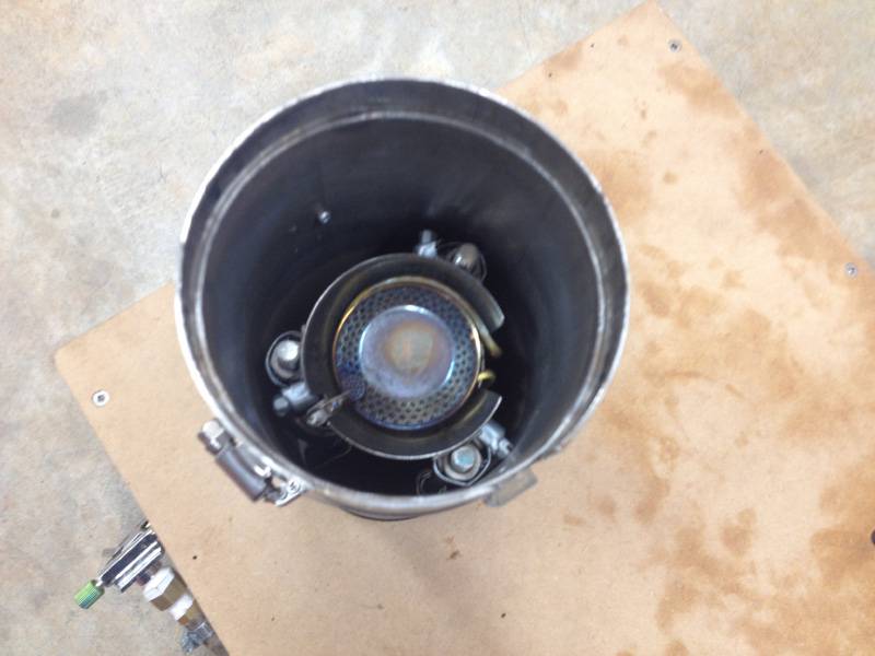
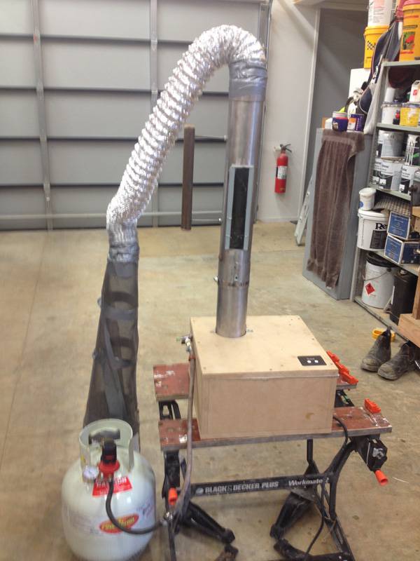
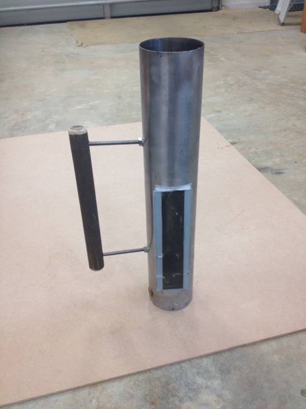
I have been making espresso's on a variety of machines for many years and current home setup is DallaCorte Mini / K10Fresh. I am new to roasting but I was inspired to build a roaster after talking to a friend who uses a breadmaker / heat gun manual roaster. After looking at the incredible number of amazing roasters on this site I decided decided on a LPG fired FB roaster. I hope to be able to do 250g to 1kg batches. I liked the look of AllenBs and Omegas and Tamarians FB roasters and that will account for the similarities (ie stealing their great ideas). Mine consists of: RC - S/Steel Pipe 98mm dia (ID) x550mm x1.8mm (W.T.) from recycler Diffuser plate ? 1.8mm S/Steel with separate ramp (copied from Omegas design) Blower - Panasonic 1000W VC blower (free) Fan Speed - 3000W triac / voltage/speed controller (http://www.tradem...=948769066) Burn Chamber/Coupling - S/S Pipe as above Burner - LPG Camping Stove mushroom style burner c/w needle valve (http://www.marine...tion-stove) 0-55psi LPG Gas Regulator Customwood box ? homemade Chaff Collector ? copied from Tamarians design The blower is overpowered and will lift 1.5 ? 2kg kg of beans and will lift the empty RC off the burn chamber at 100% speed I run it at 25-30% for 250g load of green beans The burner was problematic as it was designed to screw directly onto a camping LPG canister. I managed to get an adapter and connect this to a standard bbq fixed pressure regulator and connected to a 9kg LPG gas bottle. It was hopeless. I discovered the std non adjustable regulators are factory set at approx 1/5 psig which barely stayed alight with needle valve wide open. I got a 0-55psi LPG regulator which was great when set at about 20-25psig. I drilled out the jet to 0.4mm and am now running at about 12psig with plenty of power and control. The needle valve / piezo is connected to the burner with about 10? of very thin braided flexible tubing which is difficult to mount elegantly outside the box (see photos) Burner tests ok - stable flame at all fan speeds I wanted to view the beans during the roast so made a glass viewing chamber using standard 5mm glass and high temp sealant. I also made a small flame viewing hole in roast chamber. The standard glass unfortunately has cracked during the first roast :( I am new to roasting so I am on a steep learning curve as far as the actual roasting goes. I am starting with just a simple Multimeter/K-Type Thermocouple to measure BT, a stopwatch and tweaking the needle valve and blower speed and a rudimentary profile to aim at. I bought a variety of SO green beans and the importer kindly gave me a couple of kg of old rubbishy beans for roaster testing The first roast was a shocker ? 23psig gas, 7mins, color looks ok but beans smell burnt. The only good outcome was I confirmed the beans will cool in the RC to under 40C in less than 2 minutes Second roast ? lowered LPG pressure to 15psig 9mins total - the beans a bit lighter, but still dont smell or taste good 3rd roast = no preheat, 8psig ? 18minutes 4th roast ? preheat BT to 150C, 12psig total 12 minutes ? FC 190C at 8:30 - a little dark but this is starting to smell a bit like coffee Im finding it difficult to control the roast temp profile and Im running out of rubbishy beans. I dont want to waste good quality beans while I learn how to roast. I may need to upgrade to a live temp logging setup. Maybe a TC4/aArtisan type setup ? Any advice much appreciated Pics below. Regds Phil ps many thanks for all the great ideas on the other builds
PhilH attached the following images:


|
|
|
|
| allenb |
Posted on 09/23/2015 11:04 PM
|
 Administrator Posts: 3861 Joined: February 23, 2010 |
Hi Phil and big welcome to HRO! You've got a beautiful build there! You'll be roasting some excellent coffee in that rig in no time. A couple of suggestions. One, definitely get your hands on a TC4 or parts to build one so you can have the benefit of seeing real time rate of rise. At this point in time that's all I use and don't bother datalogging unless I'm in some type of experimentation mode otherwise just jotting down a few milestones is all you need to get your profiles figured out. Keep it simple! Two, spend some quality time examining threads dealing with profile best practice to get a good idea where to start to keep you from fouling up a lot of quality green coffee while getting the hang of things. Keep us posted on progress and I'm sure others will jump in with some good profile pointers. Cheers, Allen 1/2 lb and 1 lb drum, Siemens Sirocco fluidbed, presspot, chemex, cajun biggin brewer from the backwoods of Louisiana
|
|
|
|
| PhilH |
Posted on 10/13/2015 10:55 PM
|
|
Newbie Posts: 47 Joined: September 10, 2015 |
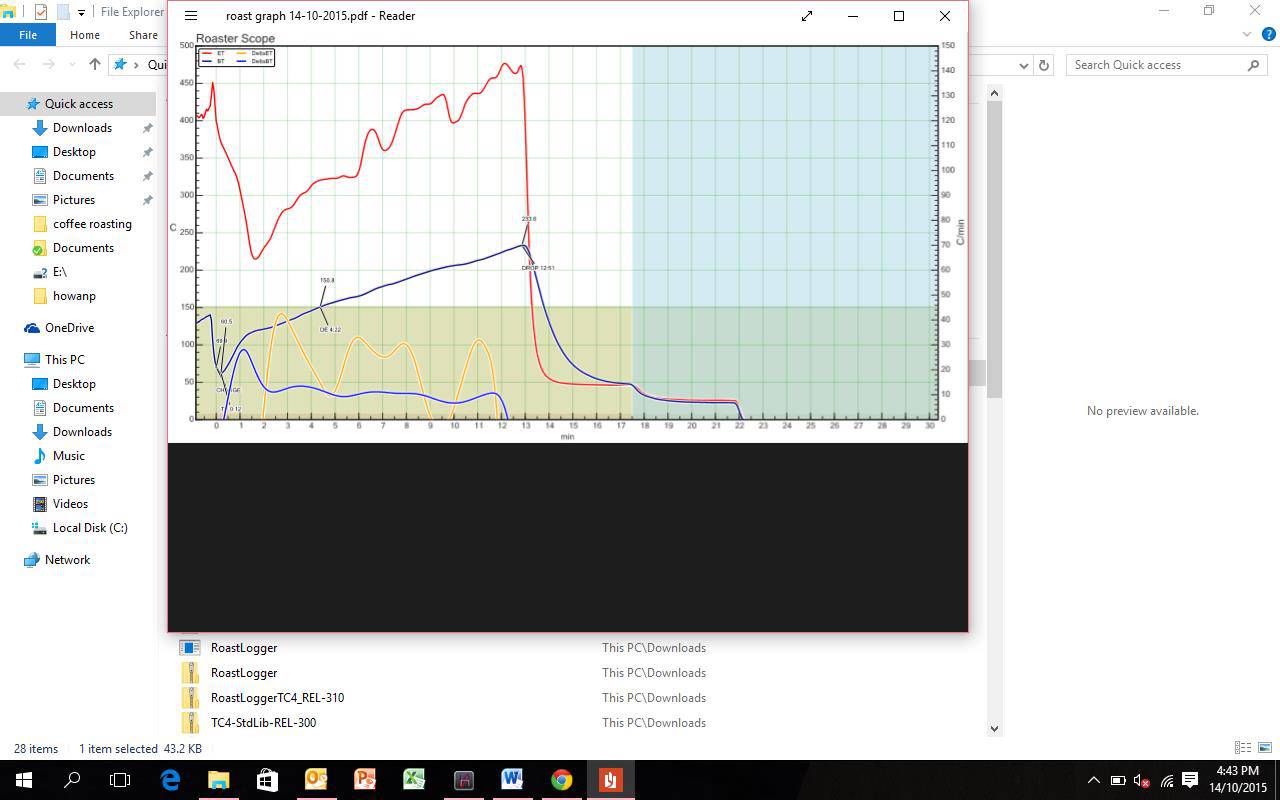
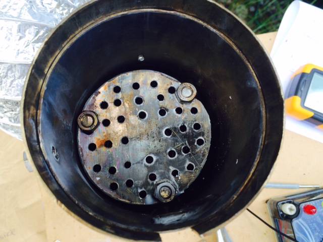
Ok ? so Ive made some progress - Replaced broken sightglass with toughened glass - Installed a arduino / TC4 / aArtisanQ_PID / Artisan Roast Scope setup - I have LCDapter but still waiting for 4x20LCD module to arrive so currently operating using Artisan Roast Scope - Modified Box to reduce noise from VC motor ? repositioned VC motor and added partitions in box so suction path to VC has a couple of 90deg turns before arriving at VC ET temp seems to be running way too high c/w BT (ie 150-200C higher than BT and Im not sure why. I have lowered my burner in the burner tube and installed a burner diffusion plate which has helped a bit but still seems high see attached Artisan Scope pic. I have currently 35x 3.2mm holes in RC diffusion plate. I am still learning the ropes as far as the actual roasting goes and Im finding it hard to pick FC, So Im probably roasting a bit too long before drop. Attached some pics and graph from todays roast 440g green, 370g roasted 10psig gas, note the high ET Comments and advice most welcome |
|
|
|
| PhilH |
Posted on 10/13/2015 10:57 PM
|
|
Newbie Posts: 47 Joined: September 10, 2015 |
pics
PhilH attached the following images:


|
|
|
|
| PhilH |
Posted on 10/14/2015 1:53 PM
|
|
Newbie Posts: 47 Joined: September 10, 2015 |
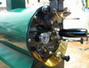
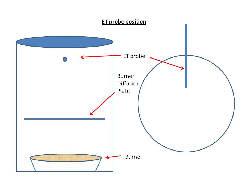
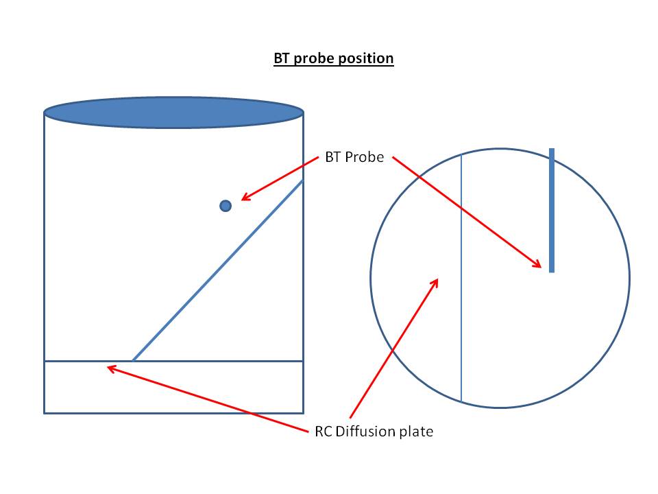
The ET/BT probe positions are as per attached pics
PhilH attached the following images:
|
|
|
|
| greencardigan |
Posted on 10/15/2015 4:51 PM
|
 1 1/2 Pounder  Posts: 1185 Joined: November 21, 2010 |
Looks great! Are you using the TC4 to control the roaster or just logging? |
|
|
|
| PhilH |
Posted on 10/16/2015 5:38 AM
|
|
Newbie Posts: 47 Joined: September 10, 2015 |
Currently just logging and for RoR live readings on Artisan. Control is manual with 0-55psig gas regulator and needle valve for heat and manual speed control of VC. Should I be worried about the high ET temperatures ? |
|
|
|
| joshuatilton |
Posted on 11/11/2015 10:03 AM
|
|
Newbie Posts: 4 Joined: September 08, 2014 |
How did you mount the glass? |
|
|
|
| PhilH |
Posted on 11/29/2015 2:18 PM
|
|
Newbie Posts: 47 Joined: September 10, 2015 |
Hi Josh - apologies for slow reply I cut the square hole in the S/S tubing so that the glass thickness would fit snugly with about 1mm clearance top and bottom but with the width giving about 12mm overlap both sides Then mounted using high temperature sealant (good for about 270C). It comes in red or grey at most hardware stores. To make a neat job I masked the inside and outside of the glass and the edge of the seal line on the S/S pipe. NB - you have to use toughened glass or it will crack. Also make sure the toughened glass is the right size and cut the hole to fit the glass as you cant cut toughened glass (dont ask me how I know this !) Good luck Phil |
|
|
|
| PhilH |
Posted on 11/29/2015 3:47 PM
|
|
Newbie Posts: 47 Joined: September 10, 2015 |
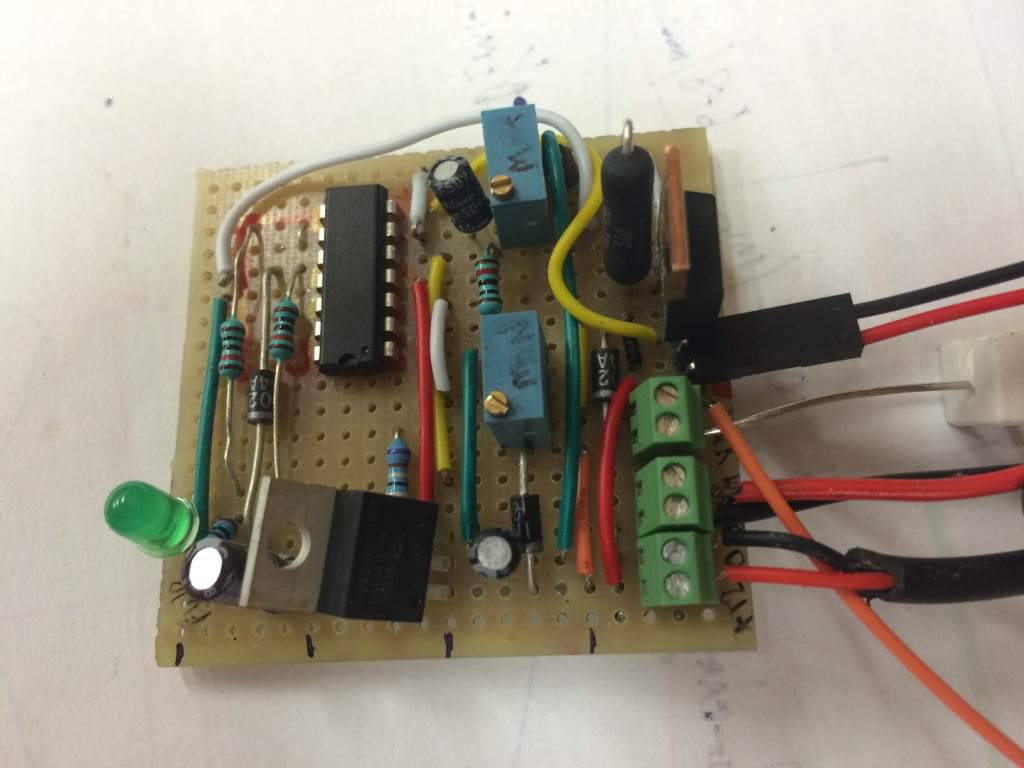
I now have some 20 roasts completed and the results are very encouraging. Great tasting coffee and more consistent results but still manual controls with regulator+needle valve and VC speed control I am trying to implement PID / profile temp control using : - TC4 v6.0 / Arduino R3 UNO / LCDapterC v1.3 / 4x20LCD - Clippard EVP valve (0.025" 0-10V) - Homebuilt EVPD driver board (12V supply, 0-5V DC/2khz PWM) (based on AllenBs kindly supplied propdrivercirc.pdf) link below Proportional Solenoid Valve for Propane http://forum.home...post_54652 This thread has also been very useful TC4 + Clippard EVP Proportional Valve + EVPD Valve Driver http://forum.home...ad_id=4266 Software options I am looking at 1. aArtisanQ_PID / Profile Loader - this has great standalone PID, local loaded Profiles, good 4x20 LCD support, works well with Artisan Scope but doesnt seem to have any easy way to get a PWM output to drive EVPD/EVP valve without extensive software effort. 2. aArtisan 3.10 / Artisan Scope - This has local PID, Artisan Scope based profile support (Artisan sends new ramp SV values to TC4 during roast), PWM16 support including 2.2khz timebase, good support for LCDapter with 2 line LCD but not for 4x20 LCD. Am I correct in my observations above for option 1 and 2 ? I am leaning to option 2, as Option 1 may just be too difficult for me to attempt at this stage Option 2 aArtisan 3.1 Progress So far - Driver circuit (not pretty but works a treat) with min max adjustment pots for output current giving me around 40ma at 0.5V in thru to around 180mA at 4.8V thru a 54 ohm load. EVP valve is due to arrive this week. (photo attached) - I have set PWM to 2.2khz and using serial monitor I can get a good quasi 0-5VDC output from IO3 pin using commands" IO3,nnn" but not from OT1 the PID currently uses OT1 as default output. Questions a) Is it better to use IO3 or OT1 for 2khz PWM output ? b) What is the easiest way to redirect the PID output to IO3 ? in aArtisa.ino in the PID calculations section there is a line reading "levelOT1=Output;" if I change that to "levelIO3=Output" will that do the trick or are there other changes reqd ? Thanks in advance for suggestions / help Phil
PhilH attached the following image:
|
|
|
|
| greencardigan |
Posted on 11/29/2015 9:11 PM
|
|
1 1/2 Pounder Posts: 1185 Joined: November 21, 2010 |
Hi Phil, Quote Am I correct in my observations above for option 1 and 2 ? I think so. It's been a while since I looked at the TC4 sketches. 1. I think modifying aArtisanQ_PID to output a PWM signal wouldn't be a huge task if you were familiar with coding and the arduino system. Currently this sketch uses IO3 for the zero-cross detector input for the phase angle control. So the PWM would have to be set to output on another pin (possibly OT1 or a pwm capable pin not being used by the TC4 shield). The command to set the IO3 PWM is currently disabled in the code but it's still in there and could be re-enabled if needed. 2. For aArtisan, I would definitely try changing the "levelOT1=Output" to "levelIO3=Output". If that doesn't make the PID adjust the IO3 pwm then you might need to add the following code after the LevelIO3=Output. Code Download source float pow = 2.55 * levelIO3; It's possible something like this would also work in aArtisanQ_PID. I'd just create a copy of the sketches and try fiddling the code. |
|
|
|
| PhilH |
Posted on 11/30/2015 9:19 PM
|
|
Newbie Posts: 47 Joined: September 10, 2015 |
Thanks Brad The Artisan0.9.7/aArtisan 3.10 option is now working with PWM on IO3 giving me a nice faux 0-5V output with levelIO3=Output float pow = 2.55 * levelIO3; analogWrite( IO3, round( pow ) ); I'll let you know how I get on with trying to get a PWM output with aArtisanQ_PID (It may take a little longer given my clumsy coding skills) rgds Phil |
|
|
|
| PhilH |
Posted on 12/01/2015 7:02 PM
|
|
Newbie Posts: 47 Joined: September 10, 2015 |
Hi all, I have "fiddled" with Brads aArtisanQ_PID sketch and now have 2.2khz PWM output from PID on IO3. I have just tested with my homebuilt valve driver and it works ! using a 56ohm resistive load io3,0 returns 30mA io3,25 returns 67mA io3,50 returns 105mA io3,100 returns 180mA Now just need to wait for delivery of Clippard EVP valve and I can start roasting with some PID temp control and stored temp profiles, Thanks for all the help and encouragement regds Phil |
|
|
|
| greencardigan |
Posted on 12/01/2015 8:28 PM
|
|
1 1/2 Pounder Posts: 1185 Joined: November 21, 2010 |
Great! Glad you got it working. Could you share the changes you made? maybe upload the files you changed? I was wondering if there would be any conflict using IO3 for the PWM output when it's getting used for the zero-cross input for the phase angle control. Are you using the TC4 to control your blower speed? |
|
|
|
| allenb |
Posted on 12/01/2015 9:54 PM
|
|
Administrator Posts: 3861 Joined: February 23, 2010 |
I'm also curious about the questions Brad posted above. I'm stoked that the Clippard proportional driver circuit you built from works without having to do major tweaks to it. I think you're the first to build this one. What was the cost of components? When you get to dialing things in, remember that along with the settings on your driver board (R3 and R7), you'll need to find the sweet spot with gas pressure to allow a full throttling range of your valve. Too much pressure and you will go from low fire to blast furnace in just a few milliamps change to the valve. Too low of a pressure and you won't achieve sufficient high fire flow when the TC4 is asking for max output. If this circuit is the same as what they use for their retail board then the two pots should be for min and max firing rate. Have you figured out if this is the case and if yes, which pot is which? Keep us posted! Allen Edited by allenb on 12/01/2015 10:06 PM 1/2 lb and 1 lb drum, Siemens Sirocco fluidbed, presspot, chemex, cajun biggin brewer from the backwoods of Louisiana
|
|
|
|
| PhilH |
Posted on 12/14/2015 4:43 AM
|
|
Newbie Posts: 47 Joined: September 10, 2015 |
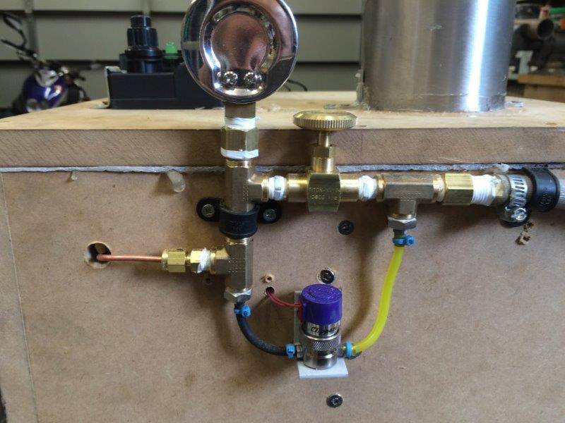
Hi Guys Greencardigan Wrote Great! Glad you got it working. Could you share the changes you made? maybe upload the files you changed? I was wondering if there would be any conflict using IO3 for the PWM output when it's getting used for the zero-cross input for the phase angle control. Are you using the TC4 to control your blower speed? I will upload the files although my arduino skills are rough and quality of coding probably wont impress. :) I commented out or removed a lot of code (which wasnt relevant to my setup) where I thought there would be conflict I havent yet got aArtisanQ_PID operating properly - works locally with local PID and Local Profiles but still not responding properly to Artisan "Read" commands I have added a POT analog input which controls output to valve when PID is in "Manual" mode I have got aArtisan going really nicely now though with Artisan 0.9 with Artisan sending Ramp/Soak SV values to TC4 Still needs more testing No Im not using TC4 for blower speed - I found a 5kW triac based dimmer/motor controller with 0-100 display and up/down buttons on trademe reasonably priced which Im using instead independent of TC4 AllenB wrote When you get to dialing things in, remember that along with the settings on your driver board (R3 and R7), you'll need to find the sweet spot with gas pressure to allow a full throttling range of your valve. Too much pressure and you will go from low fire to blast furnace in just a few milliamps change to the valve. Too low of a pressure and you won't achieve sufficient high fire flow when the TC4 is asking for max output. If this circuit is the same as what they use for their retail board then the two pots should be for min and max firing rate. Have you figured out if this is the case and if yes, which pot is which? R3 is "zero" or minimum output current R7 is "range" or max output current I have connected all the hardware with 1/8 copper tubing and a 2 bar pressure gauge downstream of the Clippard and the manual bypass needle valve (see pics) and I added a continuous spark electronic igniter button (powered by AAA battery which is much better than clackety clack one I had previously. I have been dialing it in and adjusting minimum setting for the smallest safe stable flame and maximum at around 180ma which is the rated full open setting of the clippard EVP The output pressure on the gauge does hunt a bit with the hysteresis but not too bad Still working on the PID tuning and getting a bit of overshoot on the recovery after "DROP"but then tracks within a degree or so ( see attached Artisan graph) I have also built a loading hopper and a simple "plug" which I lift to load beans and a drop chute based on Tamarians which drops into a bucket/colander which is using the suction from the main VC for cooling |
|
|
|
| PhilH |
Posted on 12/14/2015 4:51 AM
|
|
Newbie Posts: 47 Joined: September 10, 2015 |
trouble with attachments - I'll try again
PhilH attached the following images:
|
|
|
|
| greencardigan |
Posted on 12/14/2015 4:55 AM
|
|
1 1/2 Pounder Posts: 1185 Joined: November 21, 2010 |
Maybe try debugging with the arduino serial terminal. Send the read command from there and see what data is returned. Also, check what mode you have set in user.h. There's Artisan, Roastlogger, Android or comment them all out for stand alone mode. |
|
|
|
| PhilH |
Posted on 12/14/2015 5:11 AM
|
|
Newbie Posts: 47 Joined: September 10, 2015 |
modified arduino sketches and component list attached below (hopefully)
PhilH attached the following files:
|
|
|
|
| PhilH |
Posted on 12/14/2015 5:18 AM
|
|
Newbie Posts: 47 Joined: September 10, 2015 |
Clippard Valve and Valve Driver (Attached hopefully)
PhilH attached the following images:

|
|
|
|
| PhilH |
Posted on 12/14/2015 5:20 AM
|
|
Newbie Posts: 47 Joined: September 10, 2015 |
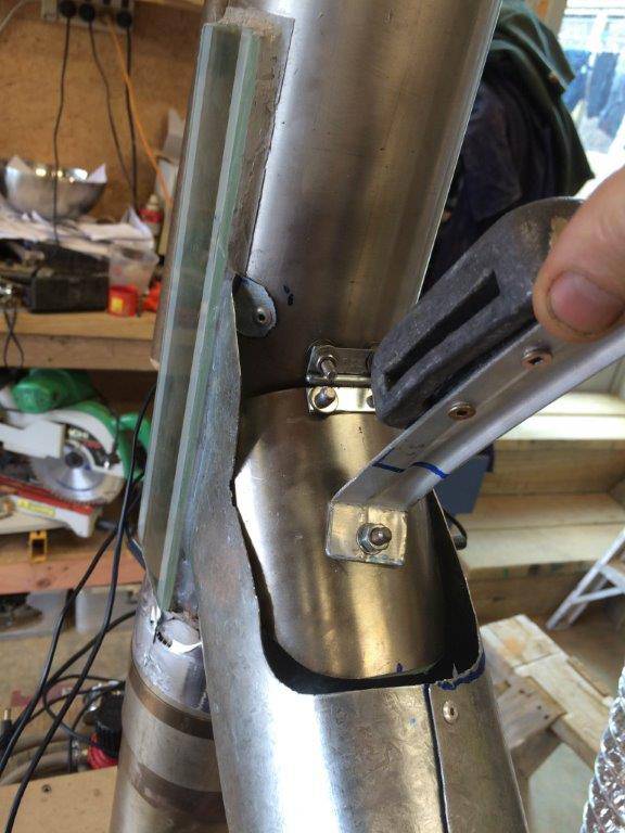
drop chute detail (attached) only seem to be able to attach 2 files max ??
PhilH attached the following images:


|
|
|
|
| PhilH |
Posted on 12/14/2015 5:21 AM
|
|
Newbie Posts: 47 Joined: September 10, 2015 |
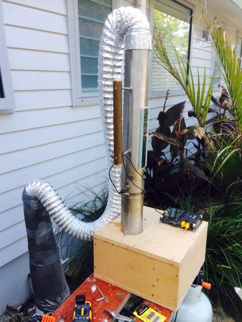
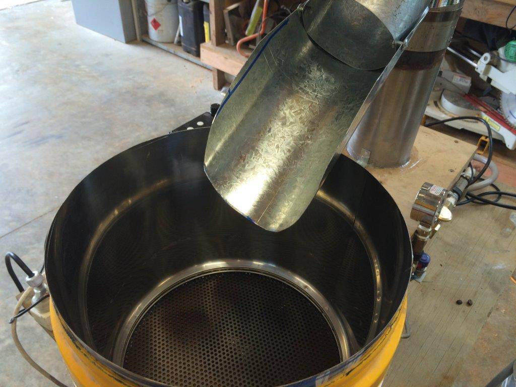
roaster and loading hopper c/w bung for loading
PhilH attached the following images:


|
|
|
|
| PhilH |
Posted on 12/14/2015 5:26 AM
|
|
Newbie Posts: 47 Joined: September 10, 2015 |
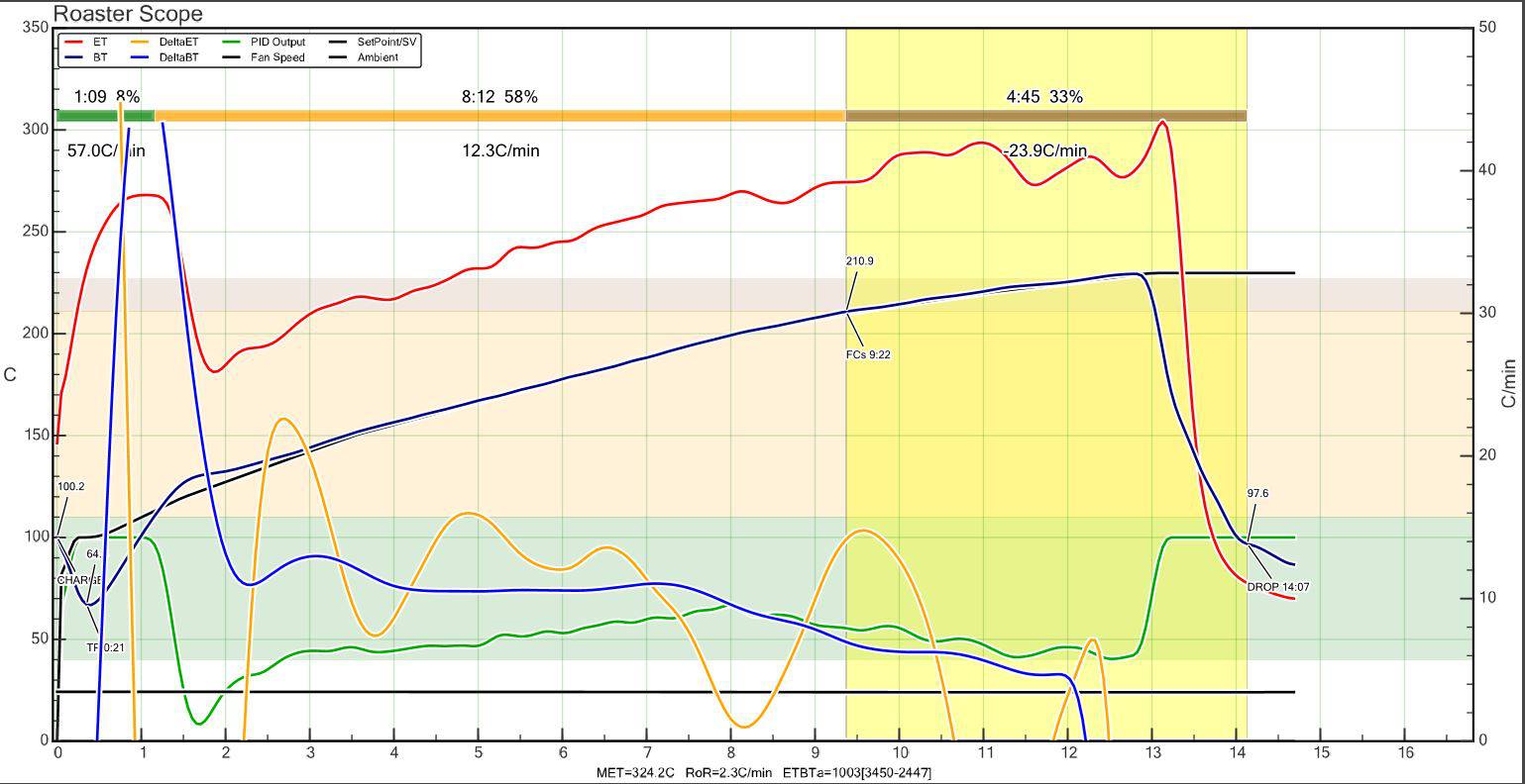
todays roast graph from Artisan Scope - small overshoot after recovery from Drop but pretty much follow the profile very closely within a degree or so having real trouble with attachments - Ill try a zip file of graph ADMIN Edit: PDF extension not supported file type. Converted to jpg and attached. . .
PhilH attached the following file:
PhilH attached the following image:
Edited by JackH on 12/14/2015 6:06 AM |
|
|
|
| greencardigan |
Posted on 12/14/2015 7:07 PM
|
|
1 1/2 Pounder Posts: 1185 Joined: November 21, 2010 |
Quote I saved a diffchecker result to view your changes. They all look fine. See here https://www.diffc...m/un2ho7qw |
|
|
|
| allenb |
Posted on 12/14/2015 8:07 PM
|
|
Administrator Posts: 3861 Joined: February 23, 2010 |
Quote PhilH wrote: todays roast graph from Artisan Scope - small overshoot after recovery from Drop but pretty much follow the profile very closely within a degree or so Your making excellent progress with this roaster! I'm quite impressed at how well the burner control is working out and how tightly it's controlling. This tells me your PID settings are very close to right on the money. Let is know how well the fill and dump mechanisms work and if you had any challenges getting them to behave. Once you've got everything to your liking, shoot us a video of the fill and dump in action. Allen 1/2 lb and 1 lb drum, Siemens Sirocco fluidbed, presspot, chemex, cajun biggin brewer from the backwoods of Louisiana
|
|
|
|

Page 1 of 2: 12
| Jump to Forum: |
Powered by PHP-Fusion Copyright © 2024 PHP-Fusion Inc
Released as free software without warranties under GNU Affero GPL v3
Designed with ♥ by NetriXHosted by skpacman