
Login

Shoutbox
You must login to post a message.
renatoa
05/18/2024 4:18 AM
Tech2C, 
renatoa
05/17/2024 11:29 AM
 jhondue
renatoa
05/16/2024 2:02 AM
Dbic and buddy_magi,
 ?
?
?allenb
05/15/2024 5:30 PM
buorus

renatoa
05/14/2024 7:01 AM
 , kazozero
Forum Threads
Newest Threads
Skywalker, the ALM c...New to roasting. Co...
Skywalker Roasts
Roasting Peru Washed
Skywalker bearing ch...
Hottest Threads
| Skywalker roaster... | [320] |
| Skywalker, the AL... | [242] |
| Skywalker Roasts | [97] |
| War on Farmers by... | [41] |
| New to roasting. ... | [31] |
In Memory Of Ginny

Donations
Latest Donations
dmccallum - 10.00
JackH - 25.00
snwcmpr - 10.00
Anonymous - 2.00
Anonymous - 5.00
dmccallum - 10.00
JackH - 25.00
snwcmpr - 10.00
Anonymous - 2.00
Anonymous - 5.00
Users Online
Guests Online: 2
Members Online: 1
allenb
Total Members: 8,269
Newest Member: Tech2C
Members Online: 1
allenb
Total Members: 8,269
Newest Member: Tech2C
View Thread
Who is here? 1 guest(s)
Page 1 of 2: 12
|
 1kg (or 2 lb) fluidbed build with TC4 and automation
|
|
| ETomczak |
Posted on 05/06/2023 11:12 AM
|
|
Newbie  Posts: 39 Joined: February 06, 2023 |
Hi all, I was part of this forum about 9 years ago under the username Erichimedes, but that account isn't working for me for some reason, so I've started another to participate again. I've been roasting for about 10 years, started with a popper, then modified the popper, then build a roaster from scratch, then that roaster was modified, and now I'm building what I hope to be a roaster I can really go for many more years with. The goals were: -Ability to roast 1kg, or at least 2lbs. -Relatively compact footprint -Flexible, with all parts being easily replaceable -True safetys in place, so that unexpected errors can't result in burning out an element or starting a fire -Easy to use -Roast logging via TC4 -Full manual operation available from the control panel and, -Full automatic operation available via communication with Artisan on a laptop I'm a metal fabricator by trade and my shop is at my house, so I have plenty of tools at my disposal. The tools I have available, and the materials I can find generally inform my design decisions. I started building about 2 months ago, and the roaster is functional now. I made the first roast chamber too narrow, so it only roasts about 1.25lb without chuffing. The chuffing isn't a huge deal, but it bugs me, so I'm working on a larger diameter chamber now. The next post will be for pictures I took during building, then I'll continue to update as I get the final wrinkles ironed out. I'm having trouble setting the correct PID parameters in Artisan so that it follows a profile well, so I'd love some input on that if anyone has some knowledge for me. Edited to add: a photo of the roaster as it sits right now. It works! It just needs some of the kinks worked out, and a new roast chamber for larger batches. 
Edited by ETomczak on 05/06/2023 3:13 PM |
|
|
|
| ETomczak |
Posted on 05/06/2023 11:31 AM
|
|
Newbie Posts: 39 Joined: February 06, 2023 |
I started with the core of the roaster, the blower and heating element assembly. I had a few things laser cut from stainless to help with the fabrication. I used a stainless pot as a stainless tube, since it was the same diameter as the vacuum cleaner motor I had selected for this project. Then a laser cut plate went from the pot to two 2" diameter stainless tubes (dairy pipe) and then I made a junction to go from those two to a single 2" tube at a right angle. That was made from 3" dairy pipe, and the end caps were laser cut. I also had some feet laser cut, and those just needed to be bent at a right angle, then the bolted on to the whole assembly.  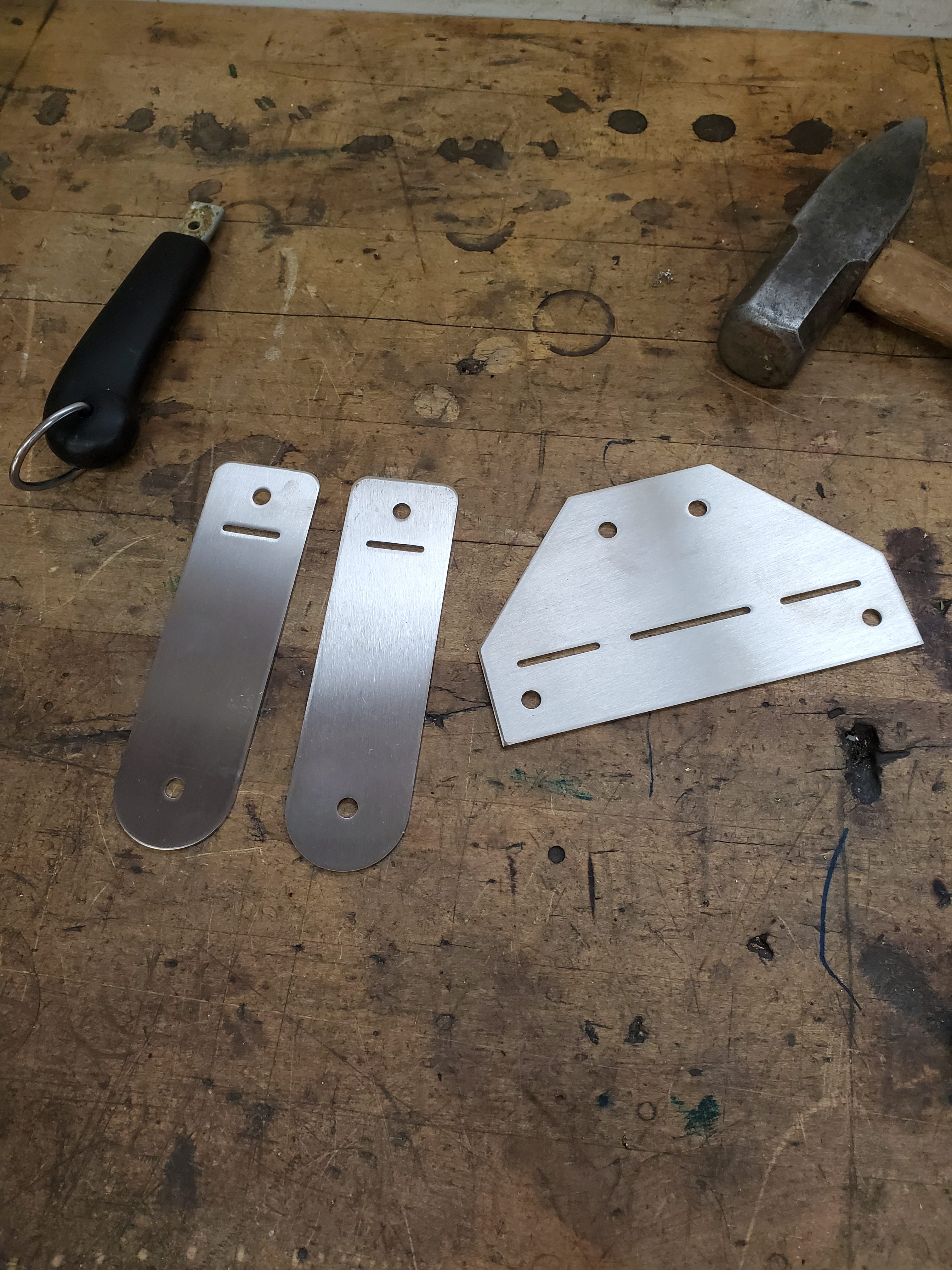 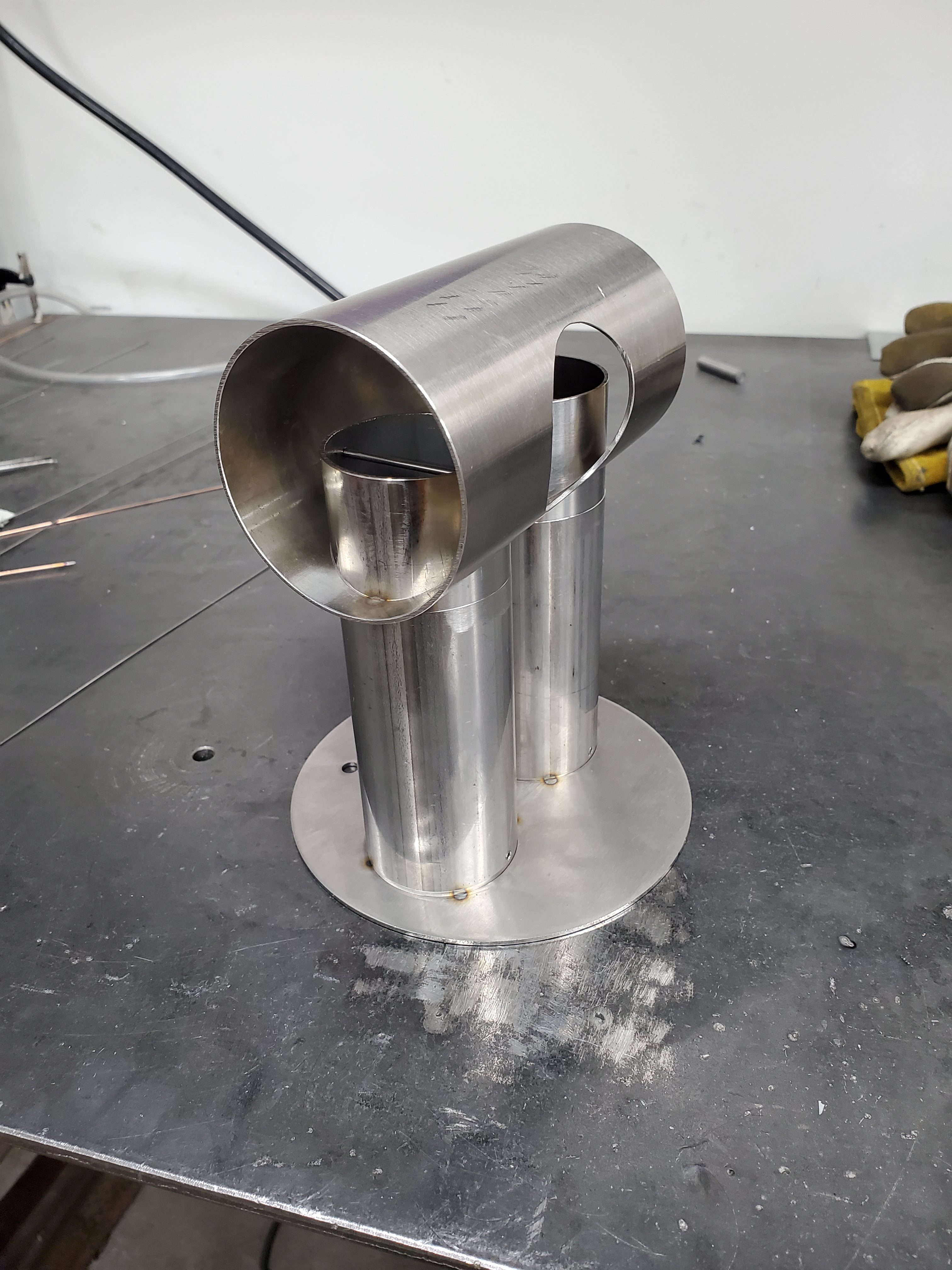  Here's the vacuum cleaner motor attached via a 5" rubber DWV coupler. The final vertical 2" tube is missing, I welded that in last. 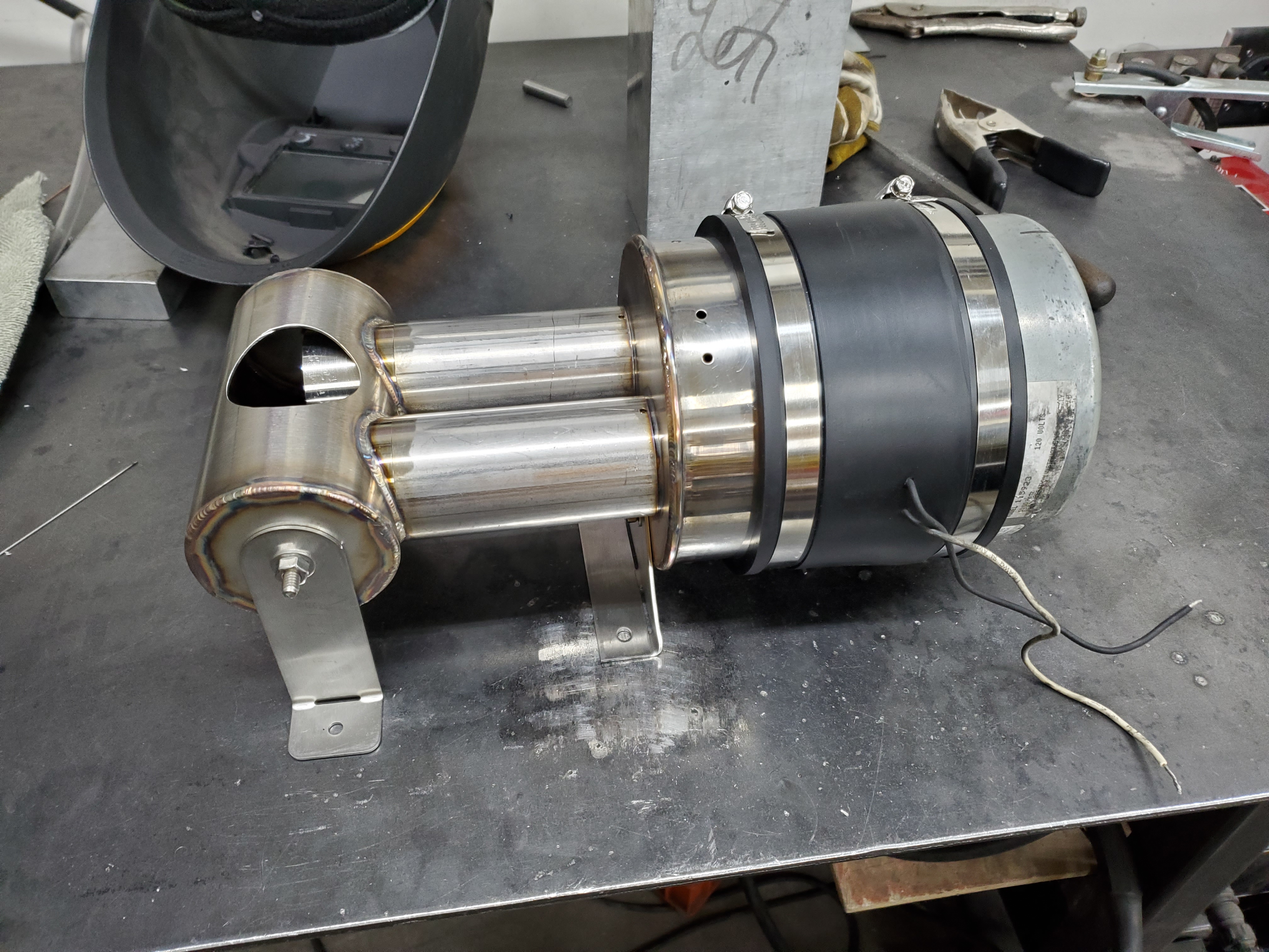 This worked out well, and I'm pretty happy with it. The motor and the heating elements are both easily replaceable, and it's very symmetrical, so I'm fairly confident that there is close to equal amounts of air flowing through both elements. Each element is a Master Appliance AH752. I had to grind down the mica just a little for it to fit in the 2" tubing, but overall it's a nice fit and the elements are held in place by wires that fit the slots in the mica. We run at about 246 volts where I live, so I should have about 4400w on tap, which I think is enough to roast 1kg if the chamber is well designed.  Next post will be about the roast chamber! Edited by ETomczak on 05/06/2023 2:34 PM |
|
|
|
| CK |
Posted on 05/06/2023 2:11 PM
|
|
1/2 Pounder  Posts: 252 Joined: December 07, 2018 |
I used to roast with BT PID, which worked but was not so great. Then I changed to ET PID which was much easier to dial in and provided for a highly controllable roasting environment throughout the roast. For over a year now, I've abandoned PID control in favor of roasting using power profiles that change with time-based alarms adjusting power directly from Artisan. This provides an easy platform to create a roast environment that is 100% predictable based on the thermal characteristics of your machine's roast chamber. Interestingly, the values in the image from the below post work for ET PID on the transparent roaster and the roaster908... hot air inlets with the same 5mm thermocouples responded the same. This post shows the PID settings in Artisan for the ET PID of the hot inlet air... #102 and #104 on this page; https://homeroast...wstart=100 |
|
|
|
| ETomczak |
Posted on 05/06/2023 3:10 PM
|
|
Newbie Posts: 39 Joined: February 06, 2023 |
Here's a quick post about the roast chamber that I'm unhappy with. I definitely should have tested it before putting in all the work, but oh well. The base where the taper is started life as a stainless steel martini glass. This is my new favorite source of tapered stainless shapes, since they can be had on ebay for pretty cheap. Just cut to suit.  I bored the stainless tube I was using out a bit to thin the walls down. Doing this in stainless was a massive pain in the butt.  Then used the lathe to line the taper up with the 2" stainless for the bottom while I tacked it. 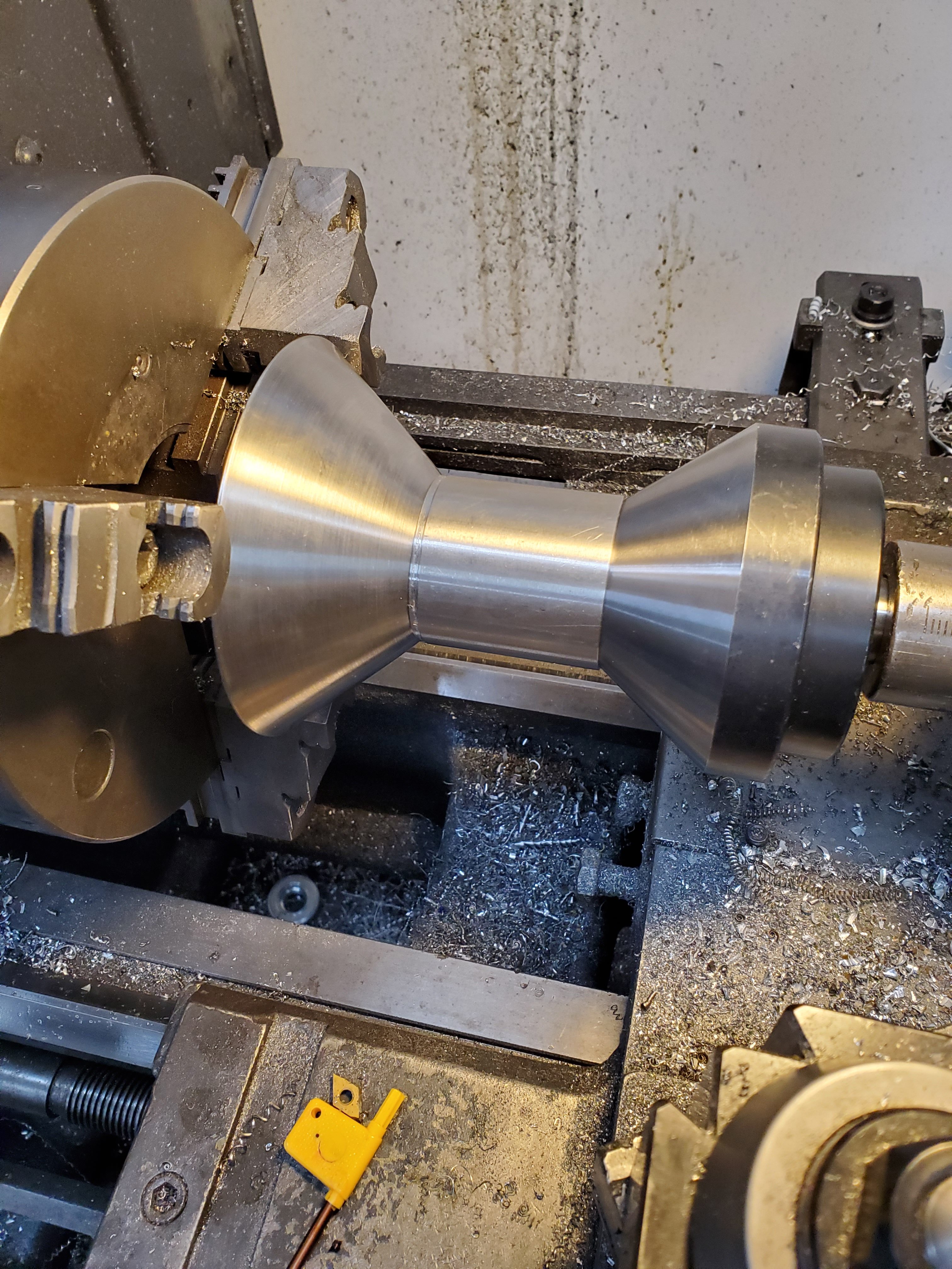 Ready for welding.  I don't have photos of the top section, that goes above the glass tube, but it was simple. Then I needed a wood handle, which I didn't have access to, so I turned one from a piece of local Juniper!   Here is more or less the finished product.  And unfortunately, the beans don't circulate too well. The original inlet hole diameter was 1.625", but I made a small plate that reduces that down to 1.375 and that improved things a lot. I tried two different types of perforated plate to see if that made a difference, one with big holes and one with small. No difference at all between the two. I think I'm going to try another plate that reduces the inlet hole down to 1.25" and see how that does. It definitely won't work for 1kg, but I'm going to aim for good performance with 1.5 lbs and that will make me happy enough. The blower I'm using is at like 20% capacity to loft the beans, so power is not a problem at all. I think the narrower hole could help blow through the tall skinny bean pile without wandering or chuffing so much. But I will experiment and see. I'm also going to be working on another roast chamber. I currently have materials that could make one that is 5.375" inside diameter. I'm curious if anyone here has experience with a chamber of roughly that size? I'd like if it could roast 1kg, but also as little as a pound. Although I'm less inclined to have it work for smaller batches now that I have this other chamber to use for that. |
|
|
|
| ETomczak |
Posted on 05/06/2023 3:25 PM
|
|
Newbie Posts: 39 Joined: February 06, 2023 |
Quote CK wrote: I used to roast with BT PID, which worked but was not so great. Then I changed to ET PID which was much easier to dial in and provided for a highly controllable roasting environment throughout the roast. For over a year now, I've abandoned PID control in favor of roasting using power profiles that change with time-based alarms adjusting power directly from Artisan. This provides an easy platform to create a roast environment that is 100% predictable based on the thermal characteristics of your machine's roast chamber. Interestingly, the values in the image from the below post work for ET PID on the transparent roaster and the roaster908... hot air inlets with the same 5mm thermocouples responded the same. This post shows the PID settings in Artisan for the ET PID of the hot inlet air... #102 and #104 on this page; https://homeroast...wstart=100 Hi CK, thanks for chiming in. I've seen your builds with some interest, very cool stuff! Interesting, maybe this is the route I'll end up going. I think in my case I would want to set temperature-based alarms instead, but I think Artisan does that too. Originally I was excited for PID control because I wanted to be able to roast one or two lbs, in the same roast chamber, to the same profile, and get the same result. But I'm realizing that maybe the PID settings are so sensitive to changes in the roast chamber that even doing different batch sizes is going to require different PID settings, which is a pain. I'd also like to be able to do roasts back to back without preheating the RC for the same reason, but again, maybe this just isn't in the cards. I'm going to keep messing with it and see what I can do. I'm hoping someone who uses PID off of BT with their roaster chimes in with some settings that worked for them, just so I can have a baseline to start from. Right now it overshoots by like 80 degrees before even turning the heat down from 100%, then doesn't even get close to the SV before going back to 100%, it's just all over the place. |
|
|
|
| CK |
Posted on 05/06/2023 5:47 PM
|
|
1/2 Pounder Posts: 252 Joined: December 07, 2018 |
Quote The original inlet hole diameter was 1.625", but I made a small plate that reduces that down to 1.375 and that improved things a lot... I think I'm going to try another plate that reduces the inlet hole down to 1.25" and see how that does... I think the narrower hole could help blow through the tall skinny bean pile without wandering or chuffing so much. The transparent roaster inlet size (not including perforated plate or mesh restrictions) represented about 23% of the roast chamber inner diameter... no chuffing with any batch size. Maybe that ratio will work well with your various RC sizes. Nicely built machine. |
|
|
|
| ETomczak |
Posted on 05/07/2023 5:47 PM
|
|
Newbie Posts: 39 Joined: February 06, 2023 |
Interesting about the 23%. I have seen in other places on this forum where folks tend to get better results from larger inlet holes, but my experience has been the other way around. My last roaster's inlet hole area was 13% of the overall roast chamber cross sectional area, and that worked really well. That neighborhood is what I'm having decent luck with on this roast chamber too. Back when I had a smaller roast chamber made from a bake-a-round tube, I had a much larger percentage inlet hole, and that seemed to work ok, but those percentages haven't seemed to scale up well. I think one piece of the puzzle here is: when your roaster has a full charge of green beans, is the bean mass wider than it is tall, or the other way around? or is it about equal? The problem with this roast chamber is that even with a smaller 1.5lb charge, the bean mass is about 1.5 times taller than it is wide, so as soon as the beans start expanding, I've got problems. By the way, I did a roast yesterday using alarms in Artisan, and I really like that method! I still want to try and figure out using the PID function, but the alarms method is a pretty cool way to get repeatable results, and it's easy to modify to try and get what I want from the roaster. I used temperature alarms, but I can see time ones working well too. In general, that's a neat feature in Artisan, thanks for pointing me towards it. |
|
|
|
| CK |
Posted on 05/10/2023 10:27 AM
|
|
1/2 Pounder Posts: 252 Joined: December 07, 2018 |
Although I ran up to 325g in the transparent roaster, my normal batch size was 275g green, and that yielded an almost equal bean height in the chamber when compared to its inner diameter. (ie. 86mm ID and near 90mm bean height, and @ 325g batch the green bean height was closer to 100mm) Maybe that’s why the 23% worked so well in my case. In any event, the transparent roaster is now decommissioned and its parts were divided up for other projects. |
|
|
|
| greencardigan |
Posted on 05/10/2023 6:53 PM
|
 1 1/2 Pounder  Posts: 1185 Joined: November 21, 2010 |
Quote ETomczak wrote: I'm hoping someone who uses PID off of BT with their roaster chimes in with some settings that worked for them, just so I can have a baseline to start from. Right now it overshoots by like 80 degrees before even turning the heat down from 100%, then doesn't even get close to the SV before going back to 100%, it's just all over the place. In my 1kg roaster I use Source BT Proportional on error mode kp: 4.00 ki: 0.03 kd: 0 For my 250g roaster Source BT Proportional on error mode kp: 0.8 ki: 0.05 kd: 0 My 1kg roaster follows the profile much better than my 250g roaster. Although it's definitely not perfect. I get a small overshoot and some minor oscillation, mostly before first crack. I haven't really tried getting it better is I'm lazy and it's working ok how it is. I may also try using ET as the source sometime too. You could try proportional on input mode. Supposedly that shouldn't overshoot, but I haven't tested. And I like your build.  I used a stainless steel martini glass in my 250 gram roaster too. I used a stainless steel martini glass in my 250 gram roaster too. |
|
|
|
| HarryDog |
Posted on 05/10/2023 8:25 PM
|
 1/2 Pounder Posts: 346 Joined: July 20, 2022 |
For PID settings, I have not done this yet but liked Jason Scotts settings. Source BT kp=3 ki=0 kd=45 Lookahead=0s Set Start PID on charge He lets the curve catch up during the drying phase. |
|
|
|
| renatoa |
Posted on 05/11/2023 2:05 AM
|
|
Administrator Posts: 3045 Joined: September 30, 2016 |
I don't understand the above kd value, I can't justify it in any realistic scenario. Unless the sample time is very high, about 15 seconds. Logically, the maximum kd value should be set to compensate the kp action of a sudden bump/crash (error) that happens during a single sampling interval. For the typical one second sampling interval kD should not be bigger than kP. In my TO machine I am using settings close to @greencardigan 250g machine, with the only significant difference that kD is equal to kP. I can explain the reasoning behind the values. |
|
|
|
| HarryDog |
Posted on 05/11/2023 7:59 AM
|
|
1/2 Pounder Posts: 346 Joined: July 20, 2022 |
His explanation is no undulations, it takes 2.5 minutes to lock on (Slow Ramp) and other examples I saw undulate (Overshoot & Undershoot) as it attempts to lock on to the background profile. So maybe more personal preference then can you taste any difference. |
|
|
|
| renatoa |
Posted on 05/11/2023 10:32 AM
|
|
Administrator Posts: 3045 Joined: September 30, 2016 |
A strong derivative factor means noise amplification in control theory... I don't see what could damp undulations... conversely... If you have a temperature change of 0.1 degree from a second to the next, which is the resolution of typical measurement device, and equates to 6C/min RoR, this kD term will produce a change of 4.5% in heater output, which is a lot ! His heater control should look jagged as a saw... Noticed he is using a servomechanism to control heater, probably gas vane... completely other dynamics than a fluid bed control. You don't drive a Corvette as a Diesel van... |
|
|
|
| HarryDog |
Posted on 05/11/2023 12:59 PM
|
|
1/2 Pounder Posts: 346 Joined: July 20, 2022 |
The roaster is a Artisan 6 (FB), looks to be electric. No natural gas or propane in the manual. The heater is represented with the yellow line the adjustment of the servo, not exactly smooth but not saw-tooth either. Well I'm only short a couple of parts to convert my little FB to Artisan control it might be time to order them up and do some testing! |
|
|
|
| ETomczak |
Posted on 05/14/2023 4:34 PM
|
|
Newbie Posts: 39 Joined: February 06, 2023 |
greencardigan, Thanks so much for those values, I will give them a try when I do my next roast. I need a decent profile to follow, so I've been getting to know my roaster with manual input and learning it's ups and downs (literally) and saving any profiles that come out well. And thanks for the nice words. I've enjoyed looking at your builds over the years as well. The martini glasses are fantastic. I have more on the way for a new roast chamber. I've decided on going with a 5.7" id chamber for 1kg (and/or 2lbs) which should also work reasonably well for 1lb. HarryDog: That looks like an interesting video, I'll check it out when I have a few minutes of free time. Even if the values he uses wont work for me, the explanation will no doubt be really helpful. Renatoa: Thanks for your input as well, I'll try some values on my roaster and hopefully be able to get it dialed in well. As for build progress: I will post some pictures of the base unit soon. It is finally complete, the last step was adding sound insulation around the VC motor, and installing an air pressure safety on the control input of the heater relay. So now, if the blower shuts off for any reason at all, the heaters won't turn on. It seems the closest to fail safe that I can get for preserving the heater coils. The unit I used was not only really nice, and fully adjustable, but it was affordable too: https://www.suppl...e-1-10-W-C |
|
|
|
| renatoa |
Posted on 05/15/2023 1:48 AM
|
|
Administrator Posts: 3045 Joined: September 30, 2016 |
Sent you a PM with an alternative, not sure if reached your inbox. |
|
|
|
| ETomczak |
Posted on 05/18/2023 9:19 AM
|
|
Newbie Posts: 39 Joined: February 06, 2023 |
Renatoa, I did get your message, I have responded. Thanks for the info! |
|
|
|
| ETomczak |
Posted on 05/23/2023 3:28 PM
|
|
Newbie Posts: 39 Joined: February 06, 2023 |
Ok, so here is the main box, the guts of the roaster. I tried to design it with as much flexibility in mind, and all of the components are easy to replace, industrial grade components that should last a really long time. I wouldn't have put that much stock in the quality of components early on in my roasting, but the first roaster I built from scratch roasted for 10 years straight. I'm hoping this one goes for even longer, and I'm hoping to start roasting for my friends too, so it will be doing more batches. Here is the main panel. All controls are on top. The roast chamber is just a slip fit of 2" sanitary stainless tube, so I can make new roast chambers and they will just slip right into the main heat/air outlet easily. The thermocouple is connected by a plug, so I can easily remove and dump the beans into the cooler, which is on the upper right. The cooler is just the air intake of the whole roaster, so I turn up the main blower and cool the roast chamber and the beans at the same time. The pot slips out and the beans can be dumped into a storage container. The TC4 screen is my main source of temp readings, of course. I designed the first roast chamber with an analog thermometer as well, but I'm going to forgo that in the future. I thought it looked cool, but I'm just not using it at all with an accurate thermocouple set up. Bottom left are the main power buttons, black is on, red is off. They trip a 240v contactor, so that if we lose power or something odd happens, the roaster defaults to "off". The two switches, dials and indicator lamps are for the blower and heat. 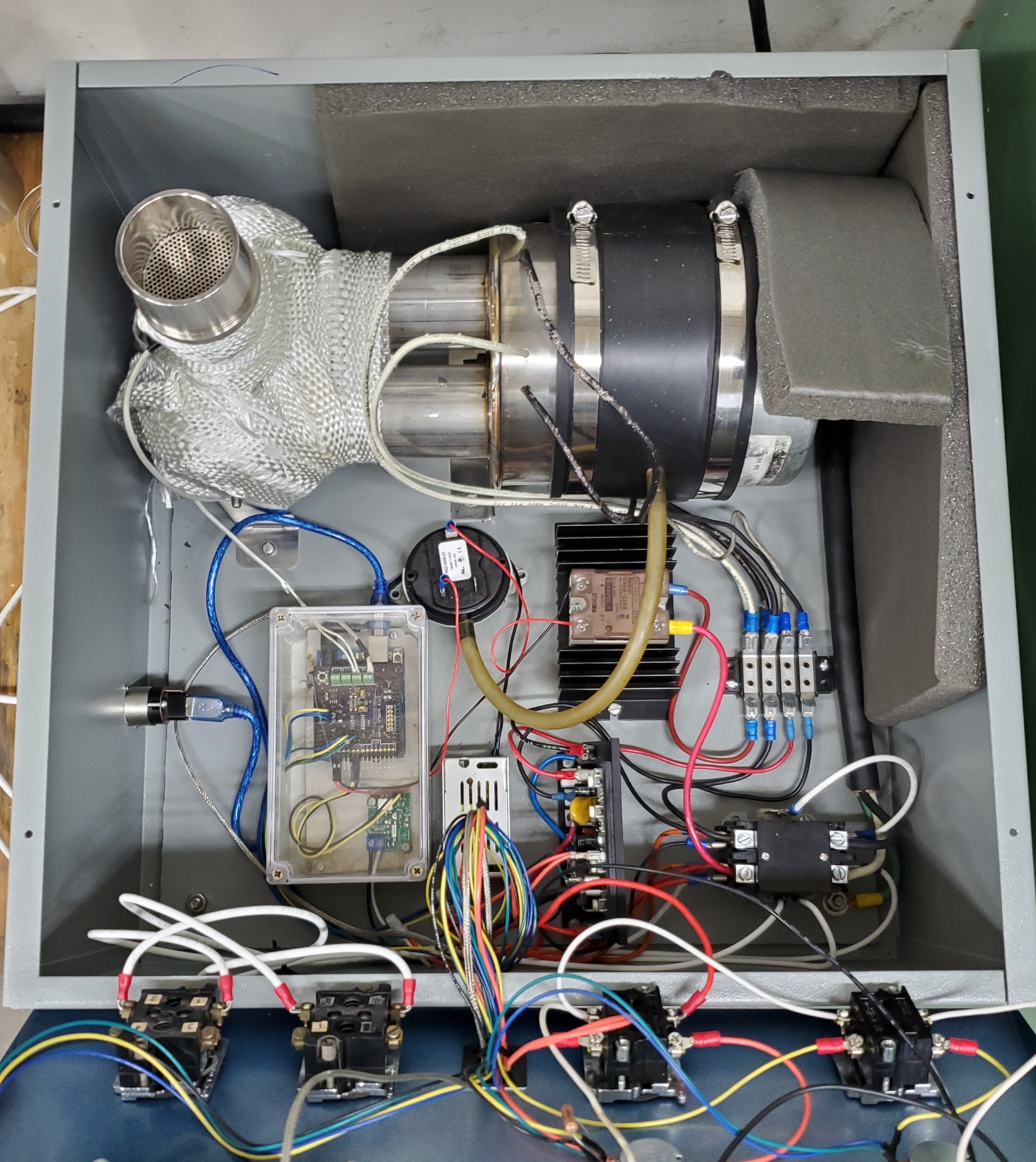 Here's the inside. -At the top you can see the blower/heater assembly installed. There's fiberglass insulation wrapped around the hottest part of the outlet, it helps a lot to keep the housing temp reasonable. -Middle right is the terminal block for the blower/heater assembly. This makes removing that part and working on it much easier. -Bottom right is the main 240v contactor. My favorite part of using this to power the machine is that it goes "clunk" when you hit the on button :) -Bottom middle is the DC motor control for the blower. It's a KBIC-240DS, so 240v AC in and 90v DC out. -Bottom left is the TC4/Arduino housing. -Middle left you can see the USB socket installed in the wall of the chassis. -Center is the pressure control switch. It senses pressure from the blower, and then will close the control circuit from the TC4 to the main heat SSR. No air: no heat. I'm pretty pleased with this unit as it is. The only thing I might change is the blower control. Now that I'm doing a deep dive into Artisan and using it for every roast, I'm kind of wishing I could integrate blower control into the automation. I would either have to figure out if my 120v blower would work with 240v and phase angle control, or I'd need to find a replacement blower that is natively 240v. I'd rather not spend more money on a new motor, so maybe this is a ways out. Anyway, that's mostly it. The new glass tube for my new 6" roast chamber arrived yesterday, so I'll start building that here soon and then test it out with a 1kg roast. The funny thing is that with all this new energy into roasting, I'm all fired up to try a lot of different beans again, so I'm really just in need of a 1/2 lb roast chamber! I just need to get some friends on board, and I can sell the extra beans to them. |
|
|
|
| ETomczak |
Posted on 06/20/2023 8:27 AM
|
|
Newbie Posts: 39 Joined: February 06, 2023 |
I'm putting the final touches on my 6" (150mm actually) roast chamber, and I feel much much better about the size and bean circulation with this one. I will post pictures soon. I saw a good deal on a 240v blower on ebay, so I snagged it and figured I would set up PAC through the TC4. I also picked up an instantaneous turn-on SSR, and have installed all of it into the roaster. I'm having a couple issues, maybe folks here could help me. It's possible there is something wrong with the potentiometer I'm using, because I don't have the last 10% or so of blower speed if I turn it all the way to full. It goes to about 87% (as displayed on my LCD) and just tops out. I've also adjusted the range in the user.h file to 10-40% since that's all I need from this blower to do what I want. Now it just tops out at 35%. It is possible this is the source of my next (more concerning) problem, but I don't think so. I'll put a new pot on order anyway. There is one speed that the blower really doesn't like. It is 15%. If the blower is set to that, it twitches and jerks and speeds up and slows down and sounds horrible. It's almost like a resonant frequency, there's something going on with the power output to the motor. Has anyone else run into this? I'm running aArtisanQ_PID 6_8 in CONFIG_PAC3 mode. I have the ZCD hooked up to IO3, although I guess I have no idea if it's even working, I just hooked it up and assumed it to be working correctly. Phase angle control option is set to TRIAC_MOTOR. Just ask if you want to know any of my other settings. I thought maybe the pot was causing the trouble at 15% but the motor twitches more times per second than I believe the TC4 is reading the pot, so I don't think there's a feedback loop issue. I had the same problem when the pot was not installed in the machine and it was outside, so I don't think the high voltage wires are doing anything, but it's possible they are. Thanks in advance for any help! UPDATE: I also tried controlling the roaster from Artisan, and I get the same issue when the blower is set to 15%, twitching, jerking, and blows faster than it should at 15. So this issue isn't stemming from the pot. Edited by ETomczak on 06/20/2023 12:02 PM |
|
|
|
| ETomczak |
Posted on 06/21/2023 11:24 AM
|
|
Newbie Posts: 39 Joined: February 06, 2023 |
I've been investigating this problem non stop, and I have some new questions: I might have my ZCD from Greencardigan hooked up wrong. My roaster is 240v, and I put both hot lines into the ZCD input terminals. Should I have that hooked up differently? Like just one hot leg and then the other to ground? I don't have a neutral line to the roaster, just two hot legs and a ground. On the other side, I don't know if I have the low voltage stuff hooked up right. I'm using IO3 on an old v4.00 TC4, and I have ground to ground, and ZC hooked up to + on the TC4, but nothing on 5v on the ZCD. I read somewhere on this site (can't find it now) that this was how it was supposed to go, but maybe I'm wrong? I don't have indicator lights on top of my TC4 board, so I can't see the flashing referred to elsewhere that shows the ZCD is working correctly. EDITED: To add yet more info. I checked the voltage on OT2 where the SSR is connected. I have the fan limits setup to run from 10 to 50%. From 50 to 16% the voltage is a relatively stable 2.72v, but at 15% (during the unstable running) the voltage varies from 2.7 to 2.6, then from 14 to 10%, the voltage steadily decreases incrementally to something around 2.1 or 2.2, I don't remember exactly, sorry I didn't write it down. But oddly there's something specific happening at 15% where the output of the TC4 changes in some way. I know this may be a useless reading since I don't have an oscilloscope, but I figured it was worth sharing anyway. Edited by ETomczak on 06/21/2023 12:58 PM |
|
|
|
| ETomczak |
Posted on 06/22/2023 11:51 AM
|
|
Newbie Posts: 39 Joined: February 06, 2023 |
A breakthrough! In the user.h file, under Phase Angle Control options, if I enable TRIAC_HEATER instead of TRIAC_MOTOR it works fine at 15%! Every other speed (between 10 and 50%, which is all I tested) works fine too. So my question is, to anyone who knows, can I run the program with the heater option enabled instead of the motor option? Will I hurt anything? Now the only last thing to figure out is why the fan motor randomly turns on for a few seconds sometimes when the machine is on but the fan potentiometer is disabled. I'm assuming a new pot will fix that but we'll see. |
|
|
|
| greencardigan |
Posted on 06/24/2023 5:27 AM
|
|
1 1/2 Pounder Posts: 1185 Joined: November 21, 2010 |
Changing to the triac_heater option shouldn't be a problem. All it does is change the duration of the output pulse. You can find those values or adjust them in the phase_ctrl.h file. There's also an option there to adjust the timing of the ZCD pulse VS the actual zero cross if needed. In your PM you asked what I did to fix the motor pulsing issues I had. If I remember correctly I just needed to connect my TC4 ground to the mains ground. The LED that lights to indicate that AC zero cross pulses are being detected is on the Arduino board, not the TC4 board. Not sure why your fan would randomly come on. When you say the pot is disabled, do you mean you have it disabled using the option in the user.h file? Edited by greencardigan on 06/24/2023 5:32 AM |
|
|
|
| ETomczak |
Posted on 06/25/2023 12:32 PM
|
|
Newbie Posts: 39 Joined: February 06, 2023 |
Quote greencardigan wrote: Changing to the triac_heater option shouldn't be a problem. All it does is change the duration of the output pulse. You can find those values or adjust them in the phase_ctrl.h file. There's also an option there to adjust the timing of the ZCD pulse VS the actual zero cross if needed. In your PM you asked what I did to fix the motor pulsing issues I had. If I remember correctly I just needed to connect my TC4 ground to the mains ground. The LED that lights to indicate that AC zero cross pulses are being detected is on the Arduino board, not the TC4 board. Not sure why your fan would randomly come on. When you say the pot is disabled, do you mean you have it disabled using the option in the user.h file? Thanks so much for your input. Great to know about the triac_heater option, I'm so glad that fixed it. Great to know about grounding the TC4. Interesting, I did try that as well with no effect. Odd about the LED. I hope it's all working right. It's possible I didn't have the fan blowing when I checked the LED, maybe that would make a difference. I did unplug the ZCD then try to run the fan and it didn't work, I assumed that to mean the ZCD was working. Have now fixed the fan randomly coming on issue. Originally, I had the fan pot wired so that the 5v to the pot was switched by the fan on/off switch. It would disconnect the 5v, the wiper would see 0 volts the fan would go to 0%. But that really wasn't the right way to do it, since it opened the analog in circuit and must have been floating just a little. So now I've re-wired it so that the on/off switch either connects the wiper to ground, or lets it read from the pot. No floating, and the problem is gone. The odd thing is that the heater was wired the first way as well and I never had a problem, but the fan did. So I wired them both the "correct" way and I think we're good now. Overall, most big problems are figured out at this point. I tested the large roast chamber with 1kg and it did great. That's a lot of coffee! I'll post up some pics when I have the chance. Next project is to make a small 1/2 lb chamber, for sample roasting. Then I think I'll take a break from building and roast some coffee for a few months before making a chaff collector for the exhaust. Edited by ETomczak on 06/25/2023 12:37 PM |
|
|
|
| ETomczak |
Posted on 06/25/2023 1:12 PM
|
|
Newbie Posts: 39 Joined: February 06, 2023 |
Here is the bigger chamber. Built around a 150mm dia by 250mm long borosilicate glass tube bought from: https://www.glass... I've found their glass to be pretty good, and quite affordable. Shipping can take a while, but it can also be pretty quick, seems to be quite random. The funnel at the bottom is a great stainless funnel. It's a Loco cookers stainless funnel for dumping cooking oil back into it's container after a turkey fry or similar. It has a 45 degree included angle, which is quite steep, but is made from .023" stainless, which is thicker than a lot of cheap funnels. I suspect that around a 60 degree included angle is the best, but I've only ever tried steeper and shallower, so I don't really know, haha. But at $15 shipped, it's a deal that's hard to beat. Link: https://www.homed.../322605173 The steeper walls make for a bean plume that is very thick with beans, and they circulate really well if the chamber is fully charged at 1kg. I tried 1lb last night, and while it roasts fine, it does chuff, which just annoys me more than anything. I may try a 2.5" inlet instead of the 1.9" I'm currently running, and see if that changes anything, but I'll mostly use this chamber for big batches, so I should probably just let it be. I originally tried a brass thermocouple sleeve, but it transferred too much heat into the roast chamber wall (being so conductive) and the reading was off by more than 100 degrees F! So made a new one with a bare thermocouple wire, and it works fantastic. It reads more than 10 degrees hotter than any other thermocouple I've ever used, first crack was around 395. I'm looking forward to using it though. I decided I wanted darker wood for the handles, so I found an old piece of walnut butcher block we had sitting around, and cut up a long piece to turn on the lathe. Then stained it even darker with some Watco Danish oil and I think it fits the coffee theme much better. My hands are always dirty after work anyway, and the lighter wood of the first RC got stained right away. The lid just sits on there with gravity, being pretty heavy. That's all, thanks for following along.
ETomczak attached the following image:

Edited by ETomczak on 06/25/2023 1:18 PM |
|
|
|
| greencardigan |
Posted on 06/28/2023 7:33 AM
|
|
1 1/2 Pounder Posts: 1185 Joined: November 21, 2010 |
Nice. Are the heating elements sufficient for the 1kg load? Is that 1kg green or roasted? And what perforated plate did you end up using? Hole size and count? |
|
|
|

Page 1 of 2: 12
| Jump to Forum: |
Powered by PHP-Fusion Copyright © 2024 PHP-Fusion Inc
Released as free software without warranties under GNU Affero GPL v3
Designed with ♥ by NetriXHosted by skpacman