
Login

Shoutbox
You must login to post a message.
allenb
09/07/2024 10:25 AM
1trakmind 
renatoa
09/06/2024 9:41 AM
 , n0n4m3
renatoa
09/05/2024 2:35 AM
GabiZ and pawantanwar, 
renatoa
09/02/2024 6:15 AM
 , robair
allenb
09/01/2024 3:51 PM
clarkwisconsin
Forum Threads
Newest Threads
My Sight Glass FB Ro...Guatemala Acetenango...
Green coffee reviews
Air vs Drum roaster
War on Farmers by Su...
Hottest Threads
| Skywalker, the AL... | [263] |
| War on Farmers by... | [53] |
| Green coffee reviews | [10] |
| Help and recommen... | [10] |
In Memory Of Ginny

Donations
Latest Donations
dmccallum - 10.00
JackH - 25.00
snwcmpr - 10.00
Anonymous - 2.00
Anonymous - 5.00
dmccallum - 10.00
JackH - 25.00
snwcmpr - 10.00
Anonymous - 2.00
Anonymous - 5.00
Users Online
Guests Online: 4
Members Online: 0
Total Members: 8,478
Newest Member: 1trakmind
Members Online: 0
Total Members: 8,478
Newest Member: 1trakmind
View Thread
Who is here? 2 guest(s)
 Skywalker roaster mods
|
|
| HarryDog |
Posted on 12/23/2023 4:35 PM
|
 1/2 Pounder  Posts: 356 Joined: July 20, 2022 |
Hello Renatoa, In pictures I see the drum motor is 50Hz is it just run off the mains power? If so my power is 120v so 60Hz, any improvement in drum rotation speed if I change the motor to a 60Hz model if I can find one? |
|
|
|
| renatoa |
Posted on 12/24/2023 4:16 AM
|
|
Administrator Posts: 3131 Joined: September 30, 2016 |
Sure the speed will increase, from 60 to 72 rpm, but not sure if any improvement, conversely. Is different than a true drum, where most of heat comes from the air, heated by the drum, thus drum is HOT, as in McDonalds hot pie...  , so the drum speed is critical. For that case the goal is to have minimal drum contact, and as much beans in the air, as in a threshing machine. , so the drum speed is critical. For that case the goal is to have minimal drum contact, and as much beans in the air, as in a threshing machine. Skwalker drum role is different, having minimal role in heat transfer. It is mainly a mechanical agitator, to ensure the creation of a rolling bed of beans exposed to IR as even as possible. This bed should be placed at an optimal height, to receive most and evenly coverage of IR. Let's suppose this position is from 6 to 9 hours. Any speed change means change of this bed location, and possible consistency. Either up or down, the change would probably be for the worse. The most noticeable bad things I can imagine are: - change in probe placement in this bed, for either speed change up or down - in case of extreme speed increase, beans jumping on the lamp and burning. - if speed is lowering the bed would go lower, as for 5-8 hours, cover the bottom drum part, and lower the airflow. Sure, all the above rant is based on the assumption that the agitation of this roaster is the result of a true design, and not a copycat from elsewhere, or worse, just a sketch on a paper... |
|
|
|
| HarryDog |
Posted on 12/24/2023 5:48 AM
|
|
1/2 Pounder Posts: 356 Joined: July 20, 2022 |
I just thought the drum was a little slow and could use a slight increase? I would say the bean mass is about 7 o'clock? I did not note the exact probe placement when I had the front off. Was hoping to speed up the rotation and flatten the bean mass a bit for the lamp. I don't think beans would stay on top of the lamp but don't want lot's of them hitting the lamp either. I do think it could use some more air flow as some of the chaff is sitting on the top of the lamp right at the mount edge (at the front) and is burning, very little on the remaining top of the lamp, so far. |
|
|
|
| renatoa |
Posted on 12/24/2023 6:21 AM
|
|
Administrator Posts: 3131 Joined: September 30, 2016 |
What about replacing the motor with a DC speed controlled unit, and fine tune ? The drum flange to motor coupling is pretty simple, a flatted shaft into a slot. Time to cut a clear plastic front panel template, to visualize the beans movement |
|
|
|
| HarryDog |
Posted on 12/24/2023 6:58 AM
|
|
1/2 Pounder Posts: 356 Joined: July 20, 2022 |
I have not removed my back plate yet but I looked closer at Josh's picture and it looks to be a DC 24v motor. FT-490GM500-150k RPM 60 -/+ 12% for some reason I was thinking it was AC. Will have to find some clear poly for testing. |
|
|
|
| Lostx403 |
Posted on 12/24/2023 5:23 PM
|
|
Newbie  Posts: 17 Joined: December 07, 2023 |
Did my first test roast using the arduino and Josh's setup, works as intended but the only thing I think shouldn't have done was set Artisan to use Celsius instead of Fahrenheit...as the temp readings were 300+ degrees which is a bit hot in Celsius lol. I converted the graph to F afterward and things look better, roast was just underdeveloped as I was just going off look and not sure what the temp actually was. Not bad result, probably drinkable but not as good as my other roasts using the units included controller. I'll do some more roasting using artisan later this week to sort things out better but yeah can completely control the unit via artisan, great work Josh! |
|
|
|
| renatoa |
Posted on 12/25/2023 7:34 AM
|
|
Administrator Posts: 3131 Joined: September 30, 2016 |
Artisan sends to TC4 a command UNITS, during initial handshaking protocol, that instructs TC4 what C or F to use. We can add handling of this command in josh code, and proper convert the numbers in the package sent as response to READ Artisan query. Will sketch below the necessary changes: Code Download source
Edited by renatoa on 12/26/2023 4:03 AM |
|
|
|
| renatoa |
Posted on 12/25/2023 8:01 AM
|
|
Administrator Posts: 3131 Joined: September 30, 2016 |
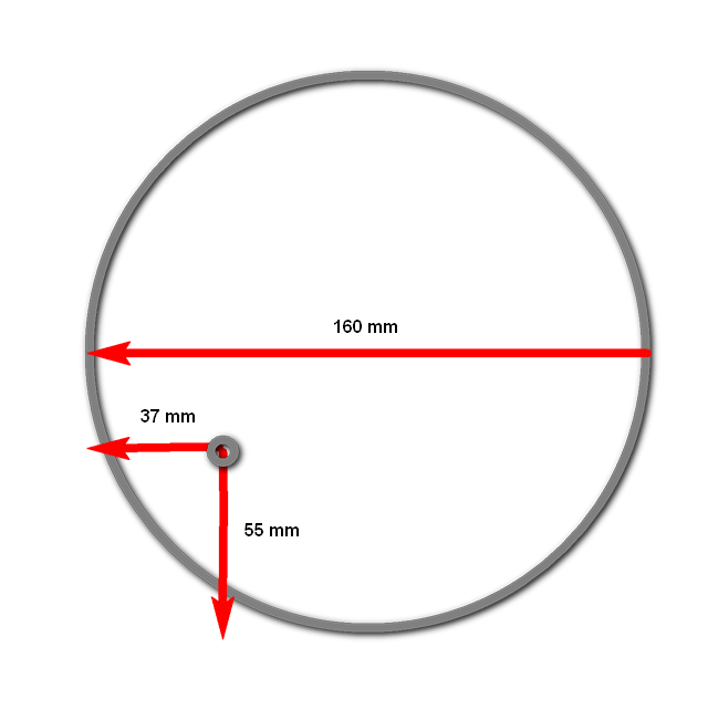
Quote Here we are... located about 8 hours
renatoa attached the following image:
|
|
|
|
| Lostx403 |
Posted on 12/25/2023 12:48 PM
|
|
Newbie Posts: 17 Joined: December 07, 2023 |
Awesome! Thanks for this, I'll make the changes tomorrow and test it out :ThumbsUp: Quote renatoa wrote: Artisan sends to TC4 a command UNITS, during initial handshaking protocol, that instructs TC4 what C or F to use. We can add handling of this command in josh code, and proper convert the numbers in the package sent as response to READ Artisan query. Will sketch below the necessary changes: Code Download source
|
|
|
|
| sloppyjosh |
Posted on 12/27/2023 10:22 PM
|
|
Newbie Posts: 30 Joined: December 01, 2023 |
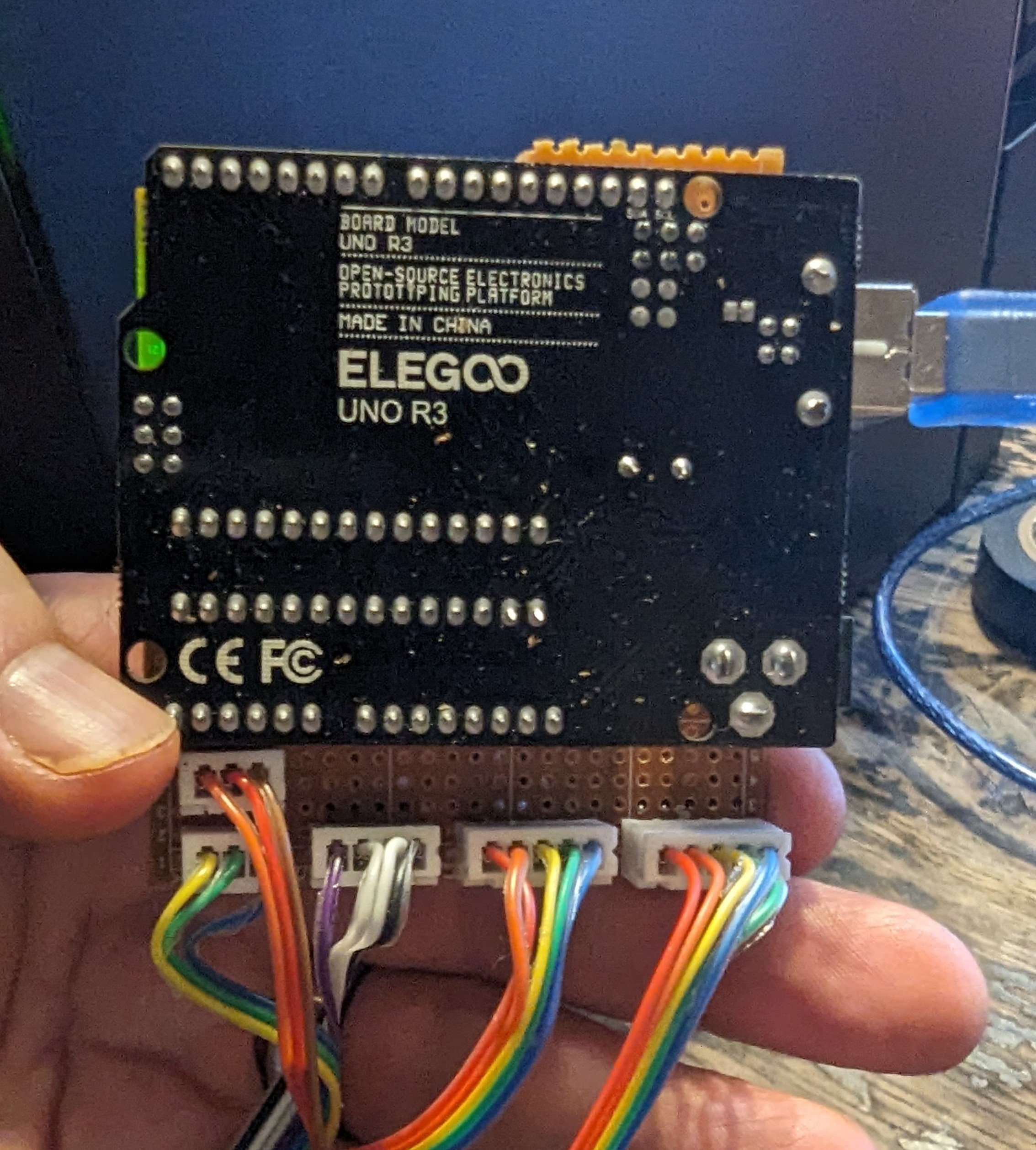
Rebuilt my homebrew controller for the skywalker. Again.. I'm pretty pleased with it now. I'm using an Uno, a board with 4 MOSFETs for speed controls, RobotDyn 20A dimmer for heat control, MAX6675 with a homebrew thermocouple for temp reading. I also added sensors for voltage and current so that I could try to get a reading on actual wattage. RobotDyn does have the zero cross circuit built in, and now that I have a scope I was able to verify that I was getting decent control of the power to the heater. I didn't write the code to control it and RobotDyn's supplied library doesn't seem to work.. I tested several others and found that the GyverDimmer library seemed to work the best. Rather than phase control, it turns the triac on for specified half periods at the zero cross. I looked at it on the scope, it's really clean. My "homebrew" thermocouple is a 1.5" stainless steel screw put through the same hole the original temp probe was in with a nut to hold it on. I then ran a bare TC to the screw through the hole the stock temp probe used for a mounting screw and used some thin bare copper wire to attach it to the screw leaving just the sensor itself exposed about 1" away from the front wall of the roaster. This probe isn't exactly ideal.. but it is really fast  .. I got some 3mm probes, but I've yet to think of a good way to mount them. .. I got some 3mm probes, but I've yet to think of a good way to mount them. I don't have the voltage or current sensors reading anything yet. I'm researching how to get those working accurately.. The issue being that when I sample, of course I can't just take an instantaneous sample.. I can get accurate readings, but doing so requires that calculate the RMS over several cycles which is too slow. Still considering the options here or if it's even worth the effort. Space is very tight inside the roaster. I have everything except the Arduino inside the back of the roaster with ribbon cable running out of the hole the USB port used to use with JST connectors attaching to a piece of perfboard which I use to make all the connections to the pins on the Arduino. See image. I did a roast today and was very pleased with how it's running. The power levels are now mapped so that heat management is intuitive and setting the power to 60 is roughly 600W, 70 is 700W, etc.. I goofed and lost the profile, It was nothing to write home about anyhow.. But I think it's in a good state that I want to hold on to for a bit to find where improvements need to be made. I'd like to do some more test roasts but I've already got more coffee roasted than I'll drink in 2 weeks.. so I'll have to pace myself out a bit.
sloppyjosh attached the following image:
|
|
|
|
| renatoa |
Posted on 12/28/2023 9:30 AM
|
|
Administrator Posts: 3131 Joined: September 30, 2016 |
RMS don't change so frequent and fast, so indeed does not worth the effort of monitoring mains... Tight space ? My memories from the first back opening, weeks ago... are about space for lots of additions...  My first thought was that maybe even a full rasp'pi stack would fit in there, and have Artisan outside on a 7" screen, as a control panel without a laptop attached...
Edited by renatoa on 12/28/2023 9:41 AM |
|
|
|
| renatoa |
Posted on 12/30/2023 5:57 AM
|
|
Administrator Posts: 3131 Joined: September 30, 2016 |
Quote sloppyjosh wrote: ...I soldered wires to the RX, TX, and Ground of the controller board. So I can plug those in to my logic analyzer or an arduino to sniff the data. ... What is peak voltage of the data pulses, 5v (Arduino) or 3.3v (ESP) ? |
|
|
|
| HarryDog |
Posted on 12/31/2023 5:15 AM
|
|
1/2 Pounder Posts: 356 Joined: July 20, 2022 |
I'm having trouble with the controller not responding intermittently so any kind of adjustment is hit or miss. I'm waiting for a reply from the ITOP store but can I adapt my manual controls from my FB to run this? Just want some reliable control at this point. |
|
|
|
| renatoa |
Posted on 12/31/2023 6:40 AM
|
|
Administrator Posts: 3131 Joined: September 30, 2016 |
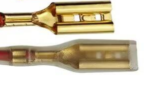
The most important part, the heater yes, can be adapted... Not even open heart surgery, heater plugs are detachable from control board PCB, and can be routed to variator. The heater wires are fitted with insulated crimp terminals, as attached, and male counterpart is soldered on PCB The fan control assume you having a 24V source and PWM controller... the plug is different than heater, low voltage low current, similar to JST type. I hope the others are still working OK... I mean start/stop drum, cooler control and temperature measurement. ...
renatoa attached the following image:
|
|
|
|
| HarryDog |
Posted on 12/31/2023 7:22 AM
|
|
1/2 Pounder Posts: 356 Joined: July 20, 2022 |
The power button faied to work once, I power cycled the unit 3 times before it started working. I have a SCR from Amazon so a triac in it I guess and the 24v with PWM controller for the blower. I have these SSR 250v AC ZGT-25LA controlled 0-10vdc was thinking of using that on the FB but current phidget module is 0-5vdc, can test on a incandescent lamp to see if it works and get a 0-10vdc module for full or more control. I can use this with Artisan as far as I'm aware. Stores open in about 3 hours to grab some parts to connect this up and test on a bulb first. |
|
|
|
| renatoa |
Posted on 12/31/2023 9:36 AM
|
|
Administrator Posts: 3131 Joined: September 30, 2016 |
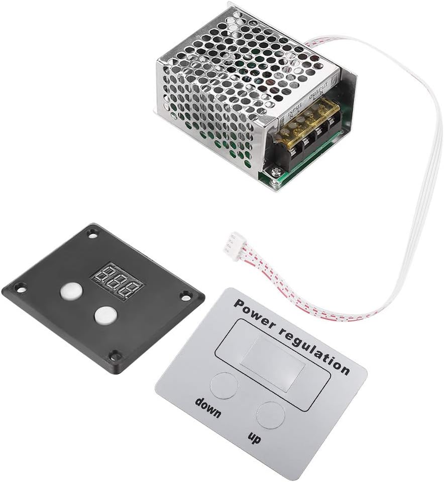
A SSR alone won't work, unless it is DC controlled by a potentiometer. When I wrote about a variator I meant something I recommend usually, using up/down button, and a percent display like the attached. Not sure how you can interface a SSR or a variator as above with Artisan without additional circuitry, based on Arduino. ...
renatoa attached the following image:
|
|
|
|
| HarryDog |
Posted on 12/31/2023 3:27 PM
|
|
1/2 Pounder Posts: 356 Joined: July 20, 2022 |
I have some Phidgets, 1048 works with Artisan for thermocouples. Not sure how many it can access? Now I tested the Vint Hub 0001_0 with Rel 1100_0 just in windows and I can turn on the light and dim it some what? But more flashing then dimming. Now that thread I posted a while ago I think is mixed up on part numbers but claim the Rel 1100 won't work well as the frequency only goes to 100Hz but I think I can control DC fans and motors with it, still need to test that. It can change Duty Cycle and Frequency. https://www.phidg...prodid=713 For the heater if I get the OUT1001_0 or the OUT1002_0 I think it might work. This video looks to have it working in Artisan? https://www.youtu...rqw_Gv3dEM |
|
|
|
| renatoa |
Posted on 01/01/2024 3:26 AM
|
|
Administrator Posts: 3131 Joined: September 30, 2016 |
Isn't simpler to do josh protocol hack, the main subject of this thread, and control the innards from artisan directly ? If we go on surgery path, then any solution ever mentioned in this site works here too, it's just a roaster, after all... |
|
|
|
| HarryDog |
Posted on 01/01/2024 6:19 AM
|
|
1/2 Pounder Posts: 356 Joined: July 20, 2022 |
Not sure of the right way to go? No experience with the Arduino stuff and none on hand but I have learning curves on all fronts. I have some manual controls and Phidgets on hand so looking at this first... No reply yet (From Store) it could be a couple more days at the earliest. |
|
|
|
| darelleman |
Posted on 01/02/2024 5:40 PM
|
|
Newbie Posts: 5 Joined: December 30, 2023 |
Hi all, I just got this roaster about a week ago and did a few assisted roasts. Now I am onto incorporating sloppyjosh's Artisan mod. Wondering if there is a way to use the original touchscreen controller to operate the roaster while using the Arduino and Artisan just for logging the roast. Would something like a USB splitter work if I use it to connect both the Arduino and the controller to the roaster? I would rather not do any soldering on the Skywalker's components themselves but I could if necessary. |
|
|
|
| HarryDog |
Posted on 01/02/2024 6:31 PM
|
|
1/2 Pounder Posts: 356 Joined: July 20, 2022 |
I think Josh said it is not actually using the USB protocol but just the connector for quick connection.
Edited by HarryDog on 01/02/2024 7:31 PM |
|
|
|
| darelleman |
Posted on 01/02/2024 7:58 PM
|
|
Newbie Posts: 5 Joined: December 30, 2023 |
That's correct the USB is just being used as a 4 pin connector basically. My question more stems from whether I can have the Original Touchscreen controller and the Arduino connected to the roaster at the same time. I am not sure if the Arduino can log while the controller drives in that setup. |
|
|
|
| renatoa |
Posted on 01/03/2024 3:25 AM
|
|
Administrator Posts: 3131 Joined: September 30, 2016 |
Sounds possible, you connect only the control panel receiving wire to Arduino, and let them talk undisturbed. This way you would just spy the temperature evolution, and plot in Artisan, with a much better RoR following. Someone could go even further, and spy both wires, i.e. having two input/read pins, instead a Rx/Tx pair. The second Rx pin would be to monitor the messages sent by control panel to the roaster, the purpose being to capture even the power/fan changes, and log them in Artisan. This implies some changes in the original josh source, not rocket science, but time for tests is needed, and an Arduino available for this job. I can sketch this code if Josh isn't listening or busy to do this fork of the original project, but all testing will be up to whoever is interested in it. |
|
|
|
| Lostx403 |
Posted on 01/03/2024 9:52 AM
|
|
Newbie Posts: 17 Joined: December 07, 2023 |
Yeah it sounds possible to do so, there's the SkywalkerSpy sketch in Josh's git repo for logging already...but why would one want to go through that just to use the included controller? To use the built in roasting profiles? Just use full Artisan control if so, the built in profiles aren't doing much and you can mimic their settings....preheat at 100% heat, drop heat to 70% and fan at 65 when you start the roast, and I can't remember if the profiles are based on time or temp to drop the temp more so and bump up the fan. Also dips your toes into controlling the roast yourself. To each their own I suppose, but if you're going through the rigmarole of using an arduino and wiring things up just for logging, might as well just use full command. |
|
|
|
| HarryDog |
Posted on 01/03/2024 11:41 AM
|
|
1/2 Pounder Posts: 356 Joined: July 20, 2022 |
Auto Roasts Medium HTR=70 and Fan 65 for washed drop at 384F HTR=65 and Fan 65 for Natural drop at 384F So I think Temp based. |
|
|
|

| Jump to Forum: |
Powered by PHP-Fusion Copyright © 2024 PHP-Fusion Inc
Released as free software without warranties under GNU Affero GPL v3
Designed with ♥ by NetriXHosted by skpacman