
Login

Shoutbox
You must login to post a message.
allenb
09/15/2024 8:05 PM
JKnight 
renatoa
09/15/2024 1:26 AM
JonnyPanic,  ?
?
?renatoa
09/13/2024 1:32 PM
Krush and jdspainhour,

renatoa
09/12/2024 1:06 AM
 , KnittyBrew
allenb
09/10/2024 1:55 PM
Welcome to all new HRO members!!!

Forum Threads
Newest Threads
Home Roaster Color M...My Sight Glass FB Ro...
Coffee Crafters Flui...
First Roaster, DIY S...
Hello from eastern PA
Hottest Threads
| Skywalker roaster... | [386] |
| Skywalker Roasts | [102] |
| War on Farmers by... | [53] |
| Using a TC4 with ... | [41] |
In Memory Of Ginny

Donations
Latest Donations
dmccallum - 10.00
JackH - 25.00
snwcmpr - 10.00
Anonymous - 2.00
Anonymous - 5.00
dmccallum - 10.00
JackH - 25.00
snwcmpr - 10.00
Anonymous - 2.00
Anonymous - 5.00
Users Online
Guests Online: 2
Members Online: 0
Total Members: 8,497
Newest Member: JKnight
Members Online: 0
Total Members: 8,497
Newest Member: JKnight
View Thread
Who is here? 1 guest(s)
 4-channel TC meter and datalogger project
|
|
| rama |
Posted on 07/30/2010 3:52 PM
|
|
Newbie  Posts: 49 Joined: April 07, 2010 |
I think these are the relevant Allied part numbers. I had to substitute a different resistor value for one (5.9k 1/2W instead of the 5.6k 1/8W if that's ok?), and the headers might need to be trimmed- not sure on the pin length's required... Allied Stk. # Mfr. Part #. 383-2077 MCP3424-E/SL 383-1869 MCP9800A0T-M/OT 409-0010 1725656 374-1770 9-146276-0 568-0292 2N3904G 896-5904 RN55D4701FB14 431-0614 1N4148-TR 613-0743 106CKH050M 852-1170 CK05BX104K 648-1682 SFR16S0005901FR500/BKN |
|
|
|
| JimG |
Posted on 07/31/2010 2:26 PM
|
|
1 1/2 Pounder  Posts: 834 Joined: October 23, 2008 |
Hi, Rama - The slightly larger resistor values should work fine. The value on those is not critical at the low output levels expected to Ot1 and Ot2. You may have to angle the 1/2W resistors upward to get them to fit the hole spacing. Hopefully, the leads on the 1/2W units will still be skinny enough to fit through the holes on the board. If you have trouble with the ones you ordered, I'd be happy to mail you a few of the resistors I've been using. Jim |
|
|
|
| randytsuch |
Posted on 07/31/2010 7:14 PM
|
 1/2 Pounder  Posts: 394 Joined: June 20, 2009 |
Quote JimG wrote: Hi, Rama - The slightly larger resistor values should work fine. The value on those is not critical at the low output levels expected to Ot1 and Ot2. You may have to angle the 1/2W resistors upward to get them to fit the hole spacing. Hopefully, the leads on the 1/2W units will still be skinny enough to fit through the holes on the board. If you have trouble with the ones you ordered, I'd be happy to mail you a few of the resistors I've been using. Jim Jim I thought the same thing when I looked at that post, but the 1/2w resistor is actually only 4.1mm long, so it will fit no problem. The other resistor is 6mm, so it should fit, but it will be a tight squeeze, you will probably need to bend the leads down right after the body. I was using a different 10uf caps, and different resistors, but that list looked fine to me. Randy |
|
|
|
| bvwelch |
Posted on 07/31/2010 7:34 PM
|
 1 1/2 Pounder Posts: 1064 Joined: December 27, 2007 |
It's possible the diameter of the 1/2 watt resistor leads will not fit thru the holes in the pcb. If that happens, a trip to your nearest Radio Shack should provide a suitable replacement. |
|
|
|
| JimG |
Posted on 07/31/2010 8:47 PM
|
|
1 1/2 Pounder Posts: 834 Joined: October 23, 2008 |
Hi, folks - All 25 of the initial TC-4 shields have been sold. After deducting PayPal fees and mailing costs, the net proceeds from all sales was $115.65. This includes $18.00 that I charged myself for the 3 boards that I kept. The total bill from GoldPhoenix was $92.03 for the boards. So there was a whopping total of $23.61 profit from this endeavor!! I sent the good folks at Coffekids.org a payment of $25 tonight to even things out. Jim |
|
|
|
| farmroast |
Posted on 08/01/2010 10:28 AM
|
|
1/2 Pounder Posts: 295 Joined: December 20, 2006 |
Quote JimG wrote: Hi, folks - All 25 of the initial TC-4 shields have been sold. After deducting PayPal fees and mailing costs, the net proceeds from all sales was $115.65. This includes $18.00 that I charged myself for the 3 boards that I kept. The total bill from GoldPhoenix was $92.03 for the boards. So there was a whopping total of $23.61 profit from this endeavor!! I sent the good folks at Coffekids.org a payment of $25 tonight to even things out. Jim :Clap: This is just another of many examples of why this community is sooo great. Ed B.
DreamRoast 1kg roaster, Levers, Hand Mills http://coffee-roa...gspot.com/ |
|
|
|
| allenb |
Posted on 08/01/2010 3:29 PM
|
 Administrator Posts: 3885 Joined: February 23, 2010 |
Quote farmroast wrote: Quote JimG wrote: Hi, folks - All 25 of the initial TC-4 shields have been sold. After deducting PayPal fees and mailing costs, the net proceeds from all sales was $115.65. This includes $18.00 that I charged myself for the 3 boards that I kept. The total bill from GoldPhoenix was $92.03 for the boards. So there was a whopping total of $23.61 profit from this endeavor!! I sent the good folks at Coffekids.org a payment of $25 tonight to even things out. Jim :Clap: This is just another of many examples of why this community is sooo great. Ed, you make a great point. There aren't many places that this can be said. It would be great to get some feedback from all who've purchased the shields as to how they're using them (stand-alone, adding to their roaster control cab, going for a PID setup like Randy's doing...) Allen 1/2 lb and 1 lb drum, Siemens Sirocco fluidbed, presspot, chemex, cajun biggin brewer from the backwoods of Louisiana
|
|
|
|
| SteveN |
Posted on 08/02/2010 12:38 PM
|
 1/4 Pounder  Posts: 127 Joined: March 16, 2010 |
Quote JimG wrote: Hi, folks - All 25 of the initial TC-4 shields have been sold. After deducting PayPal fees and mailing costs, the net proceeds from all sales was $115.65. This includes $18.00 that I charged myself for the 3 boards that I kept. The total bill from GoldPhoenix was $92.03 for the boards. So there was a whopping total of $23.61 profit from this endeavor!! I sent the good folks at Coffekids.org a payment of $25 tonight to even things out. Jim Figures.... I just found the time to read through this entire thread. Even though I understood about 50% of it, I'm still excited about the prospect of controlling my new roaster. I will continue to watch from the 'cheering' section to see how this all develops. Good luck to all. |
|
|
|
| ginny |
Posted on 08/02/2010 6:19 PM
|
 Founder Posts: 3476 Joined: October 24, 2005 |
All of you members ROCK like crazy. This is what makes HRO what it is... we are small but mighty! thank you all members for your input and support. ginnyB) Edited by ginny on 08/02/2010 6:19 PM |
|
|
|
| randytsuch |
Posted on 08/03/2010 3:01 PM
|
|
1/2 Pounder Posts: 394 Joined: June 20, 2009 |
Quote JimG wrote: Hi, Randy - I browsed your PID code and was impressed by the customization you've added for fine tuning your roasts! I doubt you could ever accomplish the same level of control using an off-the-shelf controller. You and I are working on parallel efforts (although my PID library is being written for espresso machines). FWIW, I find/found it easier to express the P, I, and D parameters this way: For proportional term, I use "Pb." This has units of degrees (can be F or C). Proportional gain, Kp, is 1 / Pb. This is nice because it demonstrates that proportional output goes to 100% when the error is larger than (i.e. outside of) Pb. For the integral term, I use rE (resets) which has units of 1/minutes. Integral gain becomes Ki = Kp * T * rE (where T = cycle period, minutes). This is nice because rE = 0 corresponds with no integral action (as compared to having to use a giant value for I to accomplish the same thing). For the derivative term, I use rA (rate). This has units of minutes. Derivative gain becomes Kd = Kp * rA / T. Obviously, it makes no difference internal to your program how you define the P, I, and D parameters. But the above is used in the Watlow controllers, as well as several others. Tuning is a lot easier for me when using parameters defined this way because I have a pretty good feel for the ranges of Pb, rE, and rA that work on different heating systems. Jim Hi Jim I was taking a little break, hence the belated reply. And honestly, I was having some trouble figuring out you reply. I was just at the Watlow site, looking at one of their user's manuals, and I think I understand you reply a little better, although I'm still not sure about some things. You show Kp in all three terms, you really use it this way? That is different from my implementation, based on my limited research into PIDs. One interesting concept I learned on the Watlow site is the "proportional band". I need to read up on that some more, and decide if I want to implement that concept in my PID. I was also trying to stay with integer math, but I may start using floating point, integer is limiting me somewhat, but I was lazy and integer is easier. Finally, thanks for the kind words about my work to date. Truthfully, I added some of the features in my PID to get the performance I want out of it, but I do think in the end it will be very flexible. Since it is designed to roast coffee, I think it will perform better then a generic PID, which is not application specific. Having the ability to tune, and add features in software makes an Arduino implemented PID very flexible and powerful. Randy |
|
|
|
| JimG |
Posted on 08/03/2010 4:46 PM
|
|
1 1/2 Pounder Posts: 834 Joined: October 23, 2008 |
Quote randytsuch wrote: You show Kp in all three terms, you really use it this way? That is different from my implementation, based on my limited research into PIDs. Yeah. That's the way I have my code set up. Proportional band (Pb) is the reciprocal of proportional gain. So if you have a Pb value equal to 15 DEG, and the error is 3 DEG, then the power output becomes 0.20 (or 20%) for the P term. Same result as if you defined Kp = 0.0667 per DEG, and multiplied the error times Kp. The nice thing about using Pb is that it has physical significance. And you know that the proportional term will be 100% when the error is larger than Pb. The sum of the past errors (used in the integral term) has units of DEG*TIME. You want to end up with a dimensionless quantity for the output, so the constant multiplying the errors sum has to have units of 1 / (DEG*TIME). So it makes sense to define Ki as having units of 1 / TIME, and then divide by Pb (which has units of DEG). Ki is a constant, so you can choose it any way you want. The references I'm using define Ki as having units of 1 / TIME, and then you divide it by Pb to get the final coefficient. Similarly for Kd. The derivative quantity has units of DEG/TIME. So if you choose your Kd as having TIME units, then Kd/Pb gives you the right units (i.e. none) for the output. Finally, if you use some of the standard tuning guides (ZN, for instance), I think they are set up expecting Ki and Kd to be in purely TIME units. Jim |
|
|
|
| randytsuch |
Posted on 08/03/2010 6:28 PM
|
|
1/2 Pounder Posts: 394 Joined: June 20, 2009 |
Quote JimG wrote: Quote randytsuch wrote: You show Kp in all three terms, you really use it this way? That is different from my implementation, based on my limited research into PIDs. Yeah. That's the way I have my code set up. Proportional band (Pb) is the reciprocal of proportional gain. So if you have a Pb value equal to 15 DEG, and the error is 3 DEG, then the power output becomes 0.20 (or 20%) for the P term. Same result as if you defined Kp = 0.0667 per DEG, and multiplied the error times Kp. The nice thing about using Pb is that it has physical significance. And you know that the proportional term will be 100% when the error is larger than Pb. The sum of the past errors (used in the integral term) has units of DEG*TIME. You want to end up with a dimensionless quantity for the output, so the constant multiplying the errors sum has to have units of 1 / (DEG*TIME). So it makes sense to define Ki as having units of 1 / TIME, and then divide by Pb (which has units of DEG). Ki is a constant, so you can choose it any way you want. The references I'm using define Ki as having units of 1 / TIME, and then you divide it by Pb to get the final coefficient. Similarly for Kd. The derivative quantity has units of DEG/TIME. So if you choose your Kd as having TIME units, then Kd/Pb gives you the right units (i.e. none) for the output. Finally, if you use some of the standard tuning guides (ZN, for instance), I think they are set up expecting Ki and Kd to be in purely TIME units. Jim Thanks for this information. It's kind of sort of starting to make sense to me. I am going to tweak my program over the next few days, and see what I can come up with. The Proportional band idea makes a lot of sense now that I understand it, and I like the idea that once you are outside the Pb, output is 100%, makes things simple and easier to understand. My end goal is to create a PID roasting program that other people can use and tweak for their setups, so I want something easy to understand, but that is tweakable enough to work in different setups. Randy |
|
|
|
| JimG |
Posted on 08/03/2010 7:43 PM
|
|
1 1/2 Pounder Posts: 834 Joined: October 23, 2008 |
Quote randytsuch wrote: My end goal is to create a PID roasting program that other people can use and tweak for their setups, so I want something easy to understand, but that is tweakable enough to work in different setups. :Clap: Which roaster(s) are your targets? I've added PID control to a P1 and to a Hottop. The popper was a lot easier to hack than the HT. But once I'd put a switch on the HT that toggles between OEM control and external control, the results were good. Jim |
|
|
|
| allenb |
Posted on 08/03/2010 8:53 PM
|
|
Administrator Posts: 3885 Joined: February 23, 2010 |
Quote JimG wrote: Quote randytsuch wrote: My end goal is to create a PID roasting program that other people can use and tweak for their setups, so I want something easy to understand, but that is tweakable enough to work in different setups. :Clap: Which roaster(s) are your targets? I've added PID control to a P1 and to a Hottop. The popper was a lot easier to hack than the HT. But once I'd put a switch on the HT that toggles between OEM control and external control, the results were good. Jim Glad to hear we're getting closer to a PID-capable Arduino/shield. It will be interesting to hear how the Arduino PID tuning goes for drum roasters. My experience with my Fuji PXR-4 has been good with fluid bed. Tuning for my drum roaster is great up to start of 1C and then falls apart. Response time from 1C to end of roast is far slower than needed to keep from severe overshooting. I read of one person solving this problem by buying a PID controller that allowed setting specific PID settings for each ramp segment but this was quite costly. I've had nearly the same issues with radiant based drum roasters. 1/2 lb and 1 lb drum, Siemens Sirocco fluidbed, presspot, chemex, cajun biggin brewer from the backwoods of Louisiana
|
|
|
|
| JimG |
Posted on 08/03/2010 10:01 PM
|
|
1 1/2 Pounder Posts: 834 Joined: October 23, 2008 |
Quote allenb wrote:Glad to hear we're getting closer to a PID-capable Arduino/shield. The hardware we have now can support a fairly sophisticated controller. And the software libraries posted here http://code.googl...c4-shield/ provide the back end support needed to read up to 4 channels of type K input, and to drive 2 SSR's using PWM. So "all" that's left is to write the PID application software  Jim |
|
|
|
| randytsuch |
Posted on 08/04/2010 9:44 AM
|
|
1/2 Pounder Posts: 394 Joined: June 20, 2009 |
Quote JimG wrote: Which roaster(s) are your targets? I've added PID control to a P1 and to a Hottop. The popper was a lot easier to hack than the HT. But once I'd put a switch on the HT that toggles between OEM control and external control, the results were good. Jim I only have poppers for roasting, a P1 and two Pumpers. I use a Pumper as my main roaster, and it has basically the same guts as the P1. So, I can only try it on my Pumper, but am hoping the program can be generic enough so others can tweak some parameters to suit their application. I would think fluid air roasters, like a popper would be the hardest to control, since the only thermal mass is in the beans. Since I have never worked with a drum roaster, I may not appreciate the issues a drum would have. For things like supporting different parameters after 1st crack, I have the program set up to support different parameters at the end, versus the beginning of the roast. It is easy to change where the switch occurs. Right now, only a couple of parameters are switched, but that would be easy to expand. I still have some work to do on my program, hopefully I can do more later this week, and over the weekend. Randy |
|
|
|
| randytsuch |
Posted on 08/04/2010 5:45 PM
|
|
1/2 Pounder Posts: 394 Joined: June 20, 2009 |
So I have a new question for the software guru's out there. Right now, my PID program supports one hard coded profile. I would like to add a user interface (thinking of an analog joystick), and let you easily select maybe 1 of 10 profiles. So, once you have a profile figured out for a bean, it will be easy to start it. I am using 4 different arrays to store the profile information, temp, time, offset (a fudge factor) and fan speed. I don't know how to hardcode in these 10 different profiles, and then select one as the runtime profile, with 4 arrays to deal with. I am thinking I have to deal with 40 arrays, and figure out how to find the 4 I want to use. I stuck all the temp/time/offset/fan information for each profile into one array per. Then, I would just have 10 arrays, and I could figure that out I think, but I think it will be more user friendly to have 4 arrays per profile, each with it's own type of information to set up. One thing I just thought of was I could make 4 large arrays, where I stick in 10 temp profiles into one array, 10 time profiles into another, etc. I could work with that, but it may be a little more confusing then 40 arrays, but then again maybe not. Any advice would be appreciated.' EDIT I did a little research, and I think I figured it out. But, I need to work with pointers, and set up my program to use pointers to index into my arrays. Last time I worked with pointers (many years ago), I had some problems, but eventually figured it out. Hopefully I can do this without pulling too many hairs out. Randy Edited by randytsuch on 08/04/2010 6:27 PM |
|
|
|
| allenb |
Posted on 08/04/2010 8:35 PM
|
|
Administrator Posts: 3885 Joined: February 23, 2010 |
Quote randytsuch wrote: I would think fluid air roasters, like a popper would be the hardest to control, since the only thermal mass is in the beans. Since I have never worked with a drum roaster, I may not appreciate the issues a drum would have. For things like supporting different parameters after 1st crack, I have the program set up to support different parameters at the end, versus the beginning of the roast. It is easy to change where the switch occurs. Right now, only a couple of parameters are switched, but that would be easy to expand. Randy The reason drums are more difficult is the long lag time from power level change to response in BT. A typical PID controller seems to forget what it was doing by the time the beans come around. I'm currently just controlling ET with a few ramp segments and generally get pretty good results as long as I don't buy a new crop bean with higher than average moisture content. I would suggest staying the course with air roasting until it's perfected and folks are getting great results before tackling PID for drum roasters. Good luck with the programming, Allen 1/2 lb and 1 lb drum, Siemens Sirocco fluidbed, presspot, chemex, cajun biggin brewer from the backwoods of Louisiana
|
|
|
|
| JimG |
Posted on 08/04/2010 8:37 PM
|
|
1 1/2 Pounder Posts: 834 Joined: October 23, 2008 |
My "unencumbered by thought" suggestion (code shown is intended for execution on the Arduino): Code Download source #define NMAX 15 // ?? max. number of breaks in profile Write all of the profiles you want into the 24LC512 EEPROM on the V2.0 board (or put it on a $6.00 Adafruit prototyping board). Use the mcEEPROM library I posted on the googlecode site to read a profile back in from the EEPROM: Code Download source #define FIRST_PROFILE_ADDR 1024 // or where ever you decide to write it Once you've read a profile struct from the EEPROM, check the ID and see if it is the one you want. If not: Code Download source ptr += sizeof( myprofile ); Continue to step through the stored profiles until you find the one you want. Here's a link to the mcEEPROM library header: http://code.googl...mcEEPROM.h Here's a link to a demo program that shows how to read/write struct's from the EEPROM: http://code.googl...EPROM3.pde Jim |
|
|
|
| randytsuch |
Posted on 08/05/2010 7:36 PM
|
|
1/2 Pounder Posts: 394 Joined: June 20, 2009 |
Hi Jim thanks for the very detailed response. I'm not sure I really need to use an eeprom, I have about 1/2 the program space left the arduino. But, setting up a structure to hold the profile information makes a lot of sense, I'll proably convert my code to use structures after I get my basic PID working better. I also just found the sizeof function the other day, and want to start using that instead of hard coding the size of things into my code. BTW, when I look at your code, I feel like such a hack :BowDown: Good thing I'm just doing this as a hobby. Randy |
|
|
|
| JimG |
Posted on 08/06/2010 9:48 AM
|
|
1 1/2 Pounder Posts: 834 Joined: October 23, 2008 |
Quote randytsuch wrote:I'm not sure I really need to use an eeprom, I have about 1/2 the program space left the arduino. That should work, too. I guess you'd create an array of struct's, and then insert the values in a series of initialization statements in your PID sketch for the Arduino. OTOH, the EEPROM turned out to be fairly painless to get up and running on the Adafruit prototyping board. This board has pads for soldering a surface mount chip. Then the connections needed are +5V, GND, AIN4, and AIN5. I used fly wires and it went together pretty quick. If you used an EEPROM, then you could store your profiles in a PC text file and write a Processing sketch that would read the file(s) and send them over the serial line to the Arduino. A simple (I think) Arduino sketch could read the serial port and write the profiles to the EEPROM. I like dreaming up projects for someone else  Jim |
|
|
|
| randytsuch |
Posted on 08/06/2010 11:01 AM
|
|
1/2 Pounder Posts: 394 Joined: June 20, 2009 |
Quote JimG wrote: Quote randytsuch wrote:I'm not sure I really need to use an eeprom, I have about 1/2 the program space left the arduino. That should work, too. I guess you'd create an array of struct's, and then insert the values in a series of initialization statements in your PID sketch for the Arduino. OTOH, the EEPROM turned out to be fairly painless to get up and running on the Adafruit prototyping board. This board has pads for soldering a surface mount chip. Then the connections needed are +5V, GND, AIN4, and AIN5. I used fly wires and it went together pretty quick. If you used an EEPROM, then you could store your profiles in a PC text file and write a Processing sketch that would read the file(s) and send them over the serial line to the Arduino. A simple (I think) Arduino sketch could read the serial port and write the profiles to the EEPROM. I like dreaming up projects for someone else Jim I would like to be able to edit the profile files on my laptop, and have be able easily send them from the laptop to the arduino. I guess my one reservation for the EEPROM is that it would require anyone who bought one of the 25 rev 1 boards to add an EEPROM to use my PID program. I was trying to avoid that, but since it's easy to do, I will reconsider. Randy |
|
|
|
| bvwelch |
Posted on 08/06/2010 12:32 PM
|
|
1 1/2 Pounder Posts: 1064 Joined: December 27, 2007 |
Randy - I like your idea of being able to choose from several pre-compiled profiles. If you don't want to use the external eeprom, you could try this: Develop your profiles in Excel, write out as CSV, and then use a little script to convert that into a C "include file". Then you just recompile your 'sketch' and reload into your Arduino anytime you want to tweak the profiles. |
|
|
|
| randytsuch |
Posted on 08/06/2010 1:03 PM
|
|
1/2 Pounder Posts: 394 Joined: June 20, 2009 |
Quote bvwelch wrote: Randy - I like your idea of being able to choose from several pre-compiled profiles. If you don't want to use the external eeprom, you could try this: Develop your profiles in Excel, write out as CSV, and then use a little script to convert that into a C "include file". Then you just recompile your 'sketch' and reload into your Arduino anytime you want to tweak the profiles. Hi Bill I like that suggestion, because I currently have my profiles in Excel, so it would be convenient to me to keep them in Excel. But, I have to figure out the rest of what you described, I have no idea how to do it right now. BTW, on a different topic, I don't know how to check in updated files into Kona, so I haven't been. Randy |
|
|
|
| rama |
Posted on 08/06/2010 7:13 PM
|
|
Newbie Posts: 49 Joined: April 07, 2010 |
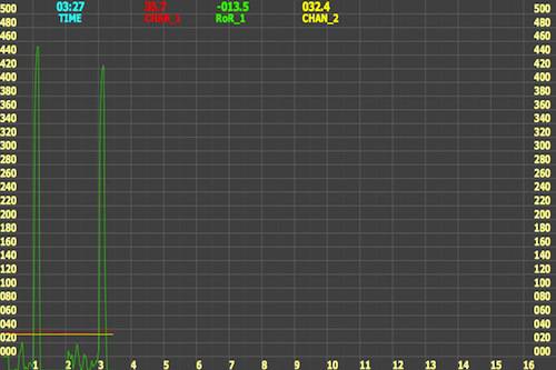
I've got the shield built out, fired it up and am able to see data via the capture app in Processing. You guys did a great job making this simple, thanks! When I hold the thermocouple between my fingers, I see an immediate response in the RoR on the graph. See attached, where I grab the TC at 1:00 and again at 3:00. However, on startup, I get: "Error configuring mcp9800". Sounds straightforward enough- maybe I foobar'ed the soldering of this tiny surface mount component, even though it looks ok. But I don't get why the shield would respond as expected (at least in this simple test) if that were the case. Seems it shouldn't work at all if the 9800 was truly miswired? I added some debugging as such: if (a != A_BITS) { Serial.println("# Error configuring mcp9800"); Serial.print("# a value: "); Serial.println(a); Serial.print("# A_BITS value: "); Serial.println(A_BITS); which generated the output: ... # time,ambient,T0,rate0,T1,rate1 # Error configuring mcp9800 # a value: ˇ # A_BITS value: 64 6.0,32.0,32.8,0.0,32.4,0.0 7.0,32.0,32.8,0.0,32.4,0.0 8.0,32.0,32.8,0.0,32.4,0.0 ... Ideas?
rama attached the following image:
|
|
|
|

| Jump to Forum: |
Powered by PHP-Fusion Copyright © 2024 PHP-Fusion Inc
Released as free software without warranties under GNU Affero GPL v3
Designed with ♥ by NetriXHosted by skpacman