
Login

Shoutbox
You must login to post a message.
allenb
09/07/2024 10:25 AM
1trakmind 
renatoa
09/06/2024 9:41 AM
 , n0n4m3
renatoa
09/05/2024 2:35 AM
GabiZ and pawantanwar, 
renatoa
09/02/2024 6:15 AM
 , robair
allenb
09/01/2024 3:51 PM
clarkwisconsin
Forum Threads
Newest Threads
My Sight Glass FB Ro...Guatemala Acetenango...
Green coffee reviews
Air vs Drum roaster
War on Farmers by Su...
Hottest Threads
| Skywalker, the AL... | [263] |
| War on Farmers by... | [53] |
| Green coffee reviews | [10] |
| Help and recommen... | [10] |
In Memory Of Ginny

Donations
Latest Donations
dmccallum - 10.00
JackH - 25.00
snwcmpr - 10.00
Anonymous - 2.00
Anonymous - 5.00
dmccallum - 10.00
JackH - 25.00
snwcmpr - 10.00
Anonymous - 2.00
Anonymous - 5.00
Users Online
Guests Online: 4
Members Online: 0
Total Members: 8,478
Newest Member: 1trakmind
Members Online: 0
Total Members: 8,478
Newest Member: 1trakmind
View Thread
Who is here? 9 guest(s)
 Skywalker roaster mods
|
|
| renatoa |
Posted on 07/06/2024 2:09 AM
|
|
Administrator Posts: 3131 Joined: September 30, 2016 |
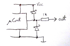
When powered from USB, the regulator is bypassed, thus board is running at 5V. You don't want board powered at 3.3V. this means you need level shifters on D2/3, as the pulses coming from skywalker are 5V. So there is no absolute need to power the board from skywalker, but... with a warn ! You should always connect the USB first, THEN power skywalker. And DO NOT disconnect USB from laptop when roast finishes, without first unplugging skywalker from the mains. If the later happens, you can experience the so called phantom powering of the board, via data lines, which cold damage board, not instantly but in time. This issue can be easily fixed placing a 2.2...4.7k resistor in series on each data line, i.e. D2/3. As sketched in the image attached. Diodes aren't required, they are already existing, embedded into the microprocessor.
renatoa attached the following image:
Edited by renatoa on 07/06/2024 11:28 AM |
|
|
|
| Dan N |
Posted on 07/06/2024 8:44 AM
|
|
Newbie  Posts: 30 Joined: January 06, 2024 |
There are 2 versions of Pro Micro: 5V/16MHz and 3.3V/8Mhz. Make sure you have the 5V/16Mhz version. I just realized the Pro Micro power hookup is different from the others. Unlike the Nano, the Pro Micro can't have a connection to external 5V and USB 5V at the same time, so do not connect anything (like 5V from the roaster USB) to VCC pin. That also confirms renatoa's recommendation in the post above to always leave the laptop connected while the Skywalker is plugged in. Pro Micro also has a jumper (J1) that may need to be shorted to bypass the regulator when using USB power only. It could be different for the different clones so check the docs for your board. Sorry, if I'd known about all this complexity I wouldn't have recommended the Pro Micro. Definitely not beginner friendly. I do recommend the Nano for a small build. |
|
|
|
| billsey |
Posted on 07/06/2024 12:37 PM
|
|
Newbie Posts: 48 Joined: August 11, 2015 |
The ones I got are 5V, so that isn't an issue. I believe I can just use three wires to connect, D2, D3 and GND. I'm going to connect that up and see what happens, I expect it will work correctly. I am going to have to use wires to make that connection, the three holes in the Pro Micro do line up with the three pins on the USB, but at right angles to where I want to USB connection to the computer. I think Ill use double sticky foam tape to hold the Pro Micro in place until someone designs a box for this all. It's just a slight bit larger than the USB Y configuration I started with, because the Pro Micro is just a bit longer than the USB female board. I'll see if I can post a pic once it's wired up... |
|
|
|
| renatoa |
Posted on 07/06/2024 2:16 PM
|
|
Administrator Posts: 3131 Joined: September 30, 2016 |
The phantom powering IS a known issue for ANY Arduino board, is not a specific case for the micro board only. Not related to 3.3V powering, happens for 5V boards too. It happens when any Arduino data pins are connected to another board powered from other source. |
|
|
|
| billsey |
Posted on 07/13/2024 7:08 PM
|
|
Newbie Posts: 48 Joined: August 11, 2015 |
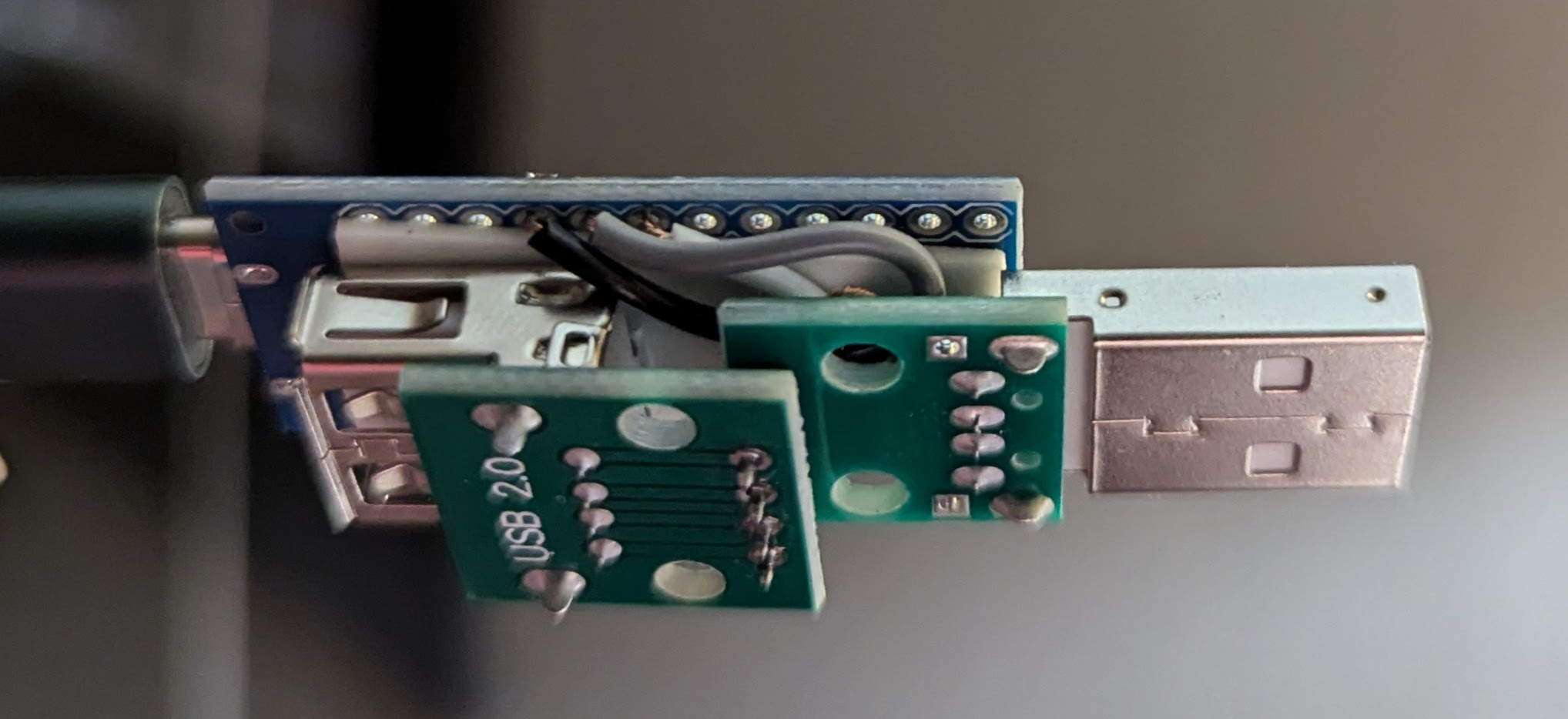
Quote renatoa wrote: The phantom powering IS a known issue for ANY Arduino board, is not a specific case for the micro board only. Not related to 3.3V powering, happens for 5V boards too. It happens when any Arduino data pins are connected to another board powered from other source. OK, I promised pictures a few days ago, but didn't get around to soldering anything until today. Let's see if the board will let me attach them today.
billsey attached the following image:
|
|
|
|
| billsey |
Posted on 07/13/2024 7:10 PM
|
|
Newbie Posts: 48 Joined: August 11, 2015 |
Quote billsey wrote: OK, I promised pictures a few days ago, but didn't get around to soldering anything until today. Let's see if the board will let me attach them today. That gave me one picture, let's try the other... Nope, same error "attachment type not allowed" even though it's a jpg just like the last one. :( |
|
|
|
| renatoa |
Posted on 07/14/2024 12:58 AM
|
|
Administrator Posts: 3131 Joined: September 30, 2016 |
Smaller than 10M ? Any functional test so far ? |
|
|
|
| billsey |
Posted on 07/14/2024 6:31 PM
|
|
Newbie Posts: 48 Joined: August 11, 2015 |
215KB vs. 218KB. I was going to try a batch where I just monitored using Artisan today, but ended up playing pool instead. Maybe tomorrow... |
|
|
|
| billsey |
Posted on 07/14/2024 10:33 PM
|
|
Newbie Posts: 48 Joined: August 11, 2015 |
OK, first try was a rousing ... less than success. Artisan could talk with the Pro Micro and the roaster display came up fine, but when I told Artisan to Start the drum started spinning with a 100% heat setting and the roaster didn't actually heat. After a bit of fiddling I got the roaster to give me an E3 to say it wasn't communicating with the temperature sensor. My guess is I have the D+ and D- lines swapped, since the documentation doesn't really tell you which is supposed to connect to D2 and which to D3, except through wiring colors. I opened two different USB cables over the last couple of week and they both had different colored wires than illustrated, so I ended up guessing. I'll do a rewire tomorrow or the next day with those swapped to see if it makes a difference. |
|
|
|
| renatoa |
Posted on 07/15/2024 3:19 AM
|
|
Administrator Posts: 3131 Joined: September 30, 2016 |
E3 is drum not working/rotating, unrelated to sensor/temperature. That is E1. Supposed you will try the Spy version first, before trying control from Artisan, which is tricky. |
|
|
|
| billsey |
Posted on 07/15/2024 1:03 PM
|
|
Newbie Posts: 48 Joined: August 11, 2015 |
I was hoping I wouldn't have to flash a different version in order to spy... Thinking of the main version just watching without doing any control. |
|
|
|
| billsey |
Posted on 07/17/2024 3:14 PM
|
|
Newbie Posts: 48 Joined: August 11, 2015 |
OK, I flashed the spy version and swapped those two digital lines, then ran a roast. Nothing came through at all. Either I messed up one of the connections or I had the wiring right before. Back to the drawing board to test the wiring... |
|
|
|
| renatoa |
Posted on 07/18/2024 1:12 AM
|
|
Administrator Posts: 3131 Joined: September 30, 2016 |
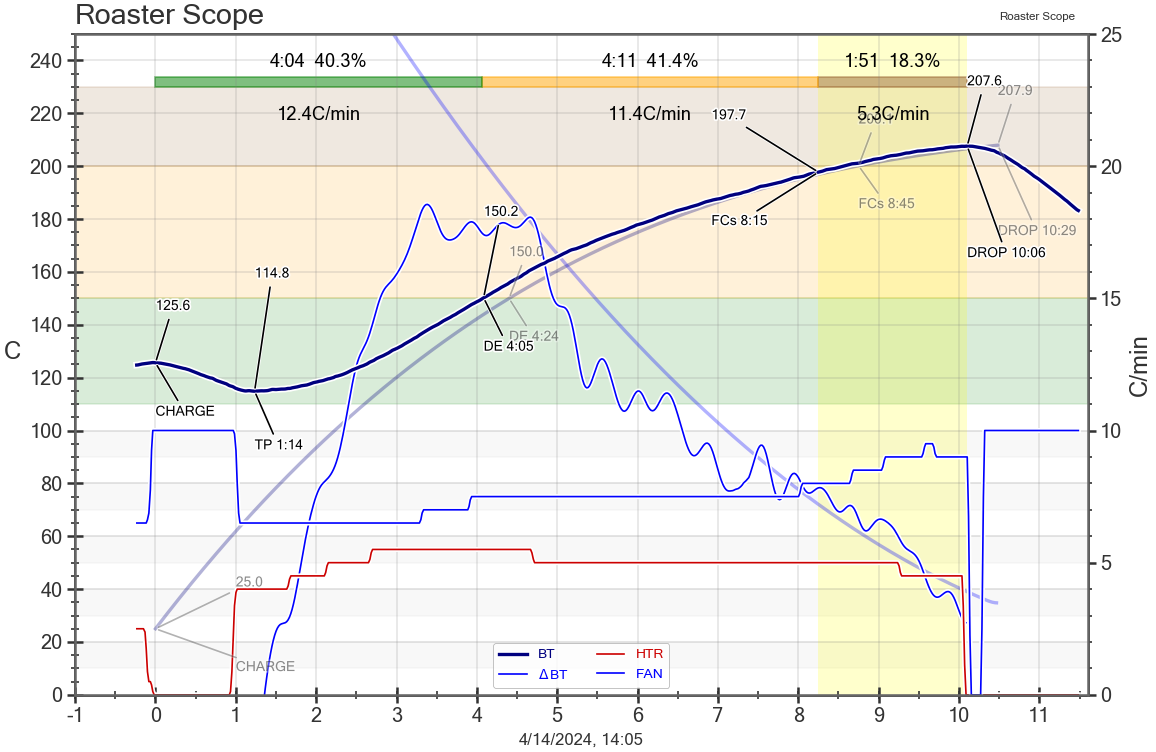
Quote For the first builds, to accommodate with the new routine of roasting tethered, without wasting beans, I simply simulated a roast with empty machine, trying to follow a profile, just to train my senses with machine response to different commands. Attached is a sample of such empty machine "roast cycle". Except for the lower power levels, anything else is same as for a real roast. Also, lower charge temperature was required, to be able to simulate a TP as close to machine loaded. For this reason I cut the power and maxed up the fan in the first minute.
renatoa attached the following image:
|
|
|
|
| billsey |
Posted on 07/18/2024 1:24 PM
|
|
Newbie Posts: 48 Joined: August 11, 2015 |
Ah, but since so far I am not seeing any of the data, my curve is completely flat at the bottom of the scale. I should be able to turn the roaster on, so the display is showing ambient temperature (say 23C), hit the start button on Roaster Scope and see that 23C as a flat line in the display, correct? |
|
|
|
| billsey |
Posted on 07/24/2024 9:01 PM
|
|
Newbie Posts: 48 Joined: August 11, 2015 |
OK, more testing... For some reason when I plug the roaster in it lights the LED on the Arduino even without the Vcc connected to anything. Likely it's seeing power on those two data pins. No big deal, just surprising. When I plug it into my laptop with SkywalkerSpy flashed it doesn't see ambient temperature even when I tell Artisan to start. When I flash SkyCommand instead I do see ambient temperature, but it wants to start the drum for me when I start. So, I'm not getting what I hoped for which was to be able to monitor with Artisan or control with Artisan without reflashing the Arduino. I'll see if I can delve into the code to try and figure out why the spy software doesn't seem to be working at all... With the roaster plugged in, the Arduino connected but nothing turned on I'm reading 2.5V or so with my VOM between either D2 and GND or D3 and GND. I believe that is why the LED lights. There is 5V between VBUS and GND on the 'notUSB' port as expected, but I don't have VBUS connected to anything. It makes perfect sense that there be power available there since you have to have power to be able to turn the system on with the controller. My guess is the data pins are getting data signals even before you turn everything on, which explains the ~2.5V my meter shows. What I really want is to monitor and graph using Artisan by default, and either take over control in the middle of a roast or use full control during the roast without having to either switch out the Arduino or flash new software to it. Hopefully that will be doable eventually. My initial thoughts regarding the VBUS connection on the 'notUSB' port seem to be born out, it's not needed to receive or send data to the Arduino and from there to the roaster, though it could be used to run the Arduino without a laptop connected. Unfortunately, without a separate computer connected it's kind of tough to run Artisan for control, so you will likely be always using the USB connection to power the Arduino. At least, I don't think there's a version of Artisan that will run on the Arduino... That's more of a Pi thing, or a dedicated computer. |
|
|
|
| billsey |
Posted on 07/24/2024 9:07 PM
|
|
Newbie Posts: 48 Joined: August 11, 2015 |
OK, first glance at the code... SkyCommand sets the serial port at 115200, SkywalkerSpy sets it to 9600 instead. That could easily be why I'm not seeing anything. |
|
|
|
| DancingDog |
Posted on 07/25/2024 12:43 AM
|
|
Newbie Posts: 2 Joined: February 24, 2024 |
Quote billsey wrote: OK, more testing... For some reason when I plug the roaster in it lights the LED on the Arduino even without the Vcc connected to anything. Likely it's seeing power on those two data pins. No big deal, just surprising. This is a known issue, and will eventually fry the Arduino. Best practice is to power the Arduino first, by plugging it into the computer's USB before plugging the modified data cable into the roaster; this prevents the backfeed through the data pins. |
|
|
|
| renatoa |
Posted on 07/25/2024 12:56 AM
|
|
Administrator Posts: 3131 Joined: September 30, 2016 |
Quote billsey wrote: OK, first glance at the code... SkyCommand sets the serial port at 115200, SkywalkerSpy sets it to 9600 instead. That could easily be why I'm not seeing anything. Perhaps do you mean josh original spy... I thought you will be using mine, which is 115200, just checked. |
|
|
|
| renatoa |
Posted on 07/25/2024 12:59 AM
|
|
Administrator Posts: 3131 Joined: September 30, 2016 |
Quote billsey wrote: OK, more testing... For some reason when I plug the roaster in it lights the LED on the Arduino even without the Vcc connected to anything. Likely it's seeing power on those two data pins. No big deal, just surprising. .... Really? Wasn't this beaten to dead last page... the ghost powering issue... and seems not read... As DancingDog said... |
|
|
|
| billsey |
Posted on 07/25/2024 10:11 AM
|
|
Newbie Posts: 48 Joined: August 11, 2015 |
Quote renatoa wrote: Perhaps do you mean josh original spy... I thought you will be using mine, which is 115200, just checked. I'm using the one on the jmoore52 github page. Where is yours? |
|
|
|
| billsey |
Posted on 07/25/2024 10:14 AM
|
|
Newbie Posts: 48 Joined: August 11, 2015 |
Quote DancingDog wrote:This is a known issue, and will eventually fry the Arduino. Best practice is to power the Arduino first, by plugging it into the computer's USB before plugging the modified data cable into the roaster; this prevents the backfeed through the data pins. Good to know, I likely skipped over that part of the discussion back when I initially read this thread. I only plug the roaster in when I'm ready to start a roast session, since it takes up so much room in my small kitchen, so that shouldn't be a problem over the long term. I'll just connect the laptop first, then plug the roaster in. |
|
|
|
| renatoa |
Posted on 07/25/2024 12:01 PM
|
|
Administrator Posts: 3131 Joined: September 30, 2016 |
Quote billsey wrote: Quote renatoa wrote: Perhaps do you mean josh original spy... I thought you will be using mine, which is 115200, just checked. I'm using the one on the jmoore52 github page. Where is yours? post #220 https://homeroast...post_78398 |
|
|
|
| Robotic Kitten |
Posted on 07/25/2024 4:18 PM
|
|
Newbie Posts: 24 Joined: December 04, 2023 |
Quote sloppyjosh wrote: Of course, these may not be the raw values from the ADC.. maybe they've been transformed somehow. but it just doesn't make sense. I think I figured it out, which matches my experimentation. 1. The Values are raw ADC values 2. the ADC is 10bit 3. The temperature probe is a 230K NTC thermistor, The values from https://www.analo...ousing.pdf are matching perfectly 4. The first two bytes (10 bits ADC Data) is using the 5v - 1.875K - NTC divider 5. The second two bytes (10 bit ADC Data) is using the 5v - 30K - NTC divider In other words, that 2K R16 resistor is an additional pull up to 5v to increase the resolution for the higher temps, when NTC resistance drops to single kilo ohms values. The formula for the first two bytes = 0x3FF * Rntc/(1875 + Rntc) The formula for the 2nd two bytes = 0x3FF * Rntc/(30000 + Rntc) I used three regular resistors instead of NTC and got the following: NTC=11.82K, Reported Temp: 103C, values: 0x373, 0x122, measured voltages high and low: 4.2V & 1.4V NTC=1.51K, Reported Temp: 181C, values: 0x1C9, 0x031, measured voltages high and low: 2.3V & 0.23V NTC=5.52K, Reported Temp: 129C, values: 0x2FC, 0x0A0, measured voltages high and low: 3.8V & 0.8V Edited by Robotic Kitten on 07/25/2024 4:54 PM |
|
|
|
| Robotic Kitten |
Posted on 07/25/2024 4:43 PM
|
|
Newbie Posts: 24 Joined: December 04, 2023 |
BTW, decided to build me a replacement board, based on F412 MCU. Doh, why it wouldn't let me attach a .jpg or .png https://1drv.ms/i...w?e=sjmXzZ Edited by renatoa on 07/26/2024 1:25 AM |
|
|
|
| renatoa |
Posted on 07/26/2024 4:40 AM
|
|
Administrator Posts: 3131 Joined: September 30, 2016 |
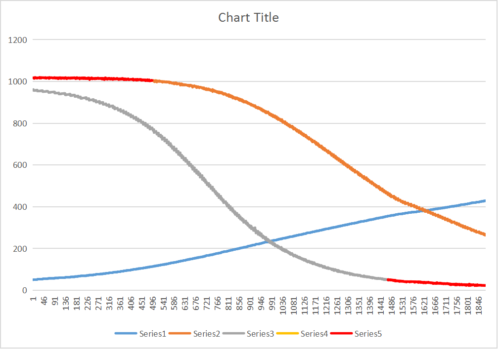
Quote Before the long story following... thank you to resurrect my memories on this subject... this was a post I prepared months ago, in the winter, then... just when I planned to post, dropped the bomb with the fire due to undersized heatsink of the SCR. Sudden, all the focus was stolen by that issue and ways how to fix, so I forgot about the NTC values processing. At that time I got similar findings, but different values for components, as early reported in the beginning of this thread. Seems there were various generations of hardware. My NTC is 5k, and the voltage at the output of 30K divisor confirm this, it is 0.7V for ambient temperature. i.e. 5V * 5/(30+5) As a result, my guess was the ADC is 12 bits, used for only 1/4 of the full scale, as a 10 bit ADC The two divisors purpose is right, to create two measurement ranges, each range offering a better resolution than the full range with single divisor. Someone early in the thread guessed that the initial electronics could be of a water boiler... could be right, because one of the measurement ranges has maximum resolution up to 110C degrees, from there the resolution decrease quickly. So they added a second divisor, for the 115-250C range. As you can guess, the high temperature mode has a complementary behavior to the boiling water mode, the low resolution is now in the lower temperatures range. So each range has useful data at one end, and garbage at the other end. To put this info into a picture, that worth... many words... check the attached graph. For each of the two curves, the red section is practically unusable. Almost flat could mean less than an ADC step for a degree (Celsius). We want a curve section as steeper as possible, for maximum resolution. Actually, unusable is not the exact term... it is even dangerous to use data from those sections in a single decoding formula, because the values in the red areas acts as noise for the useful data from the other dataset, when performing temperature decoding. For this reason I wrote an alternative calculateTemp() function, using data from a set only for each subrange, and two simpler 3rd degree polynomials, instead the original 4th degree using both datasets simultaneously. The code for the two polynomials is below: Code Download source if (intx > 836 || inty > 221) The complete function code can be found in my custom Spy sketch from the archive attached to post #220. The result is a smoother curve and faster computations. Actually, there no detectable difference in real life, so don't hurry to replace yours. I did it just as a brick in something bigger, where I needed better temperature resolution and accuracy than current decoding. As a side note, decoding speed is the last thing to worry, each temperature packet has a trailing gap of 11ms (11.000us) , more than enough to run a lot of processing code. The actual code eats only 600 us of this interval, to have a reference how many things can be done additional to temperature decoding. ~~~
renatoa attached the following image:
Edited by renatoa on 08/11/2024 1:50 AM |
|
|
|

| Jump to Forum: |
Powered by PHP-Fusion Copyright © 2024 PHP-Fusion Inc
Released as free software without warranties under GNU Affero GPL v3
Designed with ♥ by NetriXHosted by skpacman