
Login

Shoutbox
You must login to post a message.
allenb
09/19/2024 11:19 AM
Firaollemecha 
allenb
09/15/2024 8:05 PM
JKnight
renatoa
09/15/2024 1:26 AM
JonnyPanic,  ?
?
?renatoa
09/13/2024 1:32 PM
Krush and jdspainhour,

renatoa
09/12/2024 1:06 AM
 , KnittyBrew
Forum Threads
Newest Threads
Hello from eastern PAHome Roaster Color M...
My Sight Glass FB Ro...
Coffee Crafters Flui...
First Roaster, DIY S...
Hottest Threads
| Skywalker roaster... | [386] |
| Skywalker Roasts | [102] |
| Using a TC4 with ... | [41] |
| Green coffee reviews | [10] |
In Memory Of Ginny

Donations
Latest Donations
dmccallum - 10.00
JackH - 25.00
snwcmpr - 10.00
Anonymous - 2.00
Anonymous - 5.00
dmccallum - 10.00
JackH - 25.00
snwcmpr - 10.00
Anonymous - 2.00
Anonymous - 5.00
Users Online
Guests Online: 3
Members Online: 0
Total Members: 8,498
Newest Member: Firaollemecha
Members Online: 0
Total Members: 8,498
Newest Member: Firaollemecha
View Thread
Who is here? 1 guest(s)
 4-channel TC meter and datalogger project
|
|
| JimG |
Posted on 08/24/2010 7:27 AM
|
|
1 1/2 Pounder  Posts: 834 Joined: October 23, 2008 |
The new (V3.00) PCB's arrived in the mail yesterday from GoldPhoenix. I need to assemble one and test it. As soon as that is done, hopefully by the weekend, I'll put the link back up where people can order bare PCB's. Jim |
|
|
|
| scooter |
Posted on 08/26/2010 7:35 AM
|
|
Newbie  Posts: 2 Joined: August 16, 2010 |
Gday guys, only recently joined but loving this thread! A bit intimidated by some of the technical factors, esp. the SMD componentry, but I'm very interested in the project, and plan to place an order when the link's back up. Cheers all..................Sean |
|
|
|
| allenb |
Posted on 08/26/2010 11:49 AM
|
 Administrator Posts: 3885 Joined: February 23, 2010 |
Sean, Here's a link Bill had suggested a while back on SMD soldering. It's linked on Sparkfun's site and is a grouped set of Youtube videos showing how to solder these little guys. Tacking in place, soldering and wicking up the excess solder is shown pretty well in some of them. When you open the link, scroll to the bottom of the group. Also, the guy commenting on Sparkfun's site recommends some fancy soldering gear but I was able to get it done with a $15.00 15 watt radio shack model, a roll of 1/8" wide wick, fine diameter solder, magnifying visor, good set of tweezers, quite a few cups of good coffee and a little patience. http://www.youtub...arkfun#g/u Allen 1/2 lb and 1 lb drum, Siemens Sirocco fluidbed, presspot, chemex, cajun biggin brewer from the backwoods of Louisiana
|
|
|
|
| JimG |
Posted on 08/27/2010 7:43 AM
|
|
1 1/2 Pounder Posts: 834 Joined: October 23, 2008 |
Only the MCP9800 ambient sensor is even moderately difficult to solder. Both the ADC chip and the EEPROM chip are also SMD, but I've not had any problems -- and I am definitely NOT an expert "solderer." I dab a little rosin flux on the pads first, and this seems to help the solder figure out where it is wanted. I saw a video online where the guy "pushes" the solder into each joint, moving the iron slightly from the back of the pad toward the chip. This technique works well for me. Using the solder wick works great, too. But if I wipe off my tip before soldering each pin I usually don't get any bridges. Jim |
|
|
|
| JimG |
Posted on 08/29/2010 4:34 PM
|
|
1 1/2 Pounder Posts: 834 Joined: October 23, 2008 |
Have run the new PCB design through a series of tests and declare it to be fit for use. I haven't fully tested the new I2C connector for external devices, nor have I checked the Jee-compatible connector. The Bourbon application doesn't need either of those new features, so I'm ready to release V3.00 of the shield. I'm on the road for a couple of days, but will set up the ordering link as soon as I am back. Sorry for the delay. Jim |
|
|
|
| randytsuch |
Posted on 08/30/2010 9:23 AM
|
 1/2 Pounder  Posts: 394 Joined: June 20, 2009 |
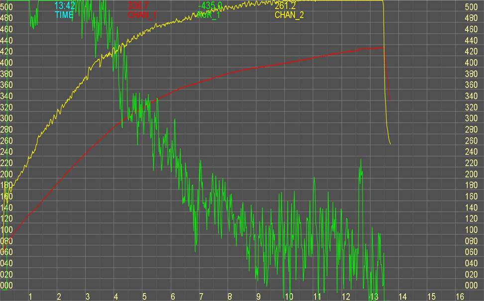
Attached is the results from last nights roast. I am currently only using the P (proportion term), I have the I and D terms zeroed out for now. The PID is controling ET, which is the yellow line. Still have some tweaking to do, but this is much better then the results I was getting a week ago. I was kind of stuck, getting a lot of overshoot/undershoot (much worse then in this graph) until I played with the gain term I had. In this version, gain is 50% (divide by 2), but I may lower it a little more. I have also tried to control fan speed with a SSR, and the 2nd output, but it is not working so far, I can't lower the fan speed. I am using 4hz as the output frequency, I may try to tweak this, and see what difference it makes. And the SSR I have is not a zero crossing one, not sure if this is a problem. I may also try adding a snubber on the SSR output. Randy
randytsuch attached the following image:
|
|
|
|
| JimG |
Posted on 08/30/2010 11:36 AM
|
|
1 1/2 Pounder Posts: 834 Joined: October 23, 2008 |
Nice! What kind of SSR are you using for the fan? Jim |
|
|
|
| randytsuch |
Posted on 08/30/2010 12:59 PM
|
|
1/2 Pounder Posts: 394 Joined: June 20, 2009 |
Quote JimG wrote: Nice! What kind of SSR are you using for the fan? Jim I bought a lot of 4 used Crydom SSR's a while back. I think they are D2440-10's. Way overkill for a fan, but I really bought them for my roaster and espresso machine. I will look for a smaller, one, without the "-10". "-10" means random turn on, instead of zero crossing. Randy |
|
|
|
| seedlings |
Posted on 08/30/2010 3:40 PM
|
 1 1/2 Pounder Posts: 4226 Joined: June 27, 2007 |
I've read and reread much of this thread, but still remain a little overwhelmed by the learning curve (my only experience is with eeprom in Fujitsu multiplexers). Would it be possible for someone to write a summary of what duties this controller does for a roaster right now, and also what it might be able to in the near future? I gather that it reads environment/heater temperature, and adjusts heat based on that TC input and programming. Separately it reads and records/displays bean temperature, but ET is not necessarily influenced by BT. Am I way off? CHAD Roaster: CoffeeAir II 2# DIY air roaster
Grinder: Vintage Grindmaster 500 Brewers: Vintage Cory DCU DCL, Aeropress, Press, Osaka Titanium pourover |
|
|
|
| randytsuch |
Posted on 08/30/2010 4:55 PM
|
|
1/2 Pounder Posts: 394 Joined: June 20, 2009 |
Quote seedlings wrote: I've read and reread much of this thread, but still remain a little overwhelmed by the learning curve (my only experience is with eeprom in Fujitsu multiplexers). Would it be possible for someone to write a summary of what duties this controller does for a roaster right now, and also what it might be able to in the near future? I gather that it reads environment/heater temperature, and adjusts heat based on that TC input and programming. Separately it reads and records/displays bean temperature, but ET is not necessarily influenced by BT. Am I way off? CHAD Chad There are a couple projects based on the TC4. Jim and Bill have a monitoring program, that displays and records temps for 2 channels, and rate of rise for 1 channel. I am working on a program, based on Jim and Bill's work. It is a PID, which controls ET. It maintains the functions of the monitoring program, so it will still record and monitor BT and ET, but all control is based on ET. My effort is a work in progress, that is going slowly, but it is starting to get there. All my work is based on using a Popcorn Pumper, which is my roaster. Right now, I am trying to make the program support multiple profiles, and then add a user interface with switches to allow selection of a profile, but I'm not a very good programmer, so it is slow going. I also still want to tweak my PID more, hopefully I can make the ET curve smoother. Randy |
|
|
|
| JimG |
Posted on 08/30/2010 10:57 PM
|
|
1 1/2 Pounder Posts: 834 Joined: October 23, 2008 |
Currently, the Bourbon software package is available for download and use. Along with the TC4 shield and an Arduino Duemilanove, it will do these strange and wonderful things: A. Standalone mode with 16 x 2 LCD 1. Display elapsed time 2. Display BT 3. Display ET 4. Display rate of rise (RoR) for BT B. When linked to a computer via USB connection 1. Log elapsed time, BT, RoR on BT, ET, and RoR on ET to a CSV file 2. Realtime plot of BT, ET, and RoR on BT 3. JPG capture of realtime plot by clicking mouse at any time 4. Rudimentary notations in log file by pressing a key The new version of the board (V3.00), along with the development version of the Bourbon code, also provides the ability to manually control an SSR using an external potentiometer. This has been tested on my Hottop for heater control, but no other roasters yet. The power output can selected at any whole number between 0% and 100% by turning the pot. The current value of the power output is displayed on the LCD. In the near future, the Bourbon application will also have the ability to read calibration data from EEPROM, and read a second potentiometer for fan control. That's about as far as I plan to take the Bourbon application. When done, it will support a nice standalone roast monitor (time, BT, RoR, and ET) that can optionally be used to control the heater and fan on a roaster by adding a couple of 100K panel-mounted potentiometers and appropriate SSR's. Randy's PID control software looks like it is coming along, too, but I won't make any commitments for him :-) There are many, many other applications that version 3.00 of the board could support, and there is an open source archive of the code written by Bill and me at http://code.googl...c4-shield/. I think an early version of Randy's PID code is posted there as well. If anyone is interested in adding to the code base, you'll find that much of the heavy lifting has been done already, and there are reasonably well-documented libraries available in the archive. Jim |
|
|
|
| bvwelch |
Posted on 08/31/2010 6:40 AM
|
 1 1/2 Pounder Posts: 1064 Joined: December 27, 2007 |
Hi CHAD, I like the above summaries as to what the software does now. My question is- what would you like it to do? If, for example, you preferred to use BT as the control input, instead of ET, that is possible. But we've found that using ET as the controlling input gives better results. |
|
|
|
| JETROASTER |
Posted on 08/31/2010 6:54 AM
|
 Administrator Posts: 1782 Joined: March 06, 2010 |
Quote bvwelch wrote: But we've found that using ET as the controlling input gives better results. Would that apply to both air and drum roasters? -Scott |
|
|
|
| Ringo |
Posted on 08/31/2010 6:55 AM
|
 Pounder  Posts: 474 Joined: January 14, 2010 |
All I can say is "Thank You". It is unbelievable what you have done for free. I am a red neck tinkerer so I have been sitting on the sidelines getting up my nerve to start my build. I am going to start gathering all the parts, this will be fun. I have a very basic understanding of electronics, all the part numbers sound like some kind of star trek code. You have explaned things very well so I am going for it. Dusting off my soldering iron, hope I can find it!
All you need in life is ignorance and confidence, and then success is sure. Mark Twain
|
|
|
|
| bvwelch |
Posted on 08/31/2010 8:20 AM
|
|
1 1/2 Pounder Posts: 1064 Joined: December 27, 2007 |
Hi Scott, I have no experience with drum roasting, yet. Someday I hope to build a sample roaster. |
|
|
|
| seedlings |
Posted on 08/31/2010 8:21 AM
|
|
1 1/2 Pounder Posts: 4226 Joined: June 27, 2007 |
Thank you guys for the entire project, and for the summary! Bill, since I don't know what's impossible... Ideally: 1)draw/program a curve for BT 2)Control ET to meet BT curve 3)Limit ET so temperature doesn't get too high or too low. Three would be the 'hard' part. As an example, I want to meet BT curve as closely as possible, but don't want ET to get above 550F, nor below 400F (once 400F BT is reached, of course). -OR- limit ET to be between BT+15F and BT+125F so that the roast doesn't stall or accelerate too quickly. Whew. That's all ;) CHAD Edited by seedlings on 08/31/2010 8:26 AM Roaster: CoffeeAir II 2# DIY air roaster
Grinder: Vintage Grindmaster 500 Brewers: Vintage Cory DCU DCL, Aeropress, Press, Osaka Titanium pourover |
|
|
|
| bvwelch |
Posted on 08/31/2010 8:24 AM
|
|
1 1/2 Pounder Posts: 1064 Joined: December 27, 2007 |
Welcome Ringo, let us know if we can help. I envy you guys who can weld and build roasters. I'm lucky that popcorn poppers and bread machines are fairly easy to modify. :-) |
|
|
|
| Ringo |
Posted on 08/31/2010 11:24 AM
|
|
Pounder Posts: 474 Joined: January 14, 2010 |
First Question The order WIKI said get a part number 493-1372-nd cap, it was sold out. I ordered a 493-1144-nd 10uf 100v elect VR radial. Will this one work? All you need in life is ignorance and confidence, and then success is sure. Mark Twain
|
|
|
|
| bvwelch |
Posted on 08/31/2010 7:17 PM
|
|
1 1/2 Pounder Posts: 1064 Joined: December 27, 2007 |
It may be OK - depends on how 'tall' it is and whether you care - if you plan to stack another 'shield' on top then it might be a problem. I found a 10uf tantalum in the junk box that worked good. If you can bend the leads that might work too. As far as I know you might get by with anything in the 4.7 to 50uf range so long as the voltage rating is met. If you end up needing a part we can help, or maybe a trip to the local Radio Shack. |
|
|
|
| rama |
Posted on 08/31/2010 8:53 PM
|
|
Newbie Posts: 49 Joined: April 07, 2010 |
Definitely interested in another board to try Randy's PID! All the changes to v3 sound like improvements, good job Jim. |
|
|
|
| JimG |
Posted on 08/31/2010 9:21 PM
|
|
1 1/2 Pounder Posts: 834 Joined: October 23, 2008 |
Bare PCB's (version 3.00) are now available here: http://www.mlgp-l...o-pcb.html Price is still $6.00 plus $2.00 for first class postage. The bill of materials is similar to the previous version, but not identical. I'll get this updated as soon as I can and post it on the googlecode site. Jim |
|
|
|
| rama |
Posted on 08/31/2010 10:33 PM
|
|
Newbie Posts: 49 Joined: April 07, 2010 |
Randy and others interested in Arduino based PID implementations, take a look at Adafruit's codebase: http://github.com...eflowduino |
|
|
|
| randytsuch |
Posted on 09/01/2010 2:13 PM
|
|
1/2 Pounder Posts: 394 Joined: June 20, 2009 |
Quote rama wrote: Randy and others interested in Arduino based PID implementations, take a look at Adafruit's codebase: http://github.com...eflowduino Thanks for the link, it's alway nice to see how someone else does it. I have a couple comments to those considering my PID program. I am using a 20x4 LCD, instead of the 16x2 LCD that the orginal software uses. The extra rows obviously allow for more information to be displayed, which is nice for the PID. It has been invaluable for me to debug my program, and I think the extra information would be nice for tuning the PID. I think you could get by with a 16x2, if you use a PC too, and then you can read the temp and RoR infomation from the PC screen, and use the LCD to display the PID information. At some point, I will change my LCD code to display the PID information on the first two lines. I am also adding 4 switches. Hopefully, this will let you pick a profile, from some number of profiles which are stored in memory. The problem with 4 switches is that they take up four IO pins, which are now in short supply. I am planning to use D0-D3 for these switches. I have already bought and mounted the switches, just have to wire them up to the IO pins, and then see if I can make a crude UI with them. Randy Edited by randytsuch on 09/01/2010 2:14 PM |
|
|
|
| JimG |
Posted on 09/01/2010 11:40 PM
|
|
1 1/2 Pounder Posts: 834 Joined: October 23, 2008 |
Hi, Randy - You might consider using an I2C port expander for the buttons? I'm doing some experimenting with the MCP23017 right now and hope to be able to use it to control an LCD and read some buttons. Something like a JeeLabs LCD Plug with buttons is what I have in mind. Jim |
|
|
|
| Dan |
Posted on 09/02/2010 8:05 AM
|
|
1 1/2 Pounder Posts: 1662 Joined: October 24, 2005 |
Randy, I don't care about logging, but a PID with stored profiles is exactly what I want. I've been thinking about selecting stored profiles using an Arduino, too. What I came up with is using one digit on the LCD to represent one of 10 stored profiles. Then, upon startup, you'd press a momentary switch (just one pin used) until you scrolled through the list to the profile you wanted to use. I suppose you could use letters and have 26 profiles, or even a few letters for a name or abbreviation. The profiles would be downloaded as tables via USB. For your use, here's a pin saving idea. Use two switches instead of four. When used as a digital input it gives you four profile selections. Here's how: Profile 1 = Sw1 0, Sw2 0 Profile 2 = Sw1 I, Sw2 0 Profile 3 = Sw1 0, Sw2 I Profile 4 = Sw1 I, Sw2 I 0=off I=on I don't know Arbuino code, but the logic would be: If Sw1=0 and Sw2=0, Then load Table 1, Else Next If Sw1=0 and Sw2=I, Then load Table 2, Else Next etc. Using this trick, four pins could get you 16 profiles, not 4! Edited by Dan on 09/02/2010 8:11 AM |
|
|
|

| Jump to Forum: |
Powered by PHP-Fusion Copyright © 2024 PHP-Fusion Inc
Released as free software without warranties under GNU Affero GPL v3
Designed with ♥ by NetriXHosted by skpacman