
Login

Shoutbox
You must login to post a message.
allenb
09/19/2024 11:19 AM
Firaollemecha 
allenb
09/15/2024 8:05 PM
JKnight
renatoa
09/15/2024 1:26 AM
JonnyPanic,  ?
?
?renatoa
09/13/2024 1:32 PM
Krush and jdspainhour,

renatoa
09/12/2024 1:06 AM
 , KnittyBrew
Forum Threads
Newest Threads
Hello from eastern PAHome Roaster Color M...
My Sight Glass FB Ro...
Coffee Crafters Flui...
First Roaster, DIY S...
Hottest Threads
| Skywalker roaster... | [386] |
| Skywalker Roasts | [102] |
| Using a TC4 with ... | [41] |
| Green coffee reviews | [10] |
In Memory Of Ginny

Donations
Latest Donations
dmccallum - 10.00
JackH - 25.00
snwcmpr - 10.00
Anonymous - 2.00
Anonymous - 5.00
dmccallum - 10.00
JackH - 25.00
snwcmpr - 10.00
Anonymous - 2.00
Anonymous - 5.00
Users Online
Guests Online: 4
Members Online: 0
Total Members: 8,498
Newest Member: Firaollemecha
Members Online: 0
Total Members: 8,498
Newest Member: Firaollemecha
View Thread
Who is here? 1 guest(s)
 4-channel TC meter and datalogger project
|
|
| mikeasr |
Posted on 09/22/2010 8:25 PM
|
|
Newbie  Posts: 11 Joined: September 06, 2010 |
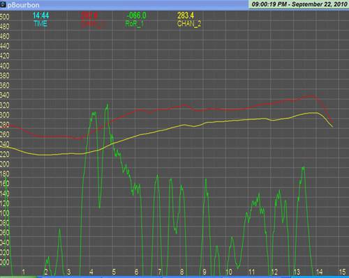
Thanks Jim, I'll give that a try. Here's the first (monitored) roast. Goal #1 complete....goal #2 is to get manual control of fan and heater....goal #3....PID control. My displayed temps are off. How do I correct? Mike
mikeasr attached the following image:
|
|
|
|
| milowebailey |
Posted on 09/22/2010 9:46 PM
|
 1/4 Pounder  Posts: 124 Joined: May 01, 2009 |
Quote randytsuch wrote: I thought about my fan issues yesterday, and decided against trying something with x10. I think it would have been a slick solution, but the problem with digital dimmers is that you get a limited number of discrete steps. I am used to using a analog dimmer, where you have "infinite" steps. In practice, a x10 digital dimmer may have fine enough resolution to work, but I don't want to spend the money to find out. This leads me to Bill's suggestion to rectify my AC, and then use a mosfet controlled by one of the PWM outputs to control fan speed. This will work for me, and I am planning to do this to get my setup working, but it is not a very universal solution. It works for anyone with a P1 or Pumper, but not many others. In the future, I may try for a different, more universal solution. I am planning to use an Arduino to replace my PID on my espresso machine, and for that application, will need to figure out how to control the pump pressure. I do it now manually with a light dimmer, so it is very similar to this problem, and I can't (at least I don't think I can) feed that pump DC. Randy Randy A triac will work better. Here is a circuit that will work with the arduino. You will need to sense the zero crossing of the AC line and then trigger the triac with an output. This would give you analog control. The later hottops use this technology to contol the fan and, I think the heater. http://www.andrew...age_id=445 Another meathod here http://www.techli...ontrol.htm another here https://www.onsem...8011-D.PDF Edited by milowebailey on 09/22/2010 10:21 PM |
|
|
|
| JimG |
Posted on 09/22/2010 10:22 PM
|
|
1 1/2 Pounder  Posts: 834 Joined: October 23, 2008 |
Quote mikeasr wrote: My displayed temps are off. How do I correct? Mike - Two things to check: 1. Confirm that you are using type K thermocouples. 2. Check the output from the ambient temperature sensor. The easiest way to check the ambient temp sensor is to unplug the thermocouples and observe the output temperatures. With open inputs, the TC4 will report ambient temperature for both channels. The "official" way to check the ambient sensor is to view the serial data stream coming from the board, using the Arduino IDE's serial monitor or the console window of the Processing IDE. The second value on each line of output is the ambient sensor reading. Since your readings seem to be around 80F low, I suspect that the ambient sensor is not working right. Jim |
|
|
|
| randytsuch |
Posted on 09/22/2010 11:23 PM
|
 1/2 Pounder  Posts: 394 Joined: June 20, 2009 |
Quote milowebailey wrote: Randy A triac will work better. Here is a circuit that will work with the arduino. You will need to sense the zero crossing of the AC line and then trigger the triac with an output. This would give you analog control. The later hottops use this technology to contol the fan and, I think the heater. http://www.andrew...age_id=445 Another meathod here http://www.techli...ontrol.htm another here https://www.onsem...8011-D.PDF Thanks for the links, and the advice. I may use them in the future, but later in this thread Bill pointed out that I could drive my Popcorn Pumper fan motor with DC. So, I plan to rectify my AC, and then I bought a DC SSR to control the power to the fan. Since it is DC, I expect to have better control over on/off time than I had with a AC SSR. At some point, I want to control a espresso machine pump, and will probably study your links in more detail then. Randy |
|
|
|
| seedlings |
Posted on 09/23/2010 8:23 AM
|
 1 1/2 Pounder Posts: 4226 Joined: June 27, 2007 |
This is a Variable Voltage Regulator for DC: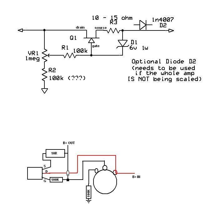 I use it in tube guitar amps to lower the rail voltage from 400+ volts down to about 40V and everywhere in between. If R2 is 10% of the pot, so your lower voltage limit will be 10% of your supply voltage. You won't need D2. Q2 is NTE2377, which is kind of expensive, but I robbed a mosfet from a defunct cpu power supply. Other known workers are MPT6N60E, IRF740B, STF9NK60ZD. CHAD Edited by seedlings on 09/23/2010 8:24 AM Roaster: CoffeeAir II 2# DIY air roaster
Grinder: Vintage Grindmaster 500 Brewers: Vintage Cory DCU DCL, Aeropress, Press, Osaka Titanium pourover |
|
|
|
| randytsuch |
Posted on 09/23/2010 9:10 AM
|
|
1/2 Pounder Posts: 394 Joined: June 20, 2009 |
Quote seedlings wrote: This is a Variable Voltage Regulator for DC: I use it in tube guitar amps to lower the rail voltage from 400+ volts down to about 40V and everywhere in between. If R2 is 10% of the pot, so your lower voltage limit will be 10% of your supply voltage. You won't need D2. Q2 is NTE2377, which is kind of expensive, but I robbed a mosfet from a defunct cpu power supply. Other known workers are MPT6N60E, IRF740B, STF9NK60ZD. CHAD Thanks for the circuit. I used an SSR so that I can connect it to a Arduino PWM output, and hopefully I can vary the fan speed so that it won't effect my roasts. I did conclude that with a AC SSR, the fan speed was not constant, and this seems to negatively impact the roasts, it would slow my profiles down. Randy |
|
|
|
| JimG |
Posted on 09/23/2010 4:46 PM
|
|
1 1/2 Pounder Posts: 834 Joined: October 23, 2008 |
Quote milowebailey wrote: Here is a circuit that will work with the arduino. You will need to sense the zero crossing of the AC line and then trigger the triac with an output. Version 3.00 of the TC4 shield added a pin header labeled "IO3." Among other things, this port can be used to sense an external signal and then generate an interrupt. It is tied to one of the ATmega's interrupt pins. This tidbit of information might help anyone who decides to pursue zero-cross detection per the links that "milo" provided. Jim |
|
|
|
| JimG |
Posted on 09/26/2010 6:44 PM
|
|
1 1/2 Pounder Posts: 834 Joined: October 23, 2008 |
I've been playing around with LCD displays and pushbuttons lately. The result is a beta version of an I2C interface board. On the interface board are mounted four pushbuttons, a 16-pin header for directly connecting a typical 16 x 2 LCD, and an RJ-11 socket. The idea for this came from JeeLabs' LCD Plug. To that basic idea, I added pushbuttons and the RJ-11 socket. I had to use a 16-bit port expander instead of 8-bit, though, since I added the buttons. The interface board connects via 4 conductor phone cable to the I2C header on Version 3.00 of the TC4 shield. I had a couple of prototypes built by BatchPCB and have been testing them this weekend. The interface board works fine at the end of a 30"length of phone cable (I haven't tried going any longer). I'm not sure what I'll do with 4 buttons. I modified the development version of the Bourbon code to watch for button presses. Right now, I've got it set up to reset the elapsed time to zero upon any button press. I am using my TC4 as a standalone roast monitor and manual heater controller for my Hottop, and being able to reset the timer is pretty handy. If there's interest, I can post photos and other information. Jim |
|
|
|
| rama |
Posted on 09/26/2010 7:04 PM
|
|
Newbie Posts: 49 Joined: April 07, 2010 |
I added a bit of code to the Processing bits to include a RoR average (currently set to a 10 second window). Seems to help me a lot when the RoR values are erratic. Next I hope to add visual flags on certain key presses, ex: "f" would flag beginning of first crack on the graphs somehow. Jim, happy to roll this stuff back if you (or others) are interested. I'm 'altbit' if its easier to make me a committer. --rama |
|
|
|
| randytsuch |
Posted on 09/26/2010 9:55 PM
|
|
1/2 Pounder Posts: 394 Joined: June 20, 2009 |
Quote JimG wrote: I've been playing around with LCD displays and pushbuttons lately. The result is a beta version of an I2C interface board. On the interface board are mounted four pushbuttons, a 16-pin header for directly connecting a typical 16 x 2 LCD, and an RJ-11 socket. The idea for this came from JeeLabs' LCD Plug. To that basic idea, I added pushbuttons and the RJ-11 socket. I had to use a 16-bit port expander instead of 8-bit, though, since I added the buttons. The interface board connects via 4 conductor phone cable to the I2C header on Version 3.00 of the TC4 shield. I had a couple of prototypes built by BatchPCB and have been testing them this weekend. The interface board works fine at the end of a 30"length of phone cable (I haven't tried going any longer). I'm not sure what I'll do with 4 buttons. I modified the development version of the Bourbon code to watch for button presses. Right now, I've got it set up to reset the elapsed time to zero upon any button press. I am using my TC4 as a standalone roast monitor and manual heater controller for my Hottop, and being able to reset the timer is pretty handy. If there's interest, I can post photos and other information. Jim Jim I'm interested. I just bought an old alpenrost to use an an arduino project, I want to play with a drum type roaster. The alpenroast needs a four output discretes, and I have four left, but I was looking at adding an I2C 8 bit port expander to do it. If you already have this, I would like to see how you did it. Randy |
|
|
|
| JimG |
Posted on 09/27/2010 7:38 AM
|
|
1 1/2 Pounder Posts: 834 Joined: October 23, 2008 |
Quote rama wrote: I added a bit of code to the Processing bits to include a RoR average (currently set to a 10 second window). Seems to help me a lot when the RoR values are erratic. Hi, Rama - This sounds like a good solution. But I want to let you (and others) know that there is also a provision in the most recent aBourbon.pde code to adjust the level of filtering of RoR. This adjustment is made before the RoR values are sent to the Arduino's serial output. The development version of aBourbon.pde uses fairly heavy digital filtering on BT readings before calculating RoR. You may want to download and install the most recent aBourbon.pde from the googlecode site and give it a try to see if it solves the problem. Click the following link to see the current code. The value for RISE_FILTER can be altered as needed. The useful range is probably between 70 and 90-ish. http://code.googl...ourbon.pde Jim |
|
|
|
| JimG |
Posted on 09/28/2010 7:14 AM
|
|
1 1/2 Pounder Posts: 834 Joined: October 23, 2008 |
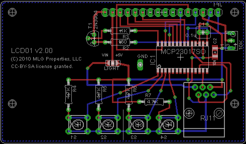
Quote randytsuch wrote: Jim I'm interested. I just bought an old alpenrost to use an an arduino project, I want to play with a drum type roaster. The alpenroast needs a four output discretes, and I have four left, but I was looking at adding an I2C 8 bit port expander to do it. If you already have this, I would like to see how you did it. I'll get some pictures posted soon. Here's an image of the board layout: EDIT: OK, I give up. I guess I'm not smart enough to attach an image. EDIT: Links to PDF's showing the board and schematic: http://code.googl...00.sch.pdf http://code.googl...00.brd.pdf Jim Edited by JimG on 09/28/2010 8:26 AM |
|
|
|
| randytsuch |
Posted on 09/28/2010 2:12 PM
|
|
1/2 Pounder Posts: 394 Joined: June 20, 2009 |
Quote JimG wrote: I'll get some pictures posted soon. Here's an image of the board layout: EDIT: OK, I give up. I guess I'm not smart enough to attach an image. EDIT: Links to PDF's showing the board and schematic: http://code.googl...00.sch.pdf http://code.googl...00.brd.pdf Jim Some threads support attaching pics, and some don't, and I have no idea why? Thanks for the info, I also noticed it comes in a dip package, so it would be easy for me to add to my setup. Randy |
|
|
|
| seedlings |
Posted on 09/28/2010 2:43 PM
|
|
1 1/2 Pounder Posts: 4226 Joined: June 27, 2007 |
Jim, could you email me one of yon pictures? seedlingscoffee@gmail.com CHAD Roaster: CoffeeAir II 2# DIY air roaster
Grinder: Vintage Grindmaster 500 Brewers: Vintage Cory DCU DCL, Aeropress, Press, Osaka Titanium pourover |
|
|
|
| JimG |
Posted on 09/28/2010 7:26 PM
|
|
1 1/2 Pounder Posts: 834 Joined: October 23, 2008 |
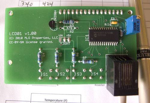
LCD
JimG attached the following image:
Edited by seedlings on 09/28/2010 7:46 PM |
|
|
|
| JimG |
Posted on 09/28/2010 8:57 PM
|
|
1 1/2 Pounder Posts: 834 Joined: October 23, 2008 |
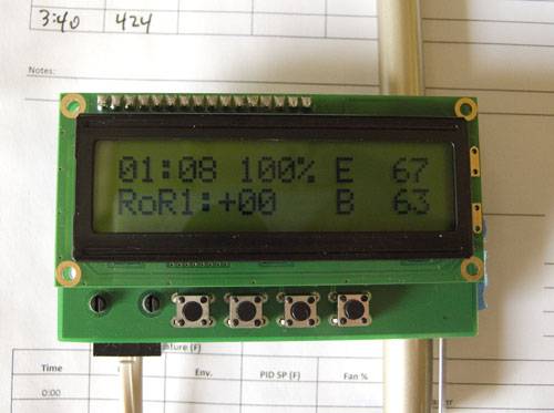
Front view of a 16 x 2 LCD attached to the new LCD expansion board. Note the 4-conductor telephone cord used to connect the LCD to the TC4 board.
JimG attached the following image:
|
|
|
|
| JimG |
Posted on 09/28/2010 8:59 PM
|
|
1 1/2 Pounder Posts: 834 Joined: October 23, 2008 |
Rear view of the LCD expansion board. This LCD does not have a backlight, so there is an empty spot where a resistor would be used to control the backlight brightness. (The backlight can be turned on and off by the Arduino).
JimG attached the following image:
|
|
|
|
| JimG |
Posted on 09/28/2010 9:01 PM
|
|
1 1/2 Pounder Posts: 834 Joined: October 23, 2008 |
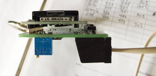
Edge view showing the connection between the LCD and the expansion board. I mounted this LCD with a little extra space, but normally it would be nearly flush.
JimG attached the following image:
|
|
|
|
| JimG |
Posted on 09/28/2010 9:05 PM
|
|
1 1/2 Pounder Posts: 834 Joined: October 23, 2008 |
Quote seedlings wrote: Jim, could you email me one of yon pictures? seedlingscoffee@gmail.com DOH! Chad pointed out that when you hit the "preview post" button, the picture is wiped out. Yup, that's what happens  Jim |
|
|
|
| JimG |
Posted on 09/28/2010 9:20 PM
|
|
1 1/2 Pounder Posts: 834 Joined: October 23, 2008 |
New release of the aBourbon.pde code is on the googlecode site: http://tc4-shield...ourbon.zip This release optionally reads calibration information from the EEPROM chip on the V3.00 boards, and also optionally supports an I2C LCD expansion board. It still supports the original 8-pin LCD header on the V3.00 boards. aBourbon can be used as a standalone roast monitor that shows BT, RoR, ET, and elapsed time on a 16 x 2 LCD. The LCD can be attached either using the I2C interface, or using the LCD header built into the V3.00 TC4 boards. Since aBourbon sends a stream of output over the serial port, you can connect it to your computer and get real time traces of BT, RoR, and ET using a Processing sketch (pBourbon, for example). An attached LCD is not needed in this instance. Jim |
|
|
|
| bvwelch |
Posted on 09/28/2010 9:21 PM
|
 1 1/2 Pounder Posts: 1064 Joined: December 27, 2007 |
Good looking LCD solution and buttons too! |
|
|
|
| randytsuch |
Posted on 09/29/2010 6:16 PM
|
|
1/2 Pounder Posts: 394 Joined: June 20, 2009 |
Jim Nice I2C LCD interface board. I am planning to "borrow" some of your eerom and 23017 code for the next set of enhancements to Kona. One minor suggestion for the LCD board, you could bring the unused 23017 IO pins to holes, so it would be easy to connect them to something else. Randy |
|
|
|
| JimG |
Posted on 09/29/2010 11:12 PM
|
|
1 1/2 Pounder Posts: 834 Joined: October 23, 2008 |
Quote randytsuch wrote: I am planning to "borrow" some of your eerom and 23017 code for the next set of enhancements to Kona. Glad to hear it! Be sure and carry forward the acknowledgments to JeeLabs and the Arduino guys/gals for the I2C LCD code if you use it. Quote randytsuch wrote: One minor suggestion for the LCD board, you could bring the unused 23017 IO pins to holes, so it would be easy to connect them to something else. Good idea. Thanks. Jim |
|
|
|
| randytsuch |
Posted on 09/30/2010 12:09 AM
|
|
1/2 Pounder Posts: 394 Joined: June 20, 2009 |
So I think I am really close to having a new version of Kona ready. I think I just fixed a bug in the ambient temp sent over the serial port, and I am tweaking the display a little for manual roasts. I decided you need to display ror if you are changing ror  I have a question for any prospective users. I want to add something like Jim is doing, an I2C port expander. I am thinking about adding one more key, so I can change the keys to LEFT, RIGHT, UP, DOWN and SELECT, and then read the keys through the port expander. I also want to add support for an EEROM, and start storing the profiles in EEROM. This will allow future support for easier updating of profiles, and also saving all the user specific information in eerom. This means you either would need to add EEROM to your setup, or use the newer version TC4 with EEROM on it. You would also need to add the port expander chip. Both EEROM and the port expander are available in dip packages, so it would be fairly easy to add in a proto shield. I will probably just wire them up on a protoboard, and connect them to my Arduino. Wondering if anybody objects to this plan. I would still put out this version with the current button implementation, but fairly soon (as soon as I get the parts and them implement it), there would be another version which supports the port expander for reading buttons. Randy |
|
|
|
| SteveN |
Posted on 09/30/2010 9:10 AM
|
 1/4 Pounder Posts: 127 Joined: March 16, 2010 |
I can't say that I object to anything yet. I'm still trying to wrap my head around all of the functionality that you guys have put together already. I hope to have my board up and running in a couple weeks (I'm still waiting on some parts to come in). I likely won't be using an LCD as everything will be going to the PC. Is that right or does the RoR need to go to the LCD? |
|
|
|

| Jump to Forum: |
Powered by PHP-Fusion Copyright © 2024 PHP-Fusion Inc
Released as free software without warranties under GNU Affero GPL v3
Designed with ♥ by NetriXHosted by skpacman