
Login

Shoutbox
You must login to post a message.
renatoa
07/26/2024 3:49 PM
Bill grubbe and Jk, 
allenb
07/26/2024 5:15 AM
Spiderkw Welcome to HRO!

renatoa
07/24/2024 8:31 AM
ramiroflores and John123,

 ?
?
?renatoa
07/21/2024 1:18 AM
 , Luislobo
renatoa
07/19/2024 11:28 AM
Koepea,
Forum Threads
Newest Threads
Skywalker roaster modsBackground Roast Iss...
Hello from Arkansas
TC4ESP
Green coffee reviews
Hottest Threads
| Skywalker roaster... | [375] |
| TC4ESP | [115] |
| War on Farmers by... | [47] |
| Adventures in flu... | [26] |
| Hello! (soon) Roa... | [17] |
In Memory Of Ginny

Donations
Latest Donations
dmccallum - 10.00
JackH - 25.00
snwcmpr - 10.00
Anonymous - 2.00
Anonymous - 5.00
dmccallum - 10.00
JackH - 25.00
snwcmpr - 10.00
Anonymous - 2.00
Anonymous - 5.00
Users Online
Guests Online: 3
Members Online: 0
Total Members: 8,393
Newest Member: Bill grubbe
Members Online: 0
Total Members: 8,393
Newest Member: Bill grubbe
View Thread
Who is here? 1 guest(s)
 Heat Gun...Max Capability?
|
|
| JETROASTER |
Posted on 03/26/2011 6:48 AM
|
 Administrator Posts: 1780 Joined: March 06, 2010 |
Thanks!! Here's a breakdown. I'll get some other info up after my flight. -Scott
JETROASTER attached the following image:

|
|
|
|
| JETROASTER |
Posted on 03/26/2011 3:44 PM
|
|
Administrator Posts: 1780 Joined: March 06, 2010 |
The Flux Capacitor breakdown; Starting from the left. 1) Yoke; A 1-1/2" lavatory drain...tail cut off, and notched to accommodate the cross pattern of the heat element. This piece passes thru all the components, acts as the central yoke, as well as the hot air inlet. 2) Lower RC; The lid of a cocktail shaker, inverted,with the strainer knocked out. In the picture, part of the neck is cut away. That cut is not needed, and impeded a good temp reading at that point. So, this piece needs no cutting, the strainer gets knocked out, and 1 hole drilled to accommodate a thermometer. The strainer will become the distributor/perf. Spikes are optional! 3) The Collar; This piece is the upper lid from a smaller cocktail shaker, with a 1-3/4" cutout thru the center. It serves as a bushing between the upper furnace housing and the lower RC, providing greater stability as they get tightened together.(It's a giant washer) 4) Upper Furnace Housing ; Once again, the lid of a jumbo cocktail shaker, with the strainer knocked out. (the welds popped apart with 1 hit) 5) Heat Liner; A scavenged travel mug. Plastic liner removed, and the bottom knocked out. The cheap ones have a plastic base that pops right out...leaving a 1/8" flange....perfect to be captured by the anchor nut, and secure all 6 components together...just like installing a sink drain. There are about a dozen 1/2" cuts throughout the heat liner.(thin dremel wheel) These provide some additional cooling for the liner. There are also 2, 1/32" holes drilled opposite each other, near the bottom of the liner. These serve as anchor points for the heat coil. 6) Anchor Nut; The very same nut that would be used for installing the drain into a sink . At the outer flange of the nut, 2 notches are filed into the flange, opposite each other, to provide a grip for tightening . 7) Heating Element, about 5" of nichrome removed, stretched and re-wrapped. |
|
|
|
| JETROASTER |
Posted on 03/26/2011 11:04 PM
|
|
Administrator Posts: 1780 Joined: March 06, 2010 |
[video]http://www.youtube.com/ watch?v=ZevHcnygJbo[/video] |
|
|
|
| JETROASTER |
Posted on 04/14/2011 4:49 PM
|
|
Administrator Posts: 1780 Joined: March 06, 2010 |
One more shot before moving onto the blower section. Does any of this make sense? -Scott
JETROASTER attached the following image:

|
|
|
|
| greencardigan |
Posted on 04/14/2011 5:52 PM
|
 1 1/2 Pounder  Posts: 1185 Joined: November 21, 2010 |
Yep, mostly makes sense to me. I'm just not sure how the anchor nut is placed. Does it go up inside the element liner? Or around the element liner? |
|
|
|
| JETROASTER |
Posted on 04/14/2011 7:00 PM
|
|
Administrator Posts: 1780 Joined: March 06, 2010 |
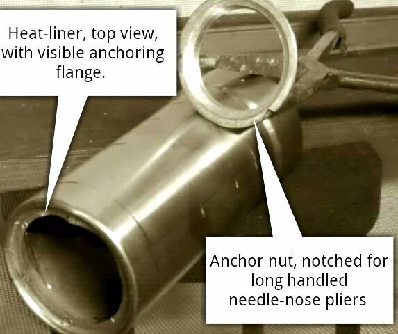
Quote greencardigan wrote: I'm just not sure how the anchor nut is placed. Does it go up inside the element liner? Or around the element liner? All the way up inside...prior to installing the heat element. I used long-handled needle-nose pliers to tighten the nut. -Scott
JETROASTER attached the following image:
|
|
|
|
| JETROASTER |
Posted on 04/21/2011 3:45 PM
|
|
Administrator Posts: 1780 Joined: March 06, 2010 |
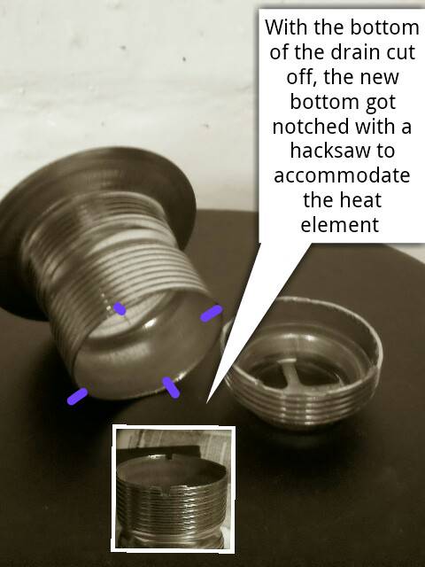
Here's a shot of the drain fitting as it became the yoke. 1 cut to remove the bottom, then 4 small notches with a hacksaw or file. ...Just enough to keep the heat element from shifting around. I hope ths part makes sense...I'm moving on to the blower. -Scott
JETROASTER attached the following image:
|
|
|
|
| JETROASTER |
Posted on 04/22/2011 10:51 AM
|
|
Administrator Posts: 1780 Joined: March 06, 2010 |
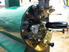
This is the top down view into the blower housing. 1)Barrier blocks (2ea.) One on each side of the housing, positioned just above the blower. These serve as electrical junction blocks, and anchor the blower in place. 2) Blower. 3", single-stage, flow-thru. 4 amps. ( the cross-bar over the blower will be edited out) 3) Electrical connectors. 1/2", 45?, (2ea). One for the blower, one for heat. I drilled the holes with a step-bit. 4) Wiring to the heat coil. On the left, you can see the pressure gauge. Next, it will be disassembled, edited, and put back together. The 3" blower is harder to track down than I thought. On the Open-Source thread, I'll include a description of some handvacs that use this blower .....they're out there. ( I can order them in cases of 6) -Scott
JETROASTER attached the following image:

|
|
|
|
| JETROASTER |
Posted on 06/08/2011 10:45 AM
|
|
Administrator Posts: 1780 Joined: March 06, 2010 |
The Update; The MH-1 is at it's new home. I ran 2 new circuits to deal with it. I removed the exhaust restrictor. It was clogging with chaff, and it just wasn't needed. I still need a proper exhaust out of the building, but time is always the problem. With warm weather here, it will do full-city in 10 minutes. The blower runs at 75% to start the roast, then down to about 60% at the end. I start with 8" pressure, and end with 6.25" to maintain the same fluidization.....more dramatic than I expected. It has zero heat control. I unplug the heat for cool down. The natural profile is very nice, but I can keep the blower speed up to stretch the load. Inlet temp seems to be 600dg, But I don't have a good direct reading. I've started prepping components for the HRO version! Thanks all for the tips and expertise. -Scott
JETROASTER attached the following image:

|
|
|
|
| seedlings |
Posted on 06/08/2011 3:16 PM
|
 1 1/2 Pounder Posts: 4226 Joined: June 27, 2007 |
Well done, Scott! What batch size does it like? CHAD Roaster: CoffeeAir II 2# DIY air roaster
Grinder: Vintage Grindmaster 500 Brewers: Vintage Cory DCU DCL, Aeropress, Press, Osaka Titanium pourover |
|
|
|
| JETROASTER |
Posted on 06/09/2011 8:44 AM
|
|
Administrator Posts: 1780 Joined: March 06, 2010 |
Thanks! So far I've been doing #1. I think #1.25 will work as well. I'll be installing a small spherical baffle just above the plume. I get a few renegade beans that escape. Once that's done, I could probably handle #1.5.....until winter comes. -Scott |
|
|
|
| JETROASTER |
Posted on 06/09/2011 10:23 AM
|
|
Administrator Posts: 1780 Joined: March 06, 2010 |
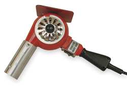
....Trying to figure this thing out. It says 3 wire plug. It also says '7amps @ 220'. Is it 220v or did someone slip me decaf? Thanks, -Scott http://www.graing...Pid=search
JETROASTER attached the following image:
|
|
|
|
| seedlings |
Posted on 06/09/2011 11:35 AM
|
|
1 1/2 Pounder Posts: 4226 Joined: June 27, 2007 |
http://masterappl...101102.pdf Page 4... has a different type plug for 220V? CHAD Edited by seedlings on 06/09/2011 11:35 AM Roaster: CoffeeAir II 2# DIY air roaster
Grinder: Vintage Grindmaster 500 Brewers: Vintage Cory DCU DCL, Aeropress, Press, Osaka Titanium pourover |
|
|
|
| JETROASTER |
Posted on 06/14/2011 11:35 AM
|
|
Administrator Posts: 1780 Joined: March 06, 2010 |
It looks like there are some assorted plug adaptors, but I still don't understand 220v with only 3 wires....at least not so as to make code. It's not anything I need right away, it just seemed odd. -Scott |
|
|
|
| Unta |
Posted on 06/14/2011 12:27 PM
|
 1 1/2 Pounder Posts: 788 Joined: January 26, 2010 |
When you say " 3-wire" 220v line, I would assume that you have 2 insulated copper wires and 1 bare copper wire. A "4-wire" 220v line would have 3 insulated copper conductors and 1 bare copper conductor. In a 3-wire 220v line, the two insulated wires each carry power to the appliance. These should be coloured black and red. This type of wire would be used to power for example an electric water heater. Because a 220v load does not need a neutral (white) wire to work, only 2 conductor wires are used with this application. A 4-wire 220v line is used for appliances such as stoves and clothes dryers. A 4-wire line has 2 insulated power wires (red and black), one neutral wire (white) and a bare ground wire. An appliance such as a clothes dryer actually has a mix of 220v and 110v circuits. Although the 220v circuit doesn't need a neutral wire to work, the 110v circuit does need the neutral (white) wire. This is why on some appliances a "3-wire" is all that's needed and for other appliances a "4-wire" is required. As far as converting this arrangement, a new "4-wire" should be installed from the panel replacing the "3-wire" arrangment. Consulting a licensed electrician for this highly recommended. As copied from do it your self .com's forumns Its more than you asked for, but I thought it was good over all answer . By no means do I think you can't handle it scott, i just verbatim copied it for everyone's education, especially mine..  ... ...Cheers! Edited by Unta on 06/14/2011 12:30 PM Sean Harrington
educate. |
|
|
|
| JETROASTER |
Posted on 06/14/2011 12:35 PM
|
|
Administrator Posts: 1780 Joined: March 06, 2010 |
Yeah, that's my understanding of it. That's why I was surprised. Maybe this thing is for markets outside the U.S. Anyway....good to see you back around!! Thanks,Scott |
|
|
|
| oldgearhead |
Posted on 06/14/2011 5:30 PM
|
 1 1/2 Pounder Posts: 1128 Joined: February 10, 2011 |
I think you will find that in the USA the neutral (white) and ground (bare) are connected together at the main distribution box. Therefore, they are at the same potential. Most large USA appliances use 120 VAC (white-to-black, or white-to-red) for control and signal lights and 220 (red-to-black) for heating or large motors..220 VAC in the USA may be either 3 or 4 wire. 4-wire simply includes both a neutral and ground wire. Edited by oldgearhead on 06/14/2011 5:35 PM No oil on my beans...
|
|
|
|
| JETROASTER |
Posted on 06/15/2011 4:30 PM
|
|
Administrator Posts: 1780 Joined: March 06, 2010 |
Thanks folks. That whole thing about common and ground still confuses me, but I'll get through it !! This version of the MH-1 has been dubbed "Spike" . Spike will be going to "Burning Man" in August. ....I'm not going, but Spike is. So, I installed a baffle in the RC to stop runaway beans, and I'll be replacing one sight-glass that did not hold up as advertised. It will get used as much as possible before the trip, that should work out any remaining bugs. I'll post a map of the location. If anyone has plans of attending, my friend Vinny will be cranking out the beans. -Scott
JETROASTER attached the following image:

|
|
|
|
| Unta |
Posted on 06/15/2011 7:16 PM
|
|
1 1/2 Pounder Posts: 788 Joined: January 26, 2010 |
Thats fantastic, should be a hit in the desert. Glad to have a little time to play again, hopefully more on the way... Cheers! Sean Harrington
educate. |
|
|
|
| JETROASTER |
Posted on 06/16/2011 8:29 AM
|
|
Administrator Posts: 1780 Joined: March 06, 2010 |
...I saw a couple questions on some other threads . Rather than schmuckin' up all the threads, I'll do it here. One was about cooling in the RC (Allen) I did a 2.5 minute cool-down to 150F this AM. This thing has very little thermal mass. Another question was about finding a cocktail shaker for an RC. (Green Cardigan) ...the link is on this thread... http://forum.home...ad_id=2110 The diameter at the base is 5" This vessel is good for 1#. I tried 1.25# ...even with the baffle, I had beans trying to escape by the time I got to 1st C. I shot video of a casual cool-down (3 min). I'll post that at some point. -Scott |
|
|
|
| JETROASTER |
Posted on 06/16/2011 2:49 PM
|
|
Administrator Posts: 1780 Joined: March 06, 2010 |
....And a little cool-down video. Warning!!!! This is a bit boring!!!! It's 3 minutes of gauges dropping, shot with a droid, with little caffiene in my system.....you were warned. Very little variation between the gauges...that's during the roast as well. That is not the case with the larger roaster. I guess size matters. -Scott [video]http://www.youtube.com/watch?feature=player_profilepage&v=cQg6Fv8Uh3U[/video] |
|
|
|
| allenb |
Posted on 06/16/2011 8:27 PM
|
 Administrator Posts: 3869 Joined: February 23, 2010 |
Quote freshbeans wrote: ....And a little cool-down video. Warning!!!! This is a bit boring!!!! It's 3 minutes of gauges dropping, shot with a droid, with little caffiene in my system.....you were warned. Very little variation between the gauges...that's during the roast as well. That is not the case with the larger roaster. I guess size matters. -Scott [video]http://www.youtube.com/watch?feature=player_profilepage&v=cQg6Fv8Uh3U[/video] Scott, no roaster video is boring! Looking good. In your previous post you mentioned cooling down to 150 in 2 1/2 min. I'm sure this is plenty fast enough to not cause baked flavors to appear. It seems the thermal mass of this roaster is low enough to allow in-chamber cooling. Brad had asked what the max time for cooling should be. I'm not aware of a study that has quantified this but maybe there is such a study. I'd like to hear more about this also. I've always heard the most important part of the cool down is getting the first 100 degrees very quickly but also to have it down to 200 F in no more than 2 1/2 min. Allen 1/2 lb and 1 lb drum, Siemens Sirocco fluidbed, presspot, chemex, cajun biggin brewer from the backwoods of Louisiana
|
|
|
|
| JETROASTER |
Posted on 06/16/2011 10:00 PM
|
|
Administrator Posts: 1780 Joined: March 06, 2010 |
......And also,there was a thing Dan had taken note of somewhere ....that a quick roast cycle should get a more protracted cooling cycle. I personally feel that a quick roast also needs a longer rest. I guess I just believed that a quicker cooling was always better . Now, I guess I'm not as sure. The variables are killing me. I may need to do some tests roasts, then send them to someone else for tasting. -Scott |
|
|
|
| JETROASTER |
Posted on 07/20/2011 10:31 AM
|
|
Administrator Posts: 1780 Joined: March 06, 2010 |
Well, I saw a couple threads talking about bean removal. OGH sucked 'em right out...very nice. GC was thinking about just pressurizing them out, so I figured I'd give it a shot. I had to alter the baffle inside the MH-1. It was mounted up high in the RC to prevent beans from flying up and out. It was also preventing me from inserting a tube to remove the beans. So, I re-installed the baffle on a spring, vs. the rigid bolt I used previously. The baffle still prevents rogue beans from escaping, but allows a 1.25" tube to be inserted. Inserting the tube alone does not get the job done... Pressure has to be created to force the beans out. Simply obstructing the rest of exhaust port by hand (literally) did the trick. So here's a little video featuring mostly my elbow. In the background you'll notice beans leaving the roaster. I used green just to make it challenging. Only 2 stragglers were left behind. -Cheers , -Scott [video]http://www.youtube.com/watch?feature=player_profilepage&v=bwqfxv3-qtE[/video]
JETROASTER attached the following image:

Edited by JETROASTER on 07/20/2011 10:37 AM |
|
|
|
| greencardigan |
Posted on 07/20/2011 9:43 PM
|
|
1 1/2 Pounder Posts: 1185 Joined: November 21, 2010 |
Excellent! I tried the same thing yesterday and also found that I had to seal off the top of the roast chamber. I had trouble catching the beans coming out the end of the tube. How are you dissipating the air? I had beans spraying out everywhere and getting blown out of my collection container. |
|
|
|

| Jump to Forum: |
Powered by PHP-Fusion Copyright © 2024 PHP-Fusion Inc
Released as free software without warranties under GNU Affero GPL v3
Designed with ♥ by NetriXHosted by skpacman