
Login

Shoutbox
You must login to post a message.
renatoa
07/26/2024 3:49 PM
Bill grubbe and Jk, 
allenb
07/26/2024 5:15 AM
Spiderkw Welcome to HRO!

renatoa
07/24/2024 8:31 AM
ramiroflores and John123,

 ?
?
?renatoa
07/21/2024 1:18 AM
 , Luislobo
renatoa
07/19/2024 11:28 AM
Koepea,
Forum Threads
Newest Threads
Skywalker roaster modsBackground Roast Iss...
Hello from Arkansas
TC4ESP
Green coffee reviews
Hottest Threads
| Skywalker roaster... | [375] |
| TC4ESP | [115] |
| War on Farmers by... | [47] |
| Adventures in flu... | [26] |
| Hello! (soon) Roa... | [17] |
In Memory Of Ginny

Donations
Latest Donations
dmccallum - 10.00
JackH - 25.00
snwcmpr - 10.00
Anonymous - 2.00
Anonymous - 5.00
dmccallum - 10.00
JackH - 25.00
snwcmpr - 10.00
Anonymous - 2.00
Anonymous - 5.00
Users Online
Guests Online: 4
Members Online: 0
Total Members: 8,393
Newest Member: Bill grubbe
Members Online: 0
Total Members: 8,393
Newest Member: Bill grubbe
View Thread
Who is here? 1 guest(s)
 TC4 - Coding and tech issues
|
|
| JimG |
Posted on 09/19/2012 9:08 PM
|
|
1 1/2 Pounder  Posts: 834 Joined: October 23, 2008 |
I think you are handling each of those situations correctly. What can I do to help? Jim |
|
|
|
| greencardigan |
Posted on 09/19/2012 9:32 PM
|
 1 1/2 Pounder Posts: 1185 Joined: November 21, 2010 |
You're welcome to take over the development if you wanted? Or I can keep plodding along. How would you prefer to progress? I'm struggling to understanding how to implement the filtering required for doing RoR calcs. And I'm not sure where you could fit the RoR display on the 16x2 LCD. Maybe the Artisan commands don't need to be echoed on the LCD by default? |
|
|
|
| JimG |
Posted on 09/19/2012 9:35 PM
|
|
1 1/2 Pounder Posts: 834 Joined: October 23, 2008 |
You are doing fine! When/if there is some particular task you wish to assign to me, I will gladly chip in. I think we can safely eliminate the command echoes. Those were incorporated initially primarily to debug. Jim |
|
|
|
| greencardigan |
Posted on 09/19/2012 9:41 PM
|
|
1 1/2 Pounder Posts: 1185 Joined: November 21, 2010 |
Ok no problems. I'll keep working on it and let you know when I get stuck! |
|
|
|
| greencardigan |
Posted on 09/22/2012 2:56 AM
|
|
1 1/2 Pounder Posts: 1185 Joined: November 21, 2010 |
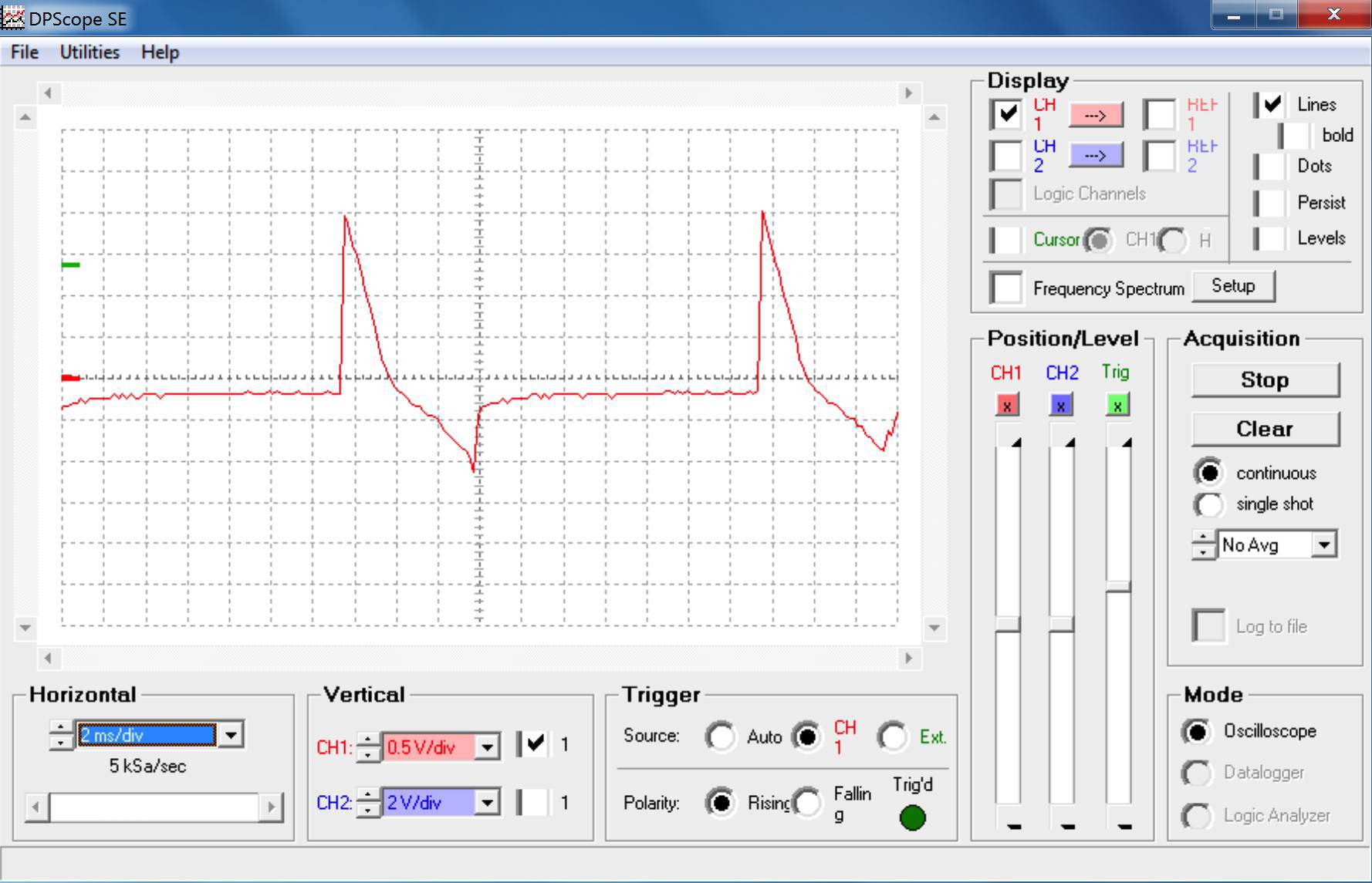
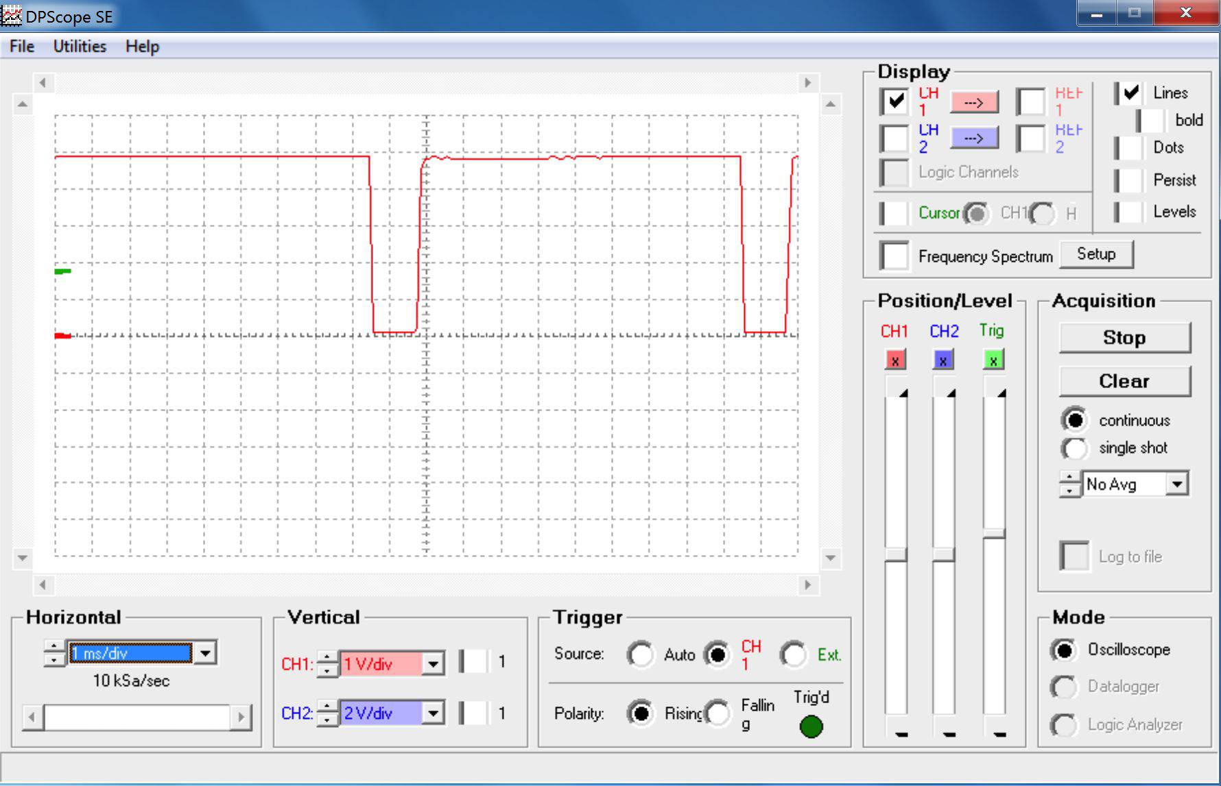
I've managed to add most of the features I wanted to add to aArtisanQ. Here's a list of changes since my last update. 1) Added RoR calcs. 2) Echoing of serial commands on the LCD is now optional. 3) Temp units can now be changed during PID control. 4) ANLG1 is no longer read during PID control. 5) Added support for LCDapter buttons and LEDs. Button 1 currently activates or deactivates PID control. 6) ANLG2 input range can be customised. 7) Added optional safety feature that cuts power to OT1 if OT2 is below a certain value (useful for air roasters). Required modification to phase_ctrl.cpp. 8) Tidied up LCD display. The updated code is attached if anyone want's to have a play. Note that it needs the PID library in addition to the standard TC4 libraries Jim, I've also attached some waveforms I'm getting with my own ZCD board (showing ZCD input in red and OT2 output in blue). Do these look right?
greencardigan attached the following files:
greencardigan attached the following images:


|
|
|
|
| greencardigan |
Posted on 09/22/2012 4:16 AM
|
|
1 1/2 Pounder Posts: 1185 Joined: November 21, 2010 |
Also the TC4 channel used for the PID process variable and the channel used for the displayed RoR can be set in user.h. |
|
|
|
| JimG |
Posted on 09/22/2012 11:00 AM
|
|
1 1/2 Pounder Posts: 834 Joined: October 23, 2008 |
Brad - This is a great piece of work, and a significant contribution to the TC4 project. Thanks on behalf of everyone who will enjoy using it! I have created a new trunk area in the project googlecode site for aArtisan_PID, as well as a tag folder containing the code for release 8_2. http://code.googl...rtisan_PID. I have also posted a new download that contains both aArtisanQ_PID and Profile_Loader. There were no code changes made, so users can either download using the links in your post, or can go to the project repository: http://code.googl...loads/list Offline, you and I should discuss how best to maintain and develop your code branch. If you wish to use SVN and the project site, it is configured now to allow this. If you prefer to develop locally and post releases, then I will handle getting revisions on to the project site. Either way works for me! Jim |
|
|
|
| JimG |
Posted on 09/22/2012 11:10 AM
|
|
1 1/2 Pounder Posts: 834 Joined: October 23, 2008 |
Quote greencardigan wrote:Jim, I've also attached some waveforms I'm getting with my own ZCD board (showing ZCD input in red and OT2 output in blue). Do these look right? Yes, they do look correct, assuming that image 1 represents a low output level (i.e. with a long phase delay) and that image 2 represents a high output level (i.e. a very short, or zero, phase delay). The red line is doing what I would expect, that is, it is going low at a frequency of approximately 100Hz (2 x your line frequency). The blue line is lagging behind the falling red signal and is high only for the short firing pulse to the TRIAC. You can adjust the width of the TRIAC firing pulse if you wish, but there's no real harm in having it longer than needed. It just has to be long enough to latch the TRIAC until the next zero cross. You can also adjust the lag between the fall of the red signal and the "zero" point of the start of phase angle timing. If you notice that the TRIAC is behaving oddly, then you can adjust this lag. With an inductive load, the current (which is what the TRIAC responds to) and voltage (which is what the ZCD responds to) can get a little out of phase and the lag variable can help. Jim |
|
|
|
| greencardigan |
Posted on 09/22/2012 6:19 PM
|
|
1 1/2 Pounder Posts: 1185 Joined: November 21, 2010 |
Quote JimG wrote: Yes, they do look correct, assuming that image 1 represents a low output level (i.e. with a long phase delay) and that image 2 represents a high output level (i.e. a very short, or zero, phase delay. Yes the first image was at 5% and the second was at 100%. |
|
|
|
| JimG |
Posted on 09/23/2012 10:13 AM
|
|
1 1/2 Pounder Posts: 834 Joined: October 23, 2008 |
Quote JimG wrote: I have created a new trunk area in the project googlecode site for aArtisan_PID, as well as a tag folder containing the code for release 8_2. http://code.googl...rtisan_PID. I have also posted a new download that contains both aArtisanQ_PID and Profile_Loader. There were no code changes made, so users can either download using the links in your post, or can go to the project repository: http://code.googl...loads/list I made a mistake with the versioning, which has since been corrected. The correct version for Brad's aArtisanQ_PID release is 2.8: http://code.googl...rtisan_PID The downloadable zip file is here: http://code.googl...loads/list Jim |
|
|
|
| smico |
Posted on 10/15/2012 6:25 PM
|
 1/2 Pounder  Posts: 262 Joined: December 17, 2011 |
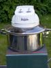
How to plug TC4 to Arduino Mega 2560 Two pins are different: SDA and SCL and they need to be connected to respective pins on Mega: Communication 20 and 21. I bended pins on TC4 so both Male to Male, or Female to Male wires can be used.
smico attached the following image:

Hottop B2 + HTC, Cremina 83, OE Pharos, Brewtus IIIR, Baratza Vario
|
|
|
|
| greencardigan |
Posted on 11/08/2012 6:04 AM
|
|
1 1/2 Pounder Posts: 1185 Joined: November 21, 2010 |
Hi Jim I've having some issues with my Arduino running aArtisanQ_PID. It looks like it could be a similar problem that Bhante was having. I'm not sure if he got his problem sorted? My Arduino stops responding after a while with the serial communication, potentiometers and LCD screen all becoming inactive. However the fan and heater continue to run at the last set power levels. How can that be?? I thought the phase control and ICC code would stop running. I've been doing some testing to try and isolate the cause of the problem. The freezes have occured with the following conditions. - Arduino powered by the USB port on my Win7 laptop and my MacBook pro. - heater off but fan on - no logging software running The only configuration that I haven't been able to get it to freeze is when power is supplied to the Arduino using a USB cable connected to a 5V phone charger instead of a laptop. Also I don't believe I had any freezes when I was testing my code without the heater and fan connected. Any suggestions? |
|
|
|
| JimG |
Posted on 11/08/2012 1:44 PM
|
|
1 1/2 Pounder Posts: 834 Joined: October 23, 2008 |
Hi, Brad - My best guess is that EMI is being generated by the fan motor. The fan is an inductive load and a voltage spike is produced in an inductor when the current changes. The fact that the behavior is different with a different power source (phone charger vs USB port on a computer), and when the fan is not on, are both consistent with that theory. I, and others, have observed similar behavior with microprocessor boards used to control espresso machines. When the water pump and/or solenoid valve are turned off, about 1 in 100 times the microprocessor will freeze up from the pulse that is generated by the collapsing magnetic field. Bill Crossland just sent me an EMI filter to try that has worked for him on some of his projects. I haven't had a chance to test it yet, but will let you know what I find out. In the meantime, I you might try connecting a RC snubber across the fan leads (basically I think Bill's filter is a snubber). Jim |
|
|
|
| greencardigan |
Posted on 11/08/2012 3:53 PM
|
|
1 1/2 Pounder Posts: 1185 Joined: November 21, 2010 |
Ok thanks Jim. Any thoughts on why the fan and heater still keep running even though the microprocessor appears to have frozen up? I'll have a bit of a read up on EMI and snubbers. What about putting the arduino/TC4 in a metal enclosure? |
|
|
|
| JackH |
Posted on 11/08/2012 4:18 PM
|
 Administrator Posts: 1809 Joined: May 10, 2011 |
Jim, Is this a problem where the TC-4 is too close to the fan or is the fan's noise getting on the power supply lines? --Jack ---Jack
KKTO Roaster. |
|
|
|
| JimG |
Posted on 11/08/2012 10:22 PM
|
|
1 1/2 Pounder Posts: 834 Joined: October 23, 2008 |
Quote greencardigan wrote: Any thoughts on why the fan and heater still keep running even though the microprocessor appears to have frozen up? I think because the outputs are interrupt driven. At every AC zero cross an interrupt is triggered, which I guess doesn't rely on the instruction pointer to execute its code? Jim EDIT: This might be a good application for a watchdog timer, I think. Set it up to shut things down if the main program code doesn't kick it every so often. Edited by JimG on 11/08/2012 10:27 PM |
|
|
|
| JimG |
Posted on 11/08/2012 10:23 PM
|
|
1 1/2 Pounder Posts: 834 Joined: October 23, 2008 |
Quote JackH wrote: Is this a problem where the TC-4 is too close to the fan or is the fan's noise getting on the power supply lines? Power supply lines is my best guess. Jim |
|
|
|
| greencardigan |
Posted on 11/10/2012 11:53 PM
|
|
1 1/2 Pounder Posts: 1185 Joined: November 21, 2010 |
OK let us know how the EMI filter goes. I found these docs which I thought were interesting and relevant. http://www.ti.com...lup100.pdf http://www.vishay...accaps.pdf Would I be ok having the Arduino powered from the DC jack as well as having a USB cable connected to a laptop? |
|
|
|
| Dan |
Posted on 11/11/2012 9:08 AM
|
|
1 1/2 Pounder Posts: 1662 Joined: October 24, 2005 |
Would a choke on the power supply line(s) be useful in this application? |
|
|
|
| JimG |
Posted on 11/12/2012 8:47 AM
|
|
1 1/2 Pounder Posts: 834 Joined: October 23, 2008 |
Quote Dan - This is a very interesting question. I've noticed that the commercial PID controllers I've autopsied all have common mode chokes on board between line power input and their AC-DC converters -- and that they do not suffer from this problem. I have a few common mode chokes here, but haven't gotten around to doing any testing. It doesn't help that the problem occurs so infrequently that testing is very difficult. Jim |
|
|
|
| JimG |
Posted on 11/12/2012 8:51 AM
|
|
1 1/2 Pounder Posts: 834 Joined: October 23, 2008 |
Quote greencardigan wrote: Would I be ok having the Arduino powered from the DC jack as well as having a USB cable connected to a laptop? Yes, this is OK. The Arduino's and the TC4C have circuitry that automatically switches the V+ input from USB to the DC jack when a DC voltage above around 7V is detected on the jack. But .... ground (V-) will remain connected to both the USB and DC jack in this configuration. It is only the V+ that is switched over to external. Jim |
|
|
|
| greencardigan |
Posted on 11/13/2012 7:12 AM
|
|
1 1/2 Pounder Posts: 1185 Joined: November 21, 2010 |
I think I have fixed my freezing/reseting problem. I did the following. - Powered the arduino from a 7.5V DC power supply rather than USB - Putting ferrite beads on most of the inputs to the Arduino/TC4 - Adding an X2 suppression capacitor across the 240V AC fan supply. But I have now been having another strange problem! I noticed that if I touched the metal braid on my thermocouples or my macbook case if the usb cable was connected then the power to the fan got mucked up with the waveform becoming weird. I checked the waveform on my scope but didn't get a screen shot. It was only happening with the fan power at 65% or lower. And this only happens when my bare feet were touching the concrete floor! The controller is wired the same as Jim's example except I have two separate power circuits. One for the fan and TC4 and the other for the heater. http://www.mlgp-l...111120.jpg I completely disconnected the heater power and disconnected the heater and touching the neutral power wire on the heater circuit causes the same issue. The neutral line goes through the zero cross SSR. I then disconnected the 5V power I had going to the zero cross detector (I think Jim said this 5V connection wasn't necessary) and the problem became worse. I could now just move my hand near the control box (without touching it) and the fan power would by mucked up. Any ideas? I'm a bit baffled by this one. Maybe I could try replacing the zero cross SSR? |
|
|
|
| JimG |
Posted on 11/13/2012 9:53 AM
|
|
1 1/2 Pounder Posts: 834 Joined: October 23, 2008 |
Brad - Good to know that you solved the freeze-up problem. Perhaps the X2 capacitor is acting as a snubber? Regarding the weird waveform, my guess is that the problem lies with noise in the signal coming from the ZCD board to the TC4. Can you put a scope on the ZCD output signal? Measure the voltage between the ZCD output pin and GND. It should be constant 5V except when the AC crosses zero every 10ms. At the zero crosses the signal should drop to 0V for 1ms or thereabouts. The software on the ATmega watches for a falling voltage and interprets this as the zero cross. If there is noise then the processor will be tricked into thinking a zero cross has occurred when in fact it has not. This would cause the timing to get really messed up for the fan control signals. Jim |
|
|
|
| greencardigan |
Posted on 11/14/2012 4:43 AM
|
|
1 1/2 Pounder Posts: 1185 Joined: November 21, 2010 |
I've checked the pulses coming from the ZCD and it looks ok even when the fan output is weird. I have attached some of the waveforms I recorded. I can create the problem when I probe the positive pin on OT1 and OT2. And also by just touching the insulation on the leads going from the TC4 to the SSRs. And in some circumstances it occurs by just putting my hand near the leads. I mentioned in my previous post that the problem only occurs when the fan power is set to 65% or less. And I also noticed that having the heater set at 100% stops the problem and at 0% it is at its worst. Also attached are waveforms for the fan output at 50% with and without the weird waveform. I was probing the output of a 15VAC wall-wart connected in parallel with the fan. I'm thinking of trying the following when I get a chance. - connecting mains earth to the TC4 ground. Any reason I shouldn't do this? - load an old version of the arduino code to see if that helps? - replacing my SSR - ???
greencardigan attached the following images:

|
|
|
|
| JimG |
Posted on 11/14/2012 8:07 AM
|
|
1 1/2 Pounder Posts: 834 Joined: October 23, 2008 |
What I can offer is that something is messing with the timing of the TRIAC (i.e. SSR) firing. I'm not sure what it is, though. Here's what I see: 1. In the "good" trace, there is still voltage present after the zero cross. This is probably because the fan load has enough inductance so that the line voltage and fan current are out of phase. TRIAC's switch off when the current is zero, but the ZCD detects when the voltage crosses zero. The Arduino is sending "on" signals to the gate based on voltage, and relies on the TRIAC to turn itself off at the end of each half-wave. 2. In the "bad" trace, the firing of the TRIAC is delayed, and then there is a very odd-looking voltage still present after the zero cross. I'm not sure what is causing the delay in switching on the TRIAC. But I suspect the weird trace after the zero cross might be coming from voltage stored in the wall wart? 3. Unfortunately, there's no way to be sure that the AC wave coming from the wall wart is in phase with the line AC, is there? I suppose it is possible that your measurements have a phase delay in them as the result of the wall wart (I am speculating here). There are two timing parameters you can play with in the code (note that the values are in "counts", not in uS). First, there is ZC_LEAD, the presumed delay between when the ZCD signal goes low and the "real" zero cross of the AC current. The default value would be around 500uS for a purely resistive load. This is based on the observation that the pulse width coming from the ZCD is around 1000uS in width and is centered about the true voltage zero cross. You can try larger values of this zero offset parameter to try and compensate for the fact that the current and voltage may be out of phase. Second, you can adjust the width of the TRIAC firing pulse (TRIAC_PULSE_WIDTH). The pulse to the gate of the TRIAC only needs to be long enough to latch the TRIAC. If this pulse is too short then the TRIAC may not get fired. For my popper motor I found (by trial and error) that this width needed to be no less than 2mS. If this pulse is too long then it may overlap into the next half wave (although I think the code automatically turns off the gate signal at each zero cross regardless of whether the TRIAC pulse is done). You might try different approaches to this. One approach would be to simply leave the gate signal high until the next zero cross. This wastes a little power, but otherwise shouldn't be a problem. The other approach might be to shorten the pulse width to the minimum required to latch the TRIAC. In a perfect world, you would set up your scope to simultaneously measure the current to the fan and the signal coming from the ZCD to see if there is a phase shift. You might also track the ZCD signal against the gate signal to the TRIAC, both with the fan connected and with it disconnected. Try and determine which of these 3 possibilities is the culprit: 1) phase shift of AC line voltage versus fan current 2) incorrect timing/width of the TRIAC firing pulse 3) noise on the gate signal to the TRIAC Another thought: Keep in mind that OT1 and OT2 are both open collector outputs. So OT2(+) will be at +5V and and OT2(-) will be floating until the processor puts a voltage on the base of the transistor to pull OT2(-) to GND. Anything that allows OT2(-) to go to GND will fire the TRIAC. Maybe an open collector is not the ideal arrangement here and going directly to the MCU pin for OT2 would work better? You might also try a 10K resistor across the OT2 pins to keep OT2(-) pulled up when OT2 should be off? Finally, you might try putting the heater on OT2 and the fan on OT1. Phase angle control should work flawlessly on the heater since it is a resistive load. And the ICC control on OT1 worked pretty well on my popper motor. In my test setup, all I had to do was connect the output from SSR1 to the fan and from SSR2 to the heater to give it a try. Jim |
|
|
|

| Jump to Forum: |
Powered by PHP-Fusion Copyright © 2024 PHP-Fusion Inc
Released as free software without warranties under GNU Affero GPL v3
Designed with ♥ by NetriXHosted by skpacman