
Login

Shoutbox
You must login to post a message.
renatoa
07/26/2024 3:49 PM
Bill grubbe and Jk, 
allenb
07/26/2024 5:15 AM
Spiderkw Welcome to HRO!

renatoa
07/24/2024 8:31 AM
ramiroflores and John123,

 ?
?
?renatoa
07/21/2024 1:18 AM
 , Luislobo
renatoa
07/19/2024 11:28 AM
Koepea,
Forum Threads
Newest Threads
Skywalker roaster modsBackground Roast Iss...
Hello from Arkansas
TC4ESP
Green coffee reviews
Hottest Threads
| Skywalker roaster... | [375] |
| TC4ESP | [115] |
| War on Farmers by... | [47] |
| Adventures in flu... | [26] |
| Hello! (soon) Roa... | [17] |
In Memory Of Ginny

Donations
Latest Donations
dmccallum - 10.00
JackH - 25.00
snwcmpr - 10.00
Anonymous - 2.00
Anonymous - 5.00
dmccallum - 10.00
JackH - 25.00
snwcmpr - 10.00
Anonymous - 2.00
Anonymous - 5.00
Users Online
Guests Online: 6
Members Online: 0
Total Members: 8,393
Newest Member: Bill grubbe
Members Online: 0
Total Members: 8,393
Newest Member: Bill grubbe
View Thread
Who is here? 1 guest(s)
 TC4 - Coding and tech issues
|
|
| greencardigan |
Posted on 11/14/2012 4:34 PM
|
 1 1/2 Pounder  Posts: 1185 Joined: November 21, 2010 |
Thanks Jim, that's given me a few things to try. I also like the idea of driving the SSR directly from an Arduino output pin but will try the pullup resistor on OT1(-) and OT2(-) first. Yes. I'll definitely try to scope the ZCD pulse and the base of the OT1 transistor at the same time to see if the timing is changing. Yes, I wondered if probing the wall-wart output was showing my true waveform for the fan. |
|
|
|
| greencardigan |
Posted on 11/15/2012 3:26 AM
|
|
1 1/2 Pounder Posts: 1185 Joined: November 21, 2010 |
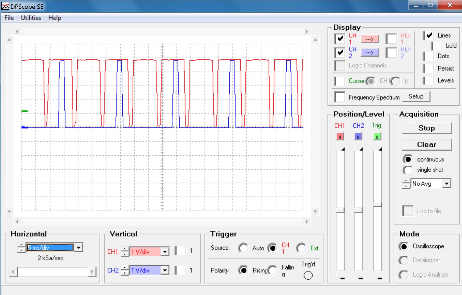
Jim Here's some more waveforms showing the ZCD pulse combined with the output on the Arduino's digital outputs for OT1 and OT2. The ZCD pulse looks stable in all cases. When the fan is going weird it seems that OT2 is only triggering every second half cycle. And the majority (7 of 8?) of OT1 pulses seem to reduce in width to about 5ms instead of 10ms. AND this all still happens with both the fan and heater disconnected! I haven't yet tried any of the your other suggestion. Should I start a new thread instead of clogging this one up?
greencardigan attached the following images:

|
|
|
|
| greencardigan |
Posted on 11/15/2012 3:32 AM
|
|
1 1/2 Pounder Posts: 1185 Joined: November 21, 2010 |
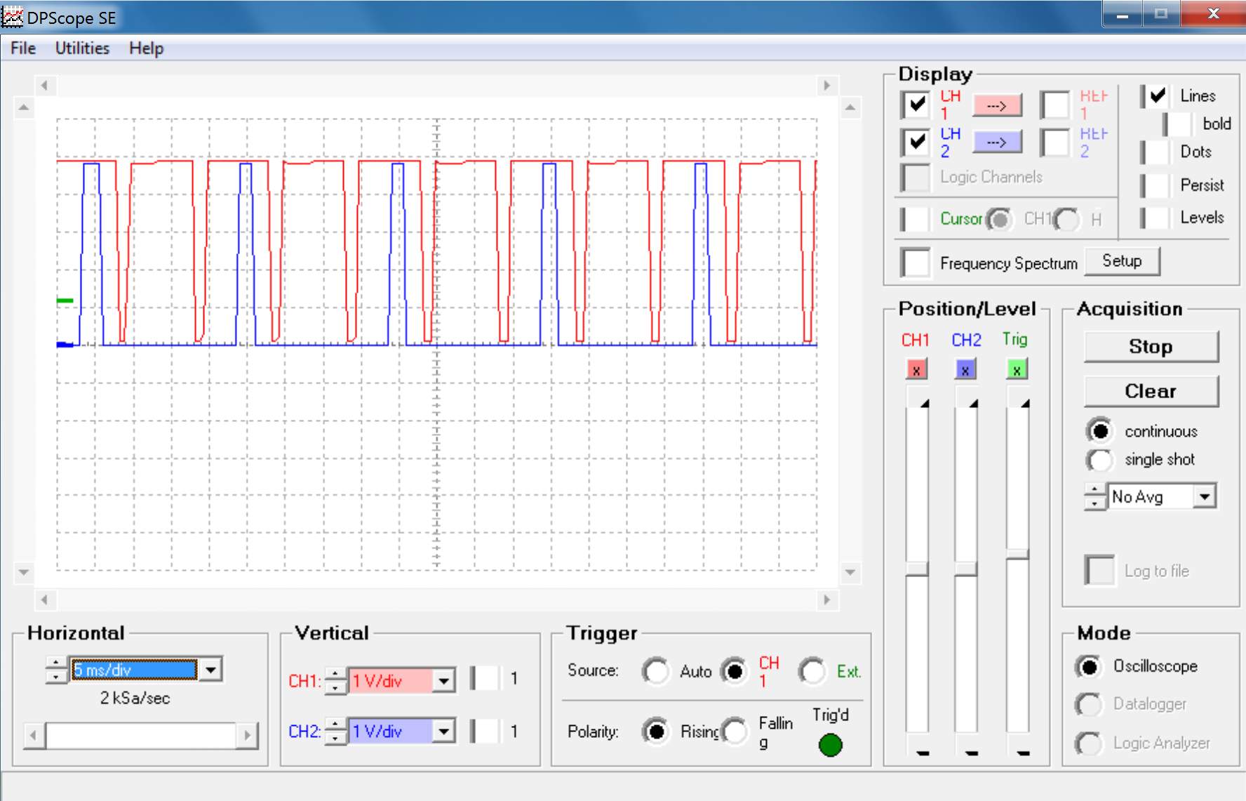
And here's the waveforms showing the ZCD pulse and OT2.
greencardigan attached the following images:


|
|
|
|
| greencardigan |
Posted on 11/15/2012 3:36 AM
|
|
1 1/2 Pounder Posts: 1185 Joined: November 21, 2010 |
And some good news is that I have a cheap ebay bluetooth module working well for wireless logging and roaster control.  |
|
|
|
| greencardigan |
Posted on 11/15/2012 3:48 AM
|
|
1 1/2 Pounder Posts: 1185 Joined: November 21, 2010 |
Quote Sorry that should read OT1 not OT2. Sometimes the edit post option is not available?? |
|
|
|
| JimG |
Posted on 11/15/2012 11:10 AM
|
|
1 1/2 Pounder Posts: 834 Joined: October 23, 2008 |
That information is very helpful to understand what is happening. Now to try and figure out why! What sketch was running when you made these graphs? I would like to try and reproduce the problem here. Jim |
|
|
|
| greencardigan |
Posted on 11/15/2012 4:34 PM
|
|
1 1/2 Pounder Posts: 1185 Joined: November 21, 2010 |
Yes that's right. But working out why is the hard part. I've attached the code I currently have loaded. It's a slight variation of what's in the aArtisan_PID trunk directory in the repository.
greencardigan attached the following file:
|
|
|
|
| greencardigan |
Posted on 11/16/2012 8:18 AM
|
|
1 1/2 Pounder Posts: 1185 Joined: November 21, 2010 |
I tried the 10K resistors across OT1 and OT2 and also connecting mains earth to the TC4 but this didn't help. In fact it was worse with the ground connected. I then noticed that lifting the cables from OT1 and OT2 up out of the project box made the problem go away. So I hot glued some of the the cables into position and it's working fine at the moment! But I'm still don't really have any idea what was happening. I'll keep you posted if it plays up again. I still haven't had any more freezes or resets yet either. |
|
|
|
| Dan |
Posted on 01/24/2013 12:35 PM
|
|
1 1/2 Pounder Posts: 1662 Joined: October 24, 2005 |
I got some chokes by accident in a shipment of magnets last year. They are 30mm x 5mm. Pictured is one wrapped with #14 wire, and two rolls with about fifty in each roll. I have about 20 rolls. I'd be happy to mail some these to any experimenters. Just PM me with your mailing address. If they deal with the RF issue, the developers might want a couple of rolls to ship with every TC4 board.
Dan attached the following image:

1 pound electric sample roaster, 3 pound direct-flame roaster, both handmade; modified Mazzer Mini grinder, LaSpaziale Vivaldi II automatic espresso machine. When the electricity goes out I make vacpot coffee from beans ground on my Zassenhaus hand grinder, and heat the water with a teakettle on the gas range.
|
|
|
|
| Dan |
Posted on 01/24/2013 4:21 PM
|
|
1 1/2 Pounder Posts: 1662 Joined: October 24, 2005 |
I have no idea how many turns you need on the coil to create the inductance you want. Here are some resources. http://www.physic...p?t=616605 http://en.wikiped...i/Inductor 1 pound electric sample roaster, 3 pound direct-flame roaster, both handmade; modified Mazzer Mini grinder, LaSpaziale Vivaldi II automatic espresso machine. When the electricity goes out I make vacpot coffee from beans ground on my Zassenhaus hand grinder, and heat the water with a teakettle on the gas range.
|
|
|
|
| Bhante |
Posted on 03/16/2013 3:42 PM
|
 1/2 Pounder  Posts: 228 Joined: February 13, 2011 |
Quote greencardigan wrote: I think I have fixed my freezing/reseting problem. I did the following. - Powered the arduino from a 7.5V DC power supply rather than USB - Putting ferrite beads on most of the inputs to the Arduino/TC4 - Adding an X2 suppression capacitor across the 240V AC fan supply. When I had my TC4 on my Espresso machine a year ago or so I also found differences involving the power supply - with one USB power adaptor it would crash all the time, while with another only occasionally. I think the difference was that the voltage and/or current from the first was not adequate. Since my move last year I've been having vastly more of the crashes, and I've traced the source of most of the to the fridge and/or freezer. Now I have to unplug the fridge and freezer before roasting, and hope I remember to switch it back on again! Some other things also cause crashes, such as the energy saving lamp I was until recently using for seing inside the hottop. Now I have fixed up a little LED lamp which illuminates the coffee much better anyway (I was hoping to use 12V from the hottop mainboard, but it seems the 12V supply is already not fully sufficient for the fan, and so the fan setting heavily affects the lamp). Now I am planning to try some of Dan's chokes on the signal lines (thanks Dan!), and will report back whether I get any success or not. Bhante |
|
|
|
| greencardigan |
Posted on 03/20/2013 4:32 AM
|
|
1 1/2 Pounder Posts: 1185 Joined: November 21, 2010 |
I'm having a little issue with my thermocouple readings. When i touch the roast chamber or braided thermocouple shielding, I sometimes get a sudden negative drop in the temp reading. See the graph below just after the 8 minute mark. Does this suggest I need to ground the thermocouple inputs? Maybe using the spaces left for resistors on the TC4 board?  |
|
|
|
| Bhante |
Posted on 03/20/2013 5:03 AM
|
|
1/2 Pounder Posts: 228 Joined: February 13, 2011 |
Quote greencardigan wrote: When i touch the roast chamber or braided thermocouple shielding, I sometimes get a sudden negative drop in the temp reading. I've had blips exactly like that from time to time, I think from slightly moving thermocouple cable or USB cable, or conceivably from touching the cable or roaster; touching the metal parts of the roaster is unlikely though because it is hot, and the cable is not with a metal sheath. I had always assumed it was a contact issue, but it could also be capacitative on the thermocouple. What kind of thermcouples are you using? |
|
|
|
| greencardigan |
Posted on 03/20/2013 5:41 AM
|
|
1 1/2 Pounder Posts: 1185 Joined: November 21, 2010 |
I'm using cheap probes from eBay like these. http://www.ebay.c...1244420165 |
|
|
|
| JimG |
Posted on 03/20/2013 6:06 AM
|
|
1 1/2 Pounder Posts: 834 Joined: October 23, 2008 |
Quote greencardigan wrote:Does this suggest I need to ground the thermocouple inputs? Maybe using the spaces left for resistors on the TC4 board? This could be a ground loop effect caused by the difference in potential between the TC4's GND plane and the roaster shell. If so, then one option is to force the GND plane and the roaster shell to be the same by connecting them with a wire (optionally through a 1K to 10K resistor). Use the 2-pin GNDPT header on the TC4 for this. Lately I have been experimenting with a different solution, however, that is showing some promise. Instead of using resistors on those empty pads I have been using 0.1uF ceramic capacitors. In the limited testing I've done this has eliminated the ground loop temperature offset without having to tie the roaster and GND planes together. The other possibility is that touching the probe leads is causing an internal short between the shielding on the probe and the thermocouple wires? This might cause a similar result. Jim |
|
|
|
| greencardigan |
Posted on 03/20/2013 6:39 AM
|
|
1 1/2 Pounder Posts: 1185 Joined: November 21, 2010 |
Thanks for the tips. I'll try grounding the roaster shell and thermocouple shielding first to see if that helps. |
|
|
|
| Bhante |
Posted on 03/27/2013 5:32 PM
|
|
1/2 Pounder Posts: 228 Joined: February 13, 2011 |
@ Jim: In case you plan to make any new versions of the TC4 shield, here are a few suggestions: 1) It would be useful to be able to separate the I2C lines from A4 and A5, as there are many new versions of the Arduino these days, many of which use different pins for I2C, and it would seem a pity to lock users in to old technology. I suggest a simple solder jumper connection on the circuit board, which uses very little extra space. As long as the chips on board remain connected to the I2C header on the shield, the SDA and SCL lines can then be disconnected from A4 and A5 and connected by jumper leads to wherever the appropriate I2C pins are. If real estate permits, you could put an extra 2-pin header hole for SDA and SCL adjacent to the I2C header to facilitate connecting the jumpers, or if space does not permit the wires will just have to be forked. 2) Some boards use 3.3V instead of 5V. It would be worth giving a little thought to the implications of this, however it may not be serious - the Olimexino for example has both the Arduino 3.3V and "5V" pins powered with 3.3V, so with existing wiring the I2C header on the shield remain powered by 3.3V as required. Vin on the Olimexino can be anything up to 30V (the 24V battery on a heavy goods vehicle, for example), so in the case of the Olimexino we certainly don't want I2C connected to the Vin pin. As for other boards I don't know. With 3.3V boards the I2C chips on the shield can remain at 3.3V, while a little step-up board can be put in between the I2C header and the LCD to give the 5V the LCD probably requires. 3) What about putting holes on the shield for an optional jumper to short the thermocouple contacts together, where particular channels are not used? Here it makes more sense to use a pin header type jumper rather than a solder jumper, so that it can readily be inserted or removed as required, instead of having to use a special external plug. What I have found implies that for example leaving channels 3 and 4 unconnected while using channels 1 and 2 will introduce errors on channels 1 and 2, even if only 2 channels are selected in the software (and likewise for channel 2 if using only channel 1). However I have only briefly tested the effect of setting the number of channels in the software so it is possible I could be wrong on this. 4) You may remember I once suggested putting a couple of small holes (circa 0.5mm) on the edge of the board where the thermocouple wires come out from the screw connectors so that the thermocouple wires can be secured in place with a piece of nylon filament (fishing line etc). If the Arduino is mounted in a box with the USB socket accessible to the outside, and thermocouple sockets are also mounted in the box, then the wires from the TC4 to the thermocouple sockets necessarily have to bend very very sharply indeed coming out of the screw sockets. This puts an awful lot of strain on them especially when using braided thermocouple wire, and I find they come loose very easily. I find these tiny little screw clamps have great difficulty clamping the wires firmly, although it will probably depend on the type of wire and the number of filaments in the wire, size of wire etc. So I think it would be very helpful to be able to bind them in place with a little nylon filament. 5) I would much prefer to have the thermocouples moved to any one of the other 3 sides of the board, but the conclusion last time we discussed this was that there is simply not the space available to achieve this; nevertheless I'll leave this suggestion here in case you think it makes sense to turn the bourd around. Putting the OT1, OT2, I/O3 connectors on the USB side obviously makes some sense for easy connections to the roaster and the thermocouples can then be on the opposite side, but that is only possible by changing the whole layout which you probably don't want to do. 6) Just a wild idea - have you ever thought about a move away from the shield concept altogether? After all, since we are no longer using the parallel LCD pins, most of the Arduino connections are now through the I2C port, apart from the PWM pins and optionally the analog pins. Therefore instead of mounting the board on the Arduino as a shield you have it adjacent with a handful of pins coming out for I2C, PWM and analog, which can then be connected to whatever pins you like on the microprocessor. I am thinking of this from three perspectives: firstly this leaves more or even all the arduino shield pins free for any other shields you might want to connect (on some of the Arduino compatibles for example you can connect all the I2C, PWM and Analog pins you need to non-shield pins); secondly some Arduino boards and likewise some compatibles have certain incompatible pins such as I2C etc, and also boards like the Nano have their pins in completely different places; and thirdly the TC4 can potentially be used in many different ways with many different microprocessors, most of which do not have the Arduino form factor. There is no reason not to connect it to an STM32 Discovery board for example, if someone wants to modify the software and libraries or use completely different software. As you might gather from the above I am looking closely at the Olimexino (Maple compatible) at the moment, which has many attractive features such as a STM32F103RB ARM Cortex M3 32 bit processor running at 72MHz, 128kB flash, 20kB RAM, noise immune design (according to the manufacturer), industrial operating temperature range, 3.3V to 30VDC input, automobile/industrial environment compatible, built-in LiIon charger and automatic power switching between USB, DC and LiIon (unlike the Maple where you have to set jumpers), ultra low power design, 37 digital IO pins, 16 PWM pins all at 16 bit, 15 Analog pins at 12 bit, 2 I2C ports, 2 SPI ports, 3 serial ports plus independent USB port, 4 timers all much more advanced and flexible than the Arduino timers, built-in real time clock, built-in microSD socket, CAN port, etc etc ... all at less than the price of an Arduino (at official prices) and only half the cost of the far inferior Maple. The board manufacture quality looks excellent. With the Olimexino or something similar you could probably put all the Processing software onto the board itself, mount a 5 inch TFT/touchscreen for realtime onboard plotting, and log results to the microSD card and store profiles there. Probably you could also use a (replacement) iPhone display and touchscreen, which you can buy as spare part from China for about 10 to 15 Euros (or other smartphone displays - some of them probably have easier interfaces than others). That seems to me to be the way for the future. Bhante (Sorry it's a long post, hope your coffee is not cold!) |
|
|
|
| bvwelch |
Posted on 03/27/2013 8:14 PM
|
 1 1/2 Pounder Posts: 1064 Joined: December 27, 2007 |
I did some early prototyping for the TC4, at 3.3 volts with a JeeNode. So the essential chips will run fine at 3.3 volts. I have a 3.3 volt LCD but no time to play with it. Another project waiting in the wings is the marrying the TC4 to the Raspberry Pi. -- so many projects, so little time. |
|
|
|
| Bhante |
Posted on 03/28/2013 5:46 PM
|
|
1/2 Pounder Posts: 228 Joined: February 13, 2011 |
... Jump ahead to 2020 ... wait, maybe 2015 ... Hmm, would be nice to have one of these onboard the TC4: the chip: http://www.ti.com...uct/cc2541 application example: http://www.ti.com...1dk-sensor http://processors..._SensorTag http://processors...User_Guide Bhante |
|
|
|
| JimG |
Posted on 04/01/2013 6:54 AM
|
|
1 1/2 Pounder Posts: 834 Joined: October 23, 2008 |
Quote Bhante wrote: 1) It would be useful to be able to separate the I2C lines from A4 and A5, as there are many new versions of the Arduino these days, many of which use different pins for I2C, and it would seem a pity to lock users in to old technology. I suggest a simple solder jumper connection on the circuit board, which uses very little extra space. As long as the chips on board remain connected to the I2C header on the shield, the SDA and SCL lines can then be disconnected from A4 and A5 and connected by jumper leads to wherever the appropriate I2C pins are. If real estate permits, you could put an extra 2-pin header hole for SDA and SCL adjacent to the I2C header to facilitate connecting the jumpers, or if space does not permit the wires will just have to be forked. This is actually already in the works. Quote Bhante wrote: 2) Some boards use 3.3V instead of 5V. It would be worth giving a little thought to the implications of this, however it may not be serious - the Olimexino for example has both the Arduino 3.3V and "5V" pins powered with 3.3V, so with existing wiring the I2C header on the shield remain powered by 3.3V as required. Vin on the Olimexino can be anything up to 30V (the 24V battery on a heavy goods vehicle, for example), so in the case of the Olimexino we certainly don't want I2C connected to the Vin pin. As for other boards I don't know. With 3.3V boards the I2C chips on the shield can remain at 3.3V, while a little step-up board can be put in between the I2C header and the LCD to give the 5V the LCD probably requires. The output stages of the TC4 currently use BJT's in an open collector arrangement. I doubt this will work well at 3.3V. Future versions of the TC4 will probably use NMOS instead. LCD panels which operate at 3.3V are available. VIN is not used for anything on the TC4 these days. Quote Bhante wrote: 3) What about putting holes on the shield for an optional jumper to short the thermocouple contacts together, where particular channels are not used? Here it makes more sense to use a pin header type jumper rather than a solder jumper, so that it can readily be inserted or removed as required, instead of having to use a special external plug. What I have found implies that for example leaving channels 3 and 4 unconnected while using channels 1 and 2 will introduce errors on channels 1 and 2, even if only 2 channels are selected in the software (and likewise for channel 2 if using only channel 1). However I have only briefly tested the effect of setting the number of channels in the software so it is possible I could be wrong on this. Good idea. Real estate is difficult in that area, but I will try and implement. Probably will require a larger shield footprint, though. Quote Bhante wrote: 4) You may remember I once suggested putting a couple of small holes (circa 0.5mm) on the edge of the board where the thermocouple wires come out from the screw connectors so that the thermocouple wires can be secured in place with a piece of nylon filament (fishing line etc). If the Arduino is mounted in a box with the USB socket accessible to the outside, and thermocouple sockets are also mounted in the box, then the wires from the TC4 to the thermocouple sockets necessarily have to bend very very sharply indeed coming out of the screw sockets. This puts an awful lot of strain on them especially when using braided thermocouple wire, and I find they come loose very easily. I find these tiny little screw clamps have great difficulty clamping the wires firmly, although it will probably depend on the type of wire and the number of filaments in the wire, size of wire etc. So I think it would be very helpful to be able to bind them in place with a little nylon filament. Again, this is simply a matter of real estate. I liked the idea then, and still like it. But the shield would have to become bigger to accommodate. Quote Bhante wrote: 5) I would much prefer to have the thermocouples moved to any one of the other 3 sides of the board, but the conclusion last time we discussed this was that there is simply not the space available to achieve this; nevertheless I'll leave this suggestion here in case you think it makes sense to turn the bourd around. Putting the OT1, OT2, I/O3 connectors on the USB side obviously makes some sense for easy connections to the roaster and the thermocouples can then be on the opposite side, but that is only possible by changing the whole layout which you probably don't want to do. I'll have a look at this in association with developing the changes needed for the new locations of the I2C pins. It is a pretty major rearrangement of the board! Quote Bhante wrote: 6) Just a wild idea - have you ever thought about a move away from the shield concept altogether? After all, since we are no longer using the parallel LCD pins, most of the Arduino connections are now through the I2C port, apart from the PWM pins and optionally the analog pins. Therefore instead of mounting the board on the Arduino as a shield you have it adjacent with a handful of pins coming out for I2C, PWM and analog, which can then be connected to whatever pins you like on the microprocessor. I am thinking of this from three perspectives: firstly this leaves more or even all the arduino shield pins free for any other shields you might want to connect (on some of the Arduino compatibles for example you can connect all the I2C, PWM and Analog pins you need to non-shield pins); secondly some Arduino boards and likewise some compatibles have certain incompatible pins such as I2C etc, and also boards like the Nano have their pins in completely different places; and thirdly the TC4 can potentially be used in many different ways with many different microprocessors, most of which do not have the Arduino form factor. There is no reason not to connect it to an STM32 Discovery board for example, if someone wants to modify the software and libraries or use completely different software. In its present state the shield can be separated from the Arduino by using a 4-wire cable connected to the I2C header on the TC4. Use of the shield's input/output pins is lost, but the temperature logging capability is preserved since all of the IC's on the shield are I2C anyway. Jim |
|
|
|
| Bhante |
Posted on 04/01/2013 11:57 AM
|
|
1/2 Pounder Posts: 228 Joined: February 13, 2011 |
Quote JimG wrote: Quote Bhante wrote: 4) You may remember I once suggested putting a couple of small holes (circa 0.5mm) ... Again, this is simply a matter of real estate. I liked the idea then, and still like it. But the shield would have to become bigger to accommodate. Quote Bhante wrote: 6) Just a wild idea - have you ever thought about a move away from the shield concept altogether? ... In its present state the shield can be separated from the Arduino by using a 4-wire cable connected to the I2C header on the TC4. Use of the shield's input/output pins is lost, but the temperature logging capability is preserved since all of the IC's on the shield are I2C anyway. 4) I've just drilled some tiny holes on my 4.0 shield - location is not so good but it is do-able. If the track on the top layer going from under the reset button to pin 1 of the Jee connector could be moved about 2mm closer to the edge of the board, and likewise the track immediately below it on the bottom layer, this would allow an optimal position for the holes just where the + and - are screen printed. The + and - print could then be moved out 1.5 mm and the TCn print 0.5mm in the opposite direction. 6) In addition to the I2C and power, just adding 4 extra digital lines for OT1-2 and I/O3-4 (and optionally 2 for the analog headers) - maximum 10 connections including I2C - would preserve full capability of the TC4. The Jee port (where desired) is actually more an Arduino connection than a TC4 connection, likewise the reset button - that means you could save 24 pin connections on the TC4 plus the reset button, which nearly doubles the available space on the TC4!! Furthermore the layout - which as shield is heavily constrained by the needs of the Arduino pinout - could be optimised saving further space, and also optimised from the point of view of signals (not sure how much EM noise those transistors produce, but moving them away from the thermocouples and the MCP3424 closer to the thermocouples couldn't be a bad thing). That would leave enough space on the (say!) TC4B for pads for optional optoisolators for the I/O pins as well as jumpers for the thermocouples and space for a few other things. Then the TC4 and Arduino (any, including Nano etc) could be mounted side-by-side in a box instead of vertically. I must say, Arduino is small, but as soon as you put it in a box it is big! Firstly because the 55mm x 70mm does not fit well with most boxes, and secondly because with the shield it is then too fat for almost all small boxes. So this would be a big bonus for the side-by-side arrangement in addition to pin flexibility for different Arduino versions and also non-Arduinos. Of course diverging into another board option has its disadvantages too, since you already have an impressive range of different boards to maintain and it also increases the cost per board layout, but that depends primarily on how many people are using TC4; and the TC4 has many uses outside coffee roasting! PS - if you put solder pads on the two holes for the locating pins of the thermocouple terminals, the terminals could optionally be turned around so that they point inwards! Not sure it is an ideal solution though, and might not work for the new 8-in-a-row terminals - how many locating pins do they have? Edited by Bhante on 04/01/2013 12:03 PM |
|
|
|
| JimG |
Posted on 04/01/2013 3:25 PM
|
|
1 1/2 Pounder Posts: 834 Joined: October 23, 2008 |
Quote Bhante wrote: PS - if you put solder pads on the two holes for the locating pins of the thermocouple terminals, the terminals could optionally be turned around so that they point inwards! Not sure it is an ideal solution though, and might not work for the new 8-in-a-row terminals - how many locating pins do they have? The 8-position terminals do not have locating pins. Jim |
|
|
|
| Bhante |
Posted on 04/01/2013 4:31 PM
|
|
1/2 Pounder Posts: 228 Joined: February 13, 2011 |
Quote JimG wrote: The 8-position terminals do not have locating pins. Can the whole block be turned backwards, or is there any reason why it would not fit? Perhaps it is not ideal having the thermocouple wires directly over the board, but there are no inductive components so I suppose it shouldn't be serious. |
|
|
|
| JimG |
Posted on 04/01/2013 6:56 PM
|
|
1 1/2 Pounder Posts: 834 Joined: October 23, 2008 |
Turning backwards should work fine. Jim |
|
|
|
| atsamattau |
Posted on 05/07/2013 2:30 PM
|
|
Newbie  Posts: 8 Joined: April 03, 2013 |
I know this is probably redundant or not the right place to ask, but I am overwhelmed by all of the information and have a simple question. I want to get started with a TC4C and would like to know which Arduino is the most capable version the TC4C will work with. Is it the Mega 2560? Has anyone used it with the ADK? Is there any reason to stick with the regular UNO? Will it work with the DUE? Any help is appreciated. Thank you. atsa lot a pizza pie, mozzerella too
peperroni, provalone atsa matta u? Astra Mega 2C Auto, Nuova Simonelli Beach, La Pavoni Europiccola, Brassilia Club, Gaggia Classic, Enrico of Italy Lever, Cunhill Full Metal & Bosch Burr Mills, etc,.... Got crema? |
|
|
|

| Jump to Forum: |
Powered by PHP-Fusion Copyright © 2024 PHP-Fusion Inc
Released as free software without warranties under GNU Affero GPL v3
Designed with ♥ by NetriXHosted by skpacman