Login
Shoutbox
You must login to post a message.
renatoa
07/26/2024 3:49 PM
Bill grubbe and Jk, 

allenb
07/26/2024 5:15 AM
Spiderkw Welcome to HRO!


renatoa
07/24/2024 8:31 AM
ramiroflores and John123,

 ?
?

 ?
?renatoa
07/21/2024 1:18 AM
 , Luislobo
renatoa
07/19/2024 11:28 AM
Koepea, 

Forum Threads
Newest Threads
Skywalker roaster modsBackground Roast Iss...
Hello from Arkansas
TC4ESP
Green coffee reviews
Hottest Threads
| Skywalker roaster... | [375] |
| TC4ESP | [115] |
| War on Farmers by... | [47] |
| Adventures in flu... | [26] |
| Hello! (soon) Roa... | [17] |
Donations
Latest Donations
dmccallum - 10.00
JackH - 25.00
snwcmpr - 10.00
Anonymous - 2.00
Anonymous - 5.00
dmccallum - 10.00
JackH - 25.00
snwcmpr - 10.00
Anonymous - 2.00
Anonymous - 5.00
Users Online
Guests Online: 4
Members Online: 0
Total Members: 8,393
Newest Member: Bill grubbe
Members Online: 0
Total Members: 8,393
Newest Member: Bill grubbe
View Thread
Who is here? 1 guest(s)
|
Brewer to Roaster..blower question...
|
|
| dja |
Posted on 06/17/2011 11:50 PM
|
|
1 1/2 Pounder  Posts: 701 Joined: November 07, 2008 |
Check out grainger or some of the online supply houses, 3M makes a glass cloth tape for high heat applications and its electrically safe, for non electrical area's you may want to check out the metal duct tape, thats the shiny stuff you see wrapped around the middle of my roaster, it is actually on there not for some hillbilly bling but to hold the two sections of lower half together, strong stuff made from aluminum. If you stop into a heat and air shop and tell em that you only need a couple feet they may just give it to you or sell it for less than what a whole roll will cost I would think. If you could take a close up shot of how you mounted your coils I would appreciate it, may give me some differant idea if I have to change mine, or for when I cut the lower section down height wise. Chaff wise I don't then that Z&D had a pound of beans in mind when they designed that chaff trap. let me know how it works out, this has me thinking, in your roaster the ideal situation would be a box inside the cabinet with a large seciton of furnace filter covering the air exit into the cabinet, or run the exhaust air thru a couple baffels, the chaff would stop moving when it hits the corners like getting spun out in a cyclone seperator. David I pour Iron and roast Coffee Beans
 If life seems normal your not going fast enough Mario Andrette |
|
|
|
| oldgearhead |
Posted on 06/18/2011 8:57 AM
|
|
1 1/2 Pounder  Posts: 1128 Joined: February 10, 2011 |
Thanks David, you reminded me of the glass tape we used as part of the connection wrap on very large (750HP) grain dryer mortors. The nice thing is its available in 1/2" and header wrap insn't. I think good old McCarr has it. You are right about the chaff screen/chaff collector, it will hold enough for two pounds of de-caffe and almost a pound of wet-process coffee. However, if the screen doesn't clog too soon, I don't care because I still have my vacuum cooler/cleaner, and I can easily make a deeper chaff collector. Its the screen thats critical in my case. As a test, I did roast one pound of wet-process Thai coffee last week in one of my Z&D's without cleaning the screen and it was fine. However, because it uses an auger the air-flow is very low in a Z&D. btw - The bottom O-ring in my RC was too small (-153). It needs to be a -340. OGH Edited by oldgearhead on 06/18/2011 9:01 AM No oil on my beans...
|
|
|
|
| tra757 |
Posted on 06/18/2011 9:30 AM
|
|
Newbie  Posts: 29 Joined: April 30, 2011 |
Have you determined if your heating element has enough power for your charge? |
|
|
|
| oldgearhead |
Posted on 06/18/2011 12:02 PM
|
|
1 1/2 Pounder  Posts: 1128 Joined: February 10, 2011 |
Quote tra757 wrote: Have you determined if your heating element has enough power for your charge? I'm planning to match my charge (300-500 grams) to the final product. I expect 1450 Watts to easily roast 375 grams. I can do 12 minute, 150 gram, roasts with 500 watts in my 'hacked' Z&D's. My goal is to fill a quart Mason jar with each batch. However, things like cooling and vacuum extraction will keep my charge weight to less than one pound. I could, but I probably won't, add another 1450 watts of heat. OGH No oil on my beans...
|
|
|
|
| tra757 |
Posted on 06/18/2011 6:24 PM
|
|
Newbie  Posts: 29 Joined: April 30, 2011 |
I am working on the next revision of my heat "turbo". Basically recuperation of excess heat the elements throw off. They sit inside an aluminum section 4" in diameter. The outer pipe is 5" and located right at the elements. The T part has a pipe down to the blower inlet. I have been able to raise my input air about 40% with the same power. I will post when its done. |
|
|
|
| oldgearhead |
Posted on 06/19/2011 4:49 PM
|
|
1 1/2 Pounder  Posts: 1128 Joined: February 10, 2011 |
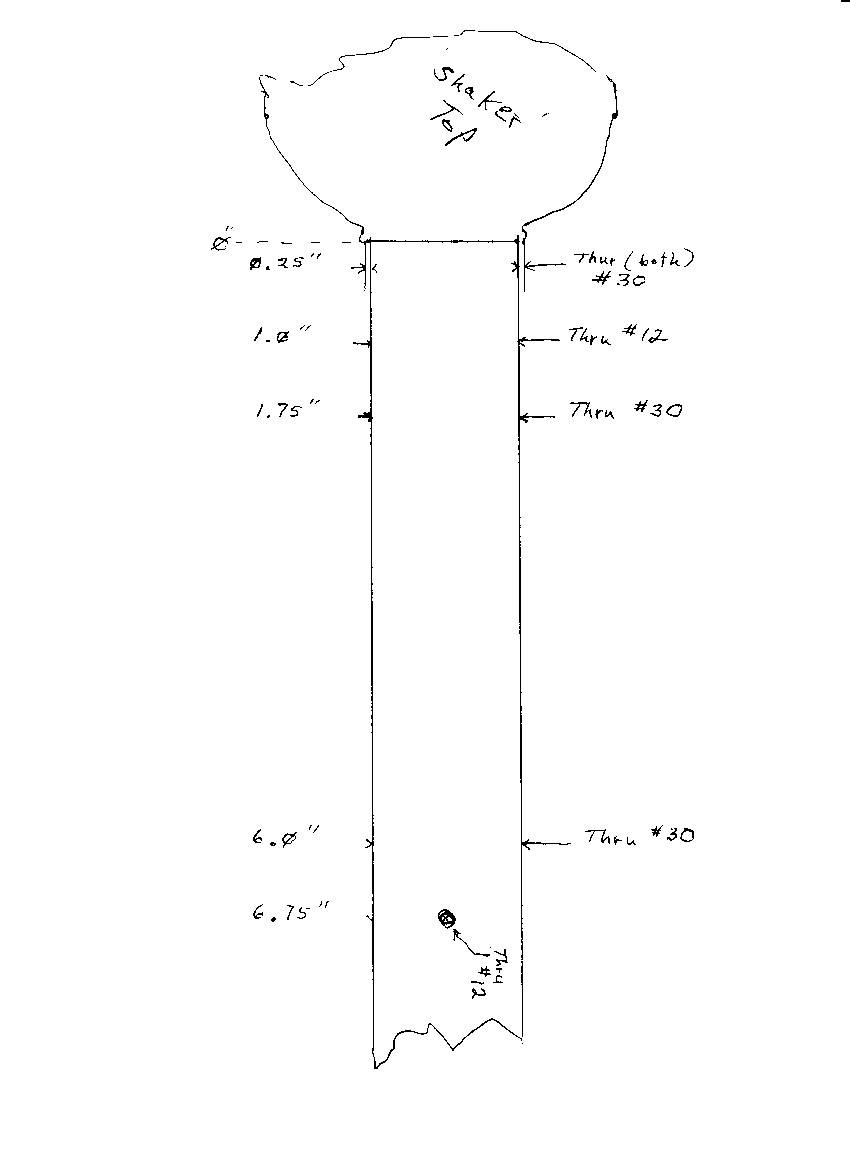
Quote dja wrote: If you could take a close up shot of how you mounted your coils I would appreciate it, may give me some differant idea if I have to change mine, or for when I cut the lower section down height wise. David David, I tried a photo but it doesn't look any different than yours. Here is what I did: 1) I cross-drilled the manifold like the attched drawing. Next I installed a 1.35"/4-40 machine screw with ceramic spacers and a nut through the hole in the heater element. I arranged the spacers so the element is centered. This 'outrigger' just fits inside the barrel of the manifold and won't allow the coils to touch the wall. 2) Next I attached the wires to the element, threaded the wires through the #12 holes at position 6.75", and pulled the element most of the way into position. 3) Then I installed a 1.5"/4-40 cross-bolt through the #30 hole at position 6.0". 4) Working from the 0" end of the tube I installed the mica sheet (came with the element) around the coils, pulled the element (using the wires) against the machine screw I installed at position 6.0". 5) I started another 1.5"/4-40 machine screw in one of the #30 holes at position 1.75". I had to push the mica down a bit more to get the screw started. This screw was next pushed trough a couple of ceramic spacer, through the slot in the heater element, through some more ceramic, out the other side and secured with a silicone o-ring, washer, and nut.. It was easier to do than to explain. OGH
oldgearhead attached the following image:
Edited by oldgearhead on 06/19/2011 4:52 PM No oil on my beans...
|
|
|
|
| dja |
Posted on 06/19/2011 5:09 PM
|
|
1 1/2 Pounder  Posts: 701 Joined: November 07, 2008 |
yea I know, I used stainless steel 4/40 all thread and nylon lock nuts when the nylon chrispy fried it locked em in place. the MICA I didn't figure was worth messing with, but I did add insulation around the outside of the tubes before I pushed it all into the 5 inch tube where it resides now.
I pour Iron and roast Coffee Beans
 If life seems normal your not going fast enough Mario Andrette |
|
|
|
| oldgearhead |
Posted on 06/23/2011 6:37 PM
|
|
1 1/2 Pounder  Posts: 1128 Joined: February 10, 2011 |
Things are moving right along on this project. I only need to receive three parts and drill 3 holes before I start testing. Here is a copy of my final (120 VAC version) bill of material: Brewer_Roaster_BOM + 1 - Bloomfield 8773 (Junk) Coffee Brewer + 1 - Wooden box 30?x18?x13? + 4 - 2.5? Castors + 4 feet of 2? Schedule 40 PVC pipe + 1 - 3 inch Schedule 40 PVC flange + 1 - 3 inch-to-two inch Schedule 40 PVC adapter + 8 feet of 2.5? flex hose + 1 - 2? Schedule 40 PVC ?T?, for bean-evac-to quart jar + 2 - Two inch Schedule 40 PVC couplers + 1 - 1-1/2 HP spa blower (booted) + 6 - ?T? nuts (10-24) + 2 - 1? x 3? piano hinges + 1 lot machine screws, washers, and nuts + 1 - 12?x 1.5? Chrome sink drain extension + 1 - 3.5? Stainless steel cocktail shaker + 1 - Master HAS-043K heat gun element + 1 lot Permatex Red silicone + 1 lot hookup wire + 1 - 14/3 Power cord + 1 - 7.75? piece of 35 mm DIN rail + 10 - 8 mm DIN terminals + 1 - Ice cube relay & socket + 1- Nema 4x Enclosure 9?x 7? x 4? + 1 - Extech VFL PID Controller + 1 - Tyco 50A SSR + 1 - Brew switch (momentary rocker) + 1 - Heater stop switch (momentary N.C. push button) + 1 - Corning bread tube (3.75? x 14?) + 1 - 3? x 3? Aluminum turbo hose coupler + 1 - Zach & Dani chaff screen and baffle-type separator + 3 - Very nice RC parts, custom built by DJA + 1 - Lot of silicone o-rings + 1 - Box of Band-Aids ___ 1 - Tyco 30A circuit breaker ___ 3 - DIN Ground terminals ___ 1 - Green Pilot light ___ 1 - Main switch (maintained rocker) ___ 1 - Dayton 4X796B motor speed controller ___ 1 - Shop vac hose and wand assembly (1.25 inch) for bean-evac-to-quart jar Cheers, OGH Edited by oldgearhead on 06/23/2011 7:01 PM No oil on my beans...
|
|
|
|
| oldgearhead |
Posted on 06/24/2011 10:00 AM
|
|
1 1/2 Pounder  Posts: 1128 Joined: February 10, 2011 |
Quote tra757 wrote: I am working on the next revision of my heat "turbo". Basically recuperation of excess heat the elements throw off. They sit inside an aluminum section 4" in diameter. The outer pipe is 5" and located right at the elements. The T part has a pipe down to the blower inlet. I have been able to raise my input air about 40% with the same power. I will post when its done. Very interesting! I conclude from that information: I should wrap my 1.5" manifold with 'header tape' and then cover that with hot water pipe insulation to boost efficiency...agree? A test I will do: 1) Measure temperature of bare manifol at 500F air temperature. 2) Cover manifold with 'header wrap and measure again at same point. 3) Add pipe insulation and measure again. I actually have a piece of foam pipe insulation. If the 'header tape' is very effective, maybe I could use that. Thanks tra No oil on my beans...
|
|
|
|
| tra757 |
Posted on 06/25/2011 11:48 AM
|
|
Newbie  Posts: 29 Joined: April 30, 2011 |
Quote oldgearhead wrote: Quote tra757 wrote: I am working on the next revision of my heat "turbo". Basically recuperation of excess heat the elements throw off. They sit inside an aluminum section 4" in diameter. The outer pipe is 5" and located right at the elements. The T part has a pipe down to the blower inlet. I have been able to raise my input air about 40% with the same power. I will post when its done. Very interesting! I conclude from that information: I should wrap my 1.5" manifold with 'header tape' and then cover that with hot water pipe insulation to boost efficiency...agree? A test I will do: 1) Measure temperature of bare manifol at 500F air temperature. 2) Cover manifold with 'header wrap and measure again at same point. 3) Add pipe insulation and measure again. I actually have a piece of foam pipe insulation. If the 'header tape' is very effective, maybe I could use that. Thanks tra Here is a video of a new proto of the Heat turbo. I ran it this morning and was getting a bit over 50 degree increase in the input air. http://www.youtub...hgpqc0eIiA There are certainly things that could be done in increase the efficiency but just this simple design works pretty good. Edited by JETROASTER on 06/25/2011 11:50 AM |
|
|
|
| JETROASTER |
Posted on 06/25/2011 11:52 AM
|
|
Administrator  Posts: 1780 Joined: March 06, 2010 |
Hi tra, I made the link clickable, but it appeared to be 'private' Settings?? -Scott |
|
|
|
| tra757 |
Posted on 06/25/2011 1:58 PM
|
|
Newbie  Posts: 29 Joined: April 30, 2011 |
Thanks, I made it public. Tim |
|
|
|
| danw2002 |
Posted on 06/25/2011 2:00 PM
|
|
1/4 Pounder  Posts: 73 Joined: June 12, 2011 |
the thing i was thinking for this was a dual walled vent like is on my Gas water heater, use it just above the heat coils, or even mount the coils inside it, then use my chaff/heat return fan to blow air down from the top along the sides, through this outer pipe and back into my air intake for the heat elements..and make it adjustable to change the heat rise, depending on what you needed the roast system to do....many ideas...so little time....mmm Dan Williams...WHAAAT!?!?!? I have NOT had enough coffee.....
|
|
|
|
| oldgearhead |
Posted on 06/28/2011 8:17 AM
|
|
1 1/2 Pounder  Posts: 1128 Joined: February 10, 2011 |
Well I thought I thought of everything. But of course there is one tiny detail. As I started to assemble the 5 modules into a complete unit I discovered I had no way to attach the manifold thermocouple to the PID. Furthermore, after turning my shop upside-down, I must conclude the only female 'K' connector in Indiana was missing. So, while waiting for the mailman I ordered some 'Mighty Mite' insulation for the manifold and pre-tested the modules: Module 1 (base & blower) - Check Module 2 (Brewer frame, speed control, and SSR) - Check Module 3 (Brewer front & PID) - Check Module 4 (Electrical entrance and control panel) - Check Module 5 (Brewer top, switches, air baffle, and air recycle box) - Check
oldgearhead attached the following image:
Edited by oldgearhead on 06/28/2011 8:20 AM No oil on my beans...
|
|
|
|
| seedlings |
Posted on 06/28/2011 10:47 AM
|
|
1 1/2 Pounder  Posts: 4226 Joined: June 27, 2007 |
30 amps! What size wire did you run from the breaker to the roaster? I used #10 for 240V, 20A. CHAD Roaster: CoffeeAir II 2# DIY air roaster
Grinder: Vintage Grindmaster 500 Brewers: Vintage Cory DCU DCL, Aeropress, Press, Osaka Titanium pourover |
|
|
|
| oldgearhead |
Posted on 06/28/2011 5:40 PM
|
|
1 1/2 Pounder  Posts: 1128 Joined: February 10, 2011 |
Breaker is 40A, wire is 10ga, line cord is 14/3. I can run about anything because the distance is short, the main is a simple QO and it has room for another 80A. I really haven't totally ruled out 220 yet. But the current set-up will probably peak at 21A on 120. OGH IBEW 1225 No oil on my beans...
|
|
|
|
| oldgearhead |
Posted on 06/30/2011 8:54 PM
|
|
1 1/2 Pounder  Posts: 1128 Joined: February 10, 2011 |
Saturday assembly recap page 01: Okay the female TC connector has arrived, each module has been checked out, and its time to put this thing together. I'll start with an image of the base and blower. I shot this with a $900.00 lens that I managed to miss-focus:
oldgearhead attached the following image:
No oil on my beans...
|
|
|
|
| oldgearhead |
Posted on 06/30/2011 8:56 PM
|
|
1 1/2 Pounder  Posts: 1128 Joined: February 10, 2011 |
Saturday assembly recap page 02: Here's the heating manifold. Its all sealed with Permetex Red and fiberglass tape.
oldgearhead attached the following image:
No oil on my beans...
|
|
|
|
| oldgearhead |
Posted on 06/30/2011 8:59 PM
|
|
1 1/2 Pounder  Posts: 1128 Joined: February 10, 2011 |
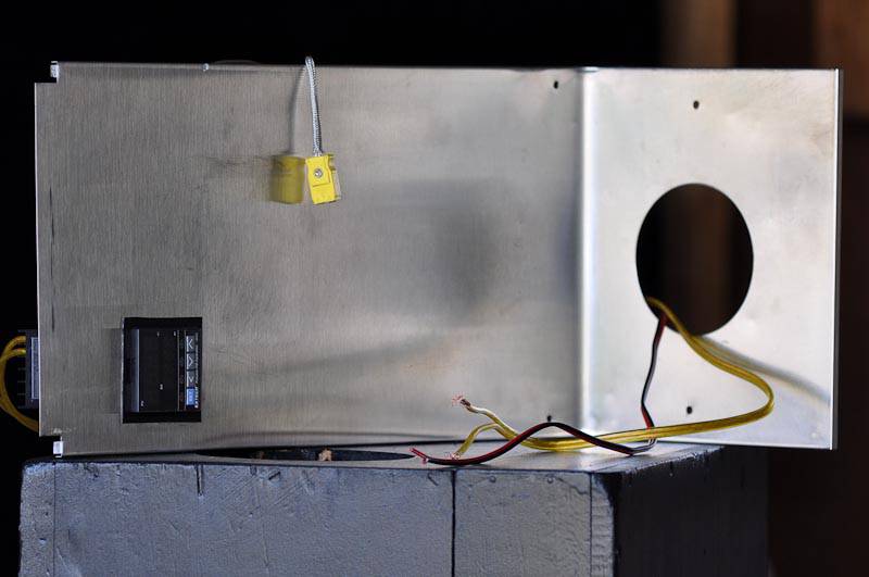
Saturday assembly recap page 03: Here's the front. Notice the female TC connector? Very important item.
oldgearhead attached the following image:
No oil on my beans...
|
|
|
|
| oldgearhead |
Posted on 06/30/2011 9:01 PM
|
|
1 1/2 Pounder  Posts: 1128 Joined: February 10, 2011 |
Saturday assemblt recap page 04: The top with all the control switches and the air control mixing baffle:
oldgearhead attached the following image:
No oil on my beans...
|
|
|
|
| oldgearhead |
Posted on 06/30/2011 9:05 PM
|
|
1 1/2 Pounder  Posts: 1128 Joined: February 10, 2011 |
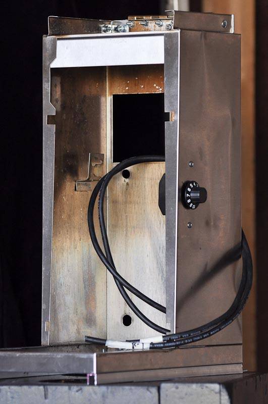
Saturday assembly recap page 05: This is the one-piece frame, back. and sides. See the obsolete Dayton speed control? I hope it works out. My only concern is it has a limited turn-down of only 25% min speed.
oldgearhead attached the following image:
Edited by oldgearhead on 06/30/2011 9:05 PM No oil on my beans...
|
|
|
|
| oldgearhead |
Posted on 06/30/2011 9:08 PM
|
|
1 1/2 Pounder  Posts: 1128 Joined: February 10, 2011 |
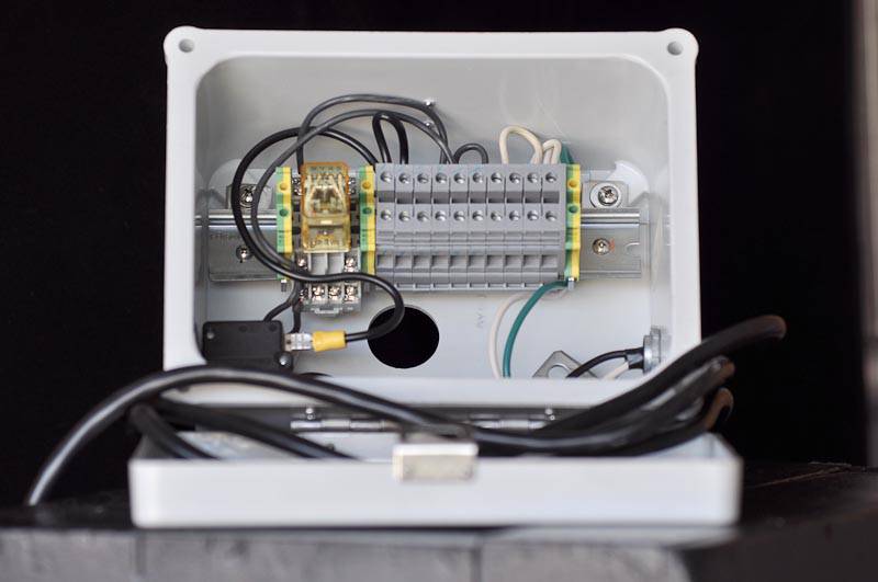
Saturday assembly recap page 06: ..and the control box. If you look real close you will notice I forgot to wire a neutral to the relay. So it didn't quite work the way I planned the first time...
oldgearhead attached the following image:
No oil on my beans...
|
|
|
|
| oldgearhead |
Posted on 06/30/2011 9:11 PM
|
|
1 1/2 Pounder  Posts: 1128 Joined: February 10, 2011 |
Saturday assembly recap page 06: The mailman just dropped off the firewall insulation I ordered. You know, the stuff they use to line the inside of 'funny cars' with. Here is the completed heat manifold.
oldgearhead attached the following image:
No oil on my beans...
|
|
|
|
| greencardigan |
Posted on 06/30/2011 9:34 PM
|
|
1 1/2 Pounder  Posts: 1185 Joined: November 21, 2010 |
Quote oldgearhead wrote: Saturday assembly recap page 06: The mailman just dropped off the firewall insulation I ordered. You know, the stuff they use to line the inside of 'funny cars' with. Here is the completed heat manifold. Great pics. Can I ask how easy it will be to replace your element if it's every required? |
|
|
|
| oldgearhead |
Posted on 06/30/2011 9:48 PM
|
|
1 1/2 Pounder  Posts: 1128 Joined: February 10, 2011 |
Okay I just couldn't wait so I tossed in 400 grams of some Thai 'Hot Boy' beans and turned it on. Here is my list of issues: 1) The manifold TC is worthless (to much air flow maybe?) it reads 345F when the beans are in a 'roaring' first crack. 2) How did I know the beans were in first crack? I got close and started to listen when I received a shower of chaff accompyed by the 'cracking' noise comming from over my head! I checked everything and didn't see anything wrong until I realized the pressure at the top of the RC was actually lifting the brewer top in the air. I've got to tie down the top or add weight or clamps. 3) The Z&D baffle-separator worked well but as David predicted it isn't big enough. That shouldn't be too hard to fix because there is plenty of room in the RC you could even put a cyclone separator in it if you wanted. However, for coffee I think a baffle-separator is just about as effective. 4) It was 96F in the shop this PM so I didn't try to recycle any air. Conclusions: A) 400 grams to first crack in 10 minutes. Full-city in 14 minutes. I don't (intentionally) do dark roasts. B) Current with 120 VAC was 20 amps with heater on 100%. C) The speed control could be a problem. With 400 grams I couldn't turn it down quite far enough for a good 'spout'. I'll try 500 grams next time. D) I guess I need to gring a slot in the RC base for my BMT probe. E) I wonder what it will do if I can seal the top? I'll try to get some video over the weekind. No oil on my beans...
|
|
|
|
| Jump to Forum: |
Powered by PHP-Fusion Copyright © 2024 PHP-Fusion Inc
Released as free software without warranties under GNU Affero GPL v3
Designed with ♥ by NetriXHosted by skpacman


