
Login

Shoutbox
You must login to post a message.
renatoa
07/26/2024 3:49 PM
Bill grubbe and Jk, 
allenb
07/26/2024 5:15 AM
Spiderkw Welcome to HRO!

renatoa
07/24/2024 8:31 AM
ramiroflores and John123,

 ?
?
?renatoa
07/21/2024 1:18 AM
 , Luislobo
renatoa
07/19/2024 11:28 AM
Koepea,
Forum Threads
Newest Threads
Skywalker roaster modsBackground Roast Iss...
Hello from Arkansas
TC4ESP
Green coffee reviews
Hottest Threads
| Skywalker roaster... | [375] |
| TC4ESP | [115] |
| War on Farmers by... | [47] |
| Adventures in flu... | [26] |
| Hello! (soon) Roa... | [17] |
In Memory Of Ginny

Donations
Latest Donations
dmccallum - 10.00
JackH - 25.00
snwcmpr - 10.00
Anonymous - 2.00
Anonymous - 5.00
dmccallum - 10.00
JackH - 25.00
snwcmpr - 10.00
Anonymous - 2.00
Anonymous - 5.00
Users Online
Guests Online: 10
Members Online: 0
Total Members: 8,394
Newest Member: Bill grubbe
Members Online: 0
Total Members: 8,394
Newest Member: Bill grubbe
View Thread
Who is here? 1 guest(s)
Page 2 of 2: 12
|
 My first popcorn mod roaster (vahegan)
|
|
| vahegan |
Posted on 04/06/2014 12:57 AM
|
|
Newbie  Posts: 48 Joined: March 23, 2014 |
Thank you very much, Allen, for tipping me in the right direction. The new roasts are just terrific! |
|
|
|
| allenb |
Posted on 04/06/2014 11:51 AM
|
 Administrator Posts: 3869 Joined: February 23, 2010 |
You're welcome and glad to help. A few years ago, before finding HRO, I was having trouble attaining good results with my roasting and after lots of reading and discussing different profiles with our members I was able to achieve great results. Homeroasters has helped me tremendously with roasting tips and roaster building + controls. Allen 1/2 lb and 1 lb drum, Siemens Sirocco fluidbed, presspot, chemex, cajun biggin brewer from the backwoods of Louisiana
|
|
|
|
| sshanky |
Posted on 05/09/2014 12:59 PM
|
|
Newbie Posts: 10 Joined: May 08, 2014 |
Hi Vahegan, This sounds great! I would love to build one of your designs. I have everything ready to go, and I was just hoping you would share the up-to-date code with the constant temperature increase shown above. I tried downloading and using the code you provide near the beginning of the thread, but I couldn't get it to work, probably because I was using the wrong Nokia5110_graph library? I got a lot of errors related to the 5110. Would you mind pointing me in the right direction to get the same libraries you used? I'm really excited to try to build and use this. Thanks from Phoenix |
|
|
|
| vahegan |
Posted on 05/09/2014 3:16 PM
|
|
Newbie Posts: 48 Joined: March 23, 2014 |
Quote sshanky wrote: I would love to build one of your designs. I have everything ready to go, and I was just hoping you would share the up-to-date code with the constant temperature increase shown above. I tried downloading and using the code you provide near the beginning of the thread, but I couldn't get it to work, probably because I was using the wrong Nokia5110_graph library? I got a lot of errors related to the 5110. Would you mind pointing me in the right direction to get the same libraries you used? Hi! Oh, sorry for that. I forgot to mention that I modified Henning Karsten's library to save up one pin on the Arduino (in my design I have tied chip select to ground, so that the LCD is always selected. I am attaching the new code and the modified library in archived format.
vahegan attached the following files:
|
|
|
|
| sshanky |
Posted on 05/10/2014 2:02 AM
|
|
Newbie Posts: 10 Joined: May 08, 2014 |
Thanks very much! I have put it together on the breadboard and the only thing that is not working is the LCD. I tested the LCD with the example in your modified library using 4 connections (SCE, which I think is chip select, to ground), and it worked. But with the roaster_ramp sketch, using the same pins, it stays blank. One thing I noticed is that the sketch tries to include "LCD_5110_Basic.h", but the library is called "LCD_5110_Graph.h", so I changed this in the roaster_ramp sketch to avoid errors. I've connected LEDs to the circuit to represent the fan and the heat, and they appear to be working (when I press one of the buttons, the fan led lights steady and the heat led blinks. I think that makes sense... I think I just have something odd with the LCD library? Maybe changing the name caused some issues for the script? I wish I were a little better with coding so I could decipher this myself. Thanks for the help... |
|
|
|
| vahegan |
Posted on 05/10/2014 10:21 AM
|
|
Newbie Posts: 48 Joined: March 23, 2014 |
Oh, I see. Initially I used the graphics library as I planned to plot the roast graph pn the screen. Later I abandoned this idea since the screen is small and resolution is low - there was no sense in doing this. After some version I switched to the basic version of the library to save some program memory. Somehow it didn't work as well as the graph version but saved me a couple of kilobytes which was essential. I didn't have much time to find out what was wrong with this conversion or to optimize the code otherwise. I rather decided to spend the time into development of my next version of roaster project and, for the time being, using the code as it is (I had to add screen initializations at each roasting stage to get rid of blank screen issues I was seeing once in a while). I am attaching my modified version of 5110 Basic library, please give it a try and let me know if this works. If not, I'll send an older version of the code which worked with the graph library: in the older version the screen was more stable but the memory was quite tight. Sorry for this mess. This was an experimental project, it was never intended for reproduction. Actually, I did this to gain some experience before I build my a better roaster...
vahegan attached the following file:
|
|
|
|
| allenb |
Posted on 05/10/2014 10:49 AM
|
|
Administrator Posts: 3869 Joined: February 23, 2010 |
Quote vahegan attached the following file: lcd5110_basic.rar [377.65kB / 4 Downloads] Please recommend best program for opening the .RAR file extension. Allen 1/2 lb and 1 lb drum, Siemens Sirocco fluidbed, presspot, chemex, cajun biggin brewer from the backwoods of Louisiana
|
|
|
|
| vahegan |
Posted on 05/10/2014 2:12 PM
|
|
Newbie Posts: 48 Joined: March 23, 2014 |
Quote Please recommend best program for opening the .RAR file extension. Hi Allen, for .RAR you can either use WinRAR or the free 7-Zip |
|
|
|
| sshanky |
Posted on 05/11/2014 2:18 AM
|
|
Newbie Posts: 10 Joined: May 08, 2014 |
Great! That did the trick -- it's working now in principle. I have a display that works and the LEDs work, so the next step is to connect it to the heater and fan. I'll post my progress if anyone is interested. |
|
|
|
| vahegan |
Posted on 05/11/2014 1:40 PM
|
|
Newbie Posts: 48 Joined: March 23, 2014 |
Great! Please do report about your progress! I think you'll have to adjust the PID coefficients depending on blower and heater power in your unit. Well, I noticed that with temperature ramp it is not as sensitive to PID values as compared with the initial code when I was trying to maintain constant temperature levels. Make sure to use an optocoupler when you control the heater triac. Actually, I used a zero-cross optocoupler:  And a darlington transistor to control the fan: 
Edited by vahegan on 05/11/2014 1:49 PM |
|
|
|
| sshanky |
Posted on 05/12/2014 1:34 AM
|
|
Newbie Posts: 10 Joined: May 08, 2014 |
Well, I didn't do too well  I used a solid state relay to control the heat, and it worked well. The fan, however, was a different story. I used a MOSFET, but the fan wouldn't go fast enough. I tested and found only 8v going to the fan, probalby because only 2.3v were coming from the Arduino. Also, it was behaving very erratically -- when I'd reset the arduino, the fan would very briefly go full speed. Also, when I would disconnect a pin from the MOSFET the fan would sometimes go and sometimes stop. I think I need a pulldown resistor? I used a solid state relay to control the heat, and it worked well. The fan, however, was a different story. I used a MOSFET, but the fan wouldn't go fast enough. I tested and found only 8v going to the fan, probalby because only 2.3v were coming from the Arduino. Also, it was behaving very erratically -- when I'd reset the arduino, the fan would very briefly go full speed. Also, when I would disconnect a pin from the MOSFET the fan would sometimes go and sometimes stop. I think I need a pulldown resistor?But the real problem happened when I noticed the 21v power supply was not working properly (I tested it independently with the fan and it woudln't work. It's an old one, so I don't trust it) so I changed it with another one, and while doing that I noticed the arduino was on, even though I had pulled the USB power from it. Then the fan started spinning full speed, and I suspected there might be too much power going somehow back into the Arduino, so I pulled the wire from the MOSFET, noticed it was very hot, and pulled all the power. But now, my Arduino is fried, the green light comes on, and it passes the loopback test, but it won't boot. It was suggested that I might not have the right diode on my motor, and that I should use a resistor between the Arduino and the MOSFET...but maybe a darlington transistor is what I need (have to look that up and learn about it). Here is a sketch of what I did (does not show it, but arduino also connects to ground):  Here's the motor, with diodes already attached:  I will try again with a new one in the next few days. I'm determined to get it working Thanks so much for all your help and encouragement! |
|
|
|
| vahegan |
Posted on 05/12/2014 12:54 PM
|
|
Newbie Posts: 48 Joined: March 23, 2014 |
Can you give the full circuit schematic? I.e. where do you supply power? Do you supply to Arduino the same 21V which you use to power the fan motor? If yes, that is too much for Arduino, the voltage regulator on the board would overheat. It is better to supply the Arduino from a 7V power supply (make sure that the grounds of the Arduino power supply and the motor power supply are connected to each other). What do you mean by "only 2.3v coming from the arduino"? What mosfets do you use? (BTW, you do not need a mosfet to control the Solid State Relay: you can connect it directly between Arduino output and ground, through a resistor). Mosfets require a relative high voltage on the gate (around 10V) to open properly. Arduino can only supply slightly below 5V to the gate. Thus a mosfet would not be fully opened and will be overheating (its drain-source resistance will be high and the mosfet will dissipate too much power). You can either use a Darlington transistor (I used TIP122) or a mosfet designed specifically to operate the gate at logic levels. They have the letter "L" in the name: for example, you can use IRLZ44. Yes, and always install all the power transistors on a proper heatsink, or they'll get hot. If there are several mosfets on one heatsink, use an insulating pad between the transistors and the heatsink or they will short-circuit. |
|
|
|
| sshanky |
Posted on 05/12/2014 2:26 PM
|
|
Newbie Posts: 10 Joined: May 08, 2014 |
I am working on a schematic that I can post. I have taken off the MOSFETs so I have to remember exactly how I did that part. However, I have since learned about the 10v requirement for the ones I used (IRF540N). I ordered some logic level ones, FQU13N06LTU-ND MOSFET N-CH 60V 11A IPAK (based on a recommendation someone gave), but maybe I should instead order the transistor you mentioned. Also, I didn't use the fan power supply for the Arduino -- it was just connected to the computer or a 1.5A phone charger. I have read that you need at least 6v for the Arduino, so maybe that is why the digital outputs didn't make enough voltage. I measured the pin that was controlling the fan MOSFET and it showed 2.3v. It might be that PWM was causing it to show a lower voltage, but it was low even after I changed the code to run the fan at full speed. I have tried running a SSR from the pin directly on a Raspberry Pi once, and there wasn't enough output to turn it on, so I used a MOSFET. I decided to do it the same way here, but I will try next time without one. What do you use as your power supply for the Arduino? Can I use the fan's power supply somehow by easily reducing voltage from 20v to what the Arduino needs, so i don't have to use two power supplies? Thanks! |
|
|
|
| vahegan |
Posted on 05/12/2014 4:24 PM
|
|
Newbie Posts: 48 Joined: March 23, 2014 |
Quote sshanky wrote: I am working on a schematic that I can post. I have taken off the MOSFETs so I have to remember exactly how I did that part. However, I have since learned about the 10v requirement for the ones I used (IRF540N). I ordered some logic level ones, FQU13N06LTU-ND MOSFET N-CH 60V 11A IPAK (based on a recommendation someone gave), but maybe I should instead order the transistor you mentioned. Also, I didn't use the fan power supply for the Arduino -- it was just connected to the computer or a 1.5A phone charger. I have read that you need at least 6v for the Arduino, so maybe that is why the digital outputs didn't make enough voltage. I measured the pin that was controlling the fan MOSFET and it showed 2.3v. It might be that PWM was causing it to show a lower voltage, but it was low even after I changed the code to run the fan at full speed. I have tried running a SSR from the pin directly on a Raspberry Pi once, and there wasn't enough output to turn it on, so I used a MOSFET. I decided to do it the same way here, but I will try next time without one. What do you use as your power supply for the Arduino? Can I use the fan's power supply somehow by easily reducing voltage from 20v to what the Arduino needs, so i don't have to use two power supplies? Thanks! FQU13N06LTU is OK to use, except it will be difficult to mount it on a heatsink, it is designed to be soldered on the PCB by the tab, so that the heat is dissipated by the copper layer. Well, at 115mOhm drain-source resistance, it may be able to work without a heatsink at currents around 1A, give it a try. Raspberry PI works from 3.3V and it may, indeed, be insufficient to drive an SSR. Arduino works from 5V and its adequate for securely controlling the SSR. The small output voltage you have measured - this is due to incorrect measurement, You can't measure a PWM signal voltage with a multimeter, you need an oscilloscope for this. In order to reduce the voltage from 20V to some 7V for Arduino you can use a small DC-DC converter. I like the switchinf DC-DC units based on LM2596, I usually buy 10pcs (at that quantity you can get each one for less than $1 at eBay) and use them in all my projects. But for my roaster, I wanted to fit everyting in the popper case and therefore I made a power supply based on the IR2155 chip, 2 FETs and a transformer - I made an extra secondary winding on the transformer just to supply the Arduino. |
|
|
|
| sshanky |
Posted on 05/14/2014 12:38 PM
|
|
Newbie Posts: 10 Joined: May 08, 2014 |
OK, I've gotten my new Uno (with a replaceable chip this time in case I break something!), and I bought some of the (really cool) LM2596 units to run the Arduino off the fan power supply. Everything is working (including the solid state relay directly from the Arduino) but I'm still waiting for my logic-level MOSFETs which should be arriving today and then I can make the whole thing work. I was thinking that rather than have the fan start at 80%, perhaps it would be better to start it at 100%, and then drop it when necessary (i.e. when the heat is not enough to keep the temp climbing). By that point, the beans will be drier and will be easier to blow around. This will enable more beans to be roasted. I'll let you know how I go tomorrow! I'm almost out of roasted beans |
|
|
|
| vahegan |
Posted on 05/14/2014 3:13 PM
|
|
Newbie Posts: 48 Joined: March 23, 2014 |
Quote sshanky wrote: I was thinking that rather than have the fan start at 80%, perhaps it would be better to start it at 100%, and then drop it when necessary (i.e. when the heat is not enough to keep the temp climbing). By that point, the beans will be drier and will be easier to blow around. This will enable more beans to be roasted. I'll let you know how I go tomorrow! I'm almost out of roasted beans There are a couple of factors based on which I choose the fan speed. One is, that too much a flow can make the beans airborn, and the second - indeed - in my setup, at full fan speed, the temperature never gets over 190C. In my case 80% speed is more than adequate. Actually, I set it to 100% immediately at the cooling stage, and the beans often fly out of the roaster by that time. I was thinking to modify the code to wait some 10 seconds before turning the fan to full speed - when they cool down a bit, they are not flown out as easily. |
|
|
|
| sshanky |
Posted on 05/15/2014 3:10 AM
|
|
Newbie Posts: 10 Joined: May 08, 2014 |
Well, I connected the new logic-level MOSFET and it worked! I soldered some speaker wire to the three terminals to help dissipate the heat, as it's really tiny compared to the other MOSFETs I had. There was still an unexpected behavior -- when I start roasting, the fan spins at the programmed speed, but when I press reset, it usually (but not always) speeds up to full speed for about a second before stopping. Here's a short video of stage 2: https://www.youtube.com/watch?v=R-HcgVB0v5U Notice the coffee beans are just starting to spin around on their own at this point. Fan speed here is 200. Here is a short video of the cooling: https://www.youtube.com/watch?v=fd-9hifJsvU Also, here's a chart of my roast:  It heated up a bit too fast at the beginning, but then couldn't keep up at the end. I did raise the fan speed a bit: {" Decaf ",152,120,190,180,225,270,100,200,250,200,45} Below 200 and the coffee didnt' really spin. Or perhaps I put too much in. I'll have to bring it down slightly. The problem is at the beginning, when the beans are heavier, they don't move much. At 200, I had to help them move a bit until they got lighter. Do you mind a few questions? I was wondering what the "Finalize" stage is for -- it seems like 50 seconds of full power, but not sure exactly? I roasted decaf, and didn't get to first crack, so I was happy with the extra time... Second, what is the pin A7 ("A7 AIN Fan voltage") for? I didn't use it. This is great...I am excited to try the coffee in the morning. I'll let you know how it tastes. |
|
|
|
| vahegan |
Posted on 05/16/2014 6:25 AM
|
|
Newbie Posts: 48 Joined: March 23, 2014 |
Well done! Very nice to see a working copy of my roaster! As for the FAN - pull down the FET gate to ground by some 5.1k resistor or something similar to that, so that the FET is closed whenever there is no voltage applied to the gate. The "Finalize" stage - I added this stage when I changed the software to a temperature ramp at a given rise rate. My heater also wasn't getting to the maximum temperature setting at the peak, just before cooling, so I added some idle time to let it heat to the max setting. There could be a more beautiful solution to this problem but I wanted a quick solution, and it worked, and then I was too lazy to change since I am now working on a completely new design, and my popper roaster will only be a backup solution. The A7 pin is connected to ADC. I was planning to measure the voltage applied to the FAN motor (with a voltage divider, of course) as feedback on the actual motor speed. But that didn't work at once, and then I abandoned the idea - you can reuse this pin for whatever you want. |
|
|
|
| sshanky |
Posted on 05/19/2014 2:32 PM
|
|
Newbie Posts: 10 Joined: May 08, 2014 |
I did some tweaking and tried again. This time, I added some fan speed values to the profile array so I could reduce the fan speed in later stages. It worked fairly well! The first time I reduced the fan a bit too much, and I had to lightly tap the roaster to keep the beans moving, but the power stayed under 100%. Also, it was at the right temperature before the 50-second finalize stage, and they burned a bit. Second try, I increased speeds a bit, and probably a bit too high, and shortened the finalize stage to 5 seconds to see if it would help. Here is the chart: After Stage 3 (at the beginning of Finalize), the Thermocouple reading became very erratic and the roaster stopped, so I restarted it immediately to cool the beans (with heater disconnected). You can see in the chart how often the thermocouple went to zero. I can't figure out what is causing this behavior. Sometimes it happens at the beginning of the profile, and the heat stops (is there a way I can prevent the power from cutting to zero whenever the thermocouple returns a zero?). Other times, the thermocouple performs very well. I wonder if complicated thermocouples are worth it -- I would rather use a simple temp sensor but they don't seem to be rated to temps this high. |
|
|
|
| sshanky |
Posted on 05/22/2014 12:58 AM
|
|
Newbie Posts: 10 Joined: May 08, 2014 |
Just did a great roast: I think I have it tweaked pretty well now. The unit can keep the temperature required, following the profile pretty well. I just have a little dip at about 200 seconds where the correction in heat is a bit too strong. I am not sure how to fix that. I'm sure it's related to the P setting but I still have to learn more about PID stuff. I think the thermocouple issue I was having was related to a ground connection; it's not happening any more since I changed my ground. |
|
|
|
| cwood |
Posted on 08/18/2014 12:23 PM
|
|
Newbie Posts: 1 Joined: August 12, 2014 |
OP - I'm trying to duplicate your efforts but am completely new to Arduino programming, and as a result I can't resolve errors that occur when compiling. Some of the issues have been with the MAX6675 library, e.g. Code Download source 'output' was not declared in this scope Can you upload an archive with the files and libraries you have that will allow it to compile easily? I'm pretty confident that if I can get that far, I can build the rest of it to operational condition. Thanks! |
|
|
|
| Black Window |
Posted on 08/22/2014 12:54 PM
|
|
Newbie Posts: 1 Joined: August 19, 2014 |
Hi,I'm sorry to have an off-topic question but here I go... I have the same popcorn maker and it stopped working properly.It doesn't pump air from below anymore.Have you encountered the same problem? Or can you give me any advice? I have looked inside it and there doesn't seem to be anything wrong. Sorry to bother,but you're the only person I could find on the internet that has the same device. |
|
|
|
| Waldguy |
Posted on 03/24/2024 12:04 PM
|
|
Newbie Posts: 1 Joined: July 25, 2022 |
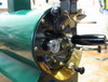
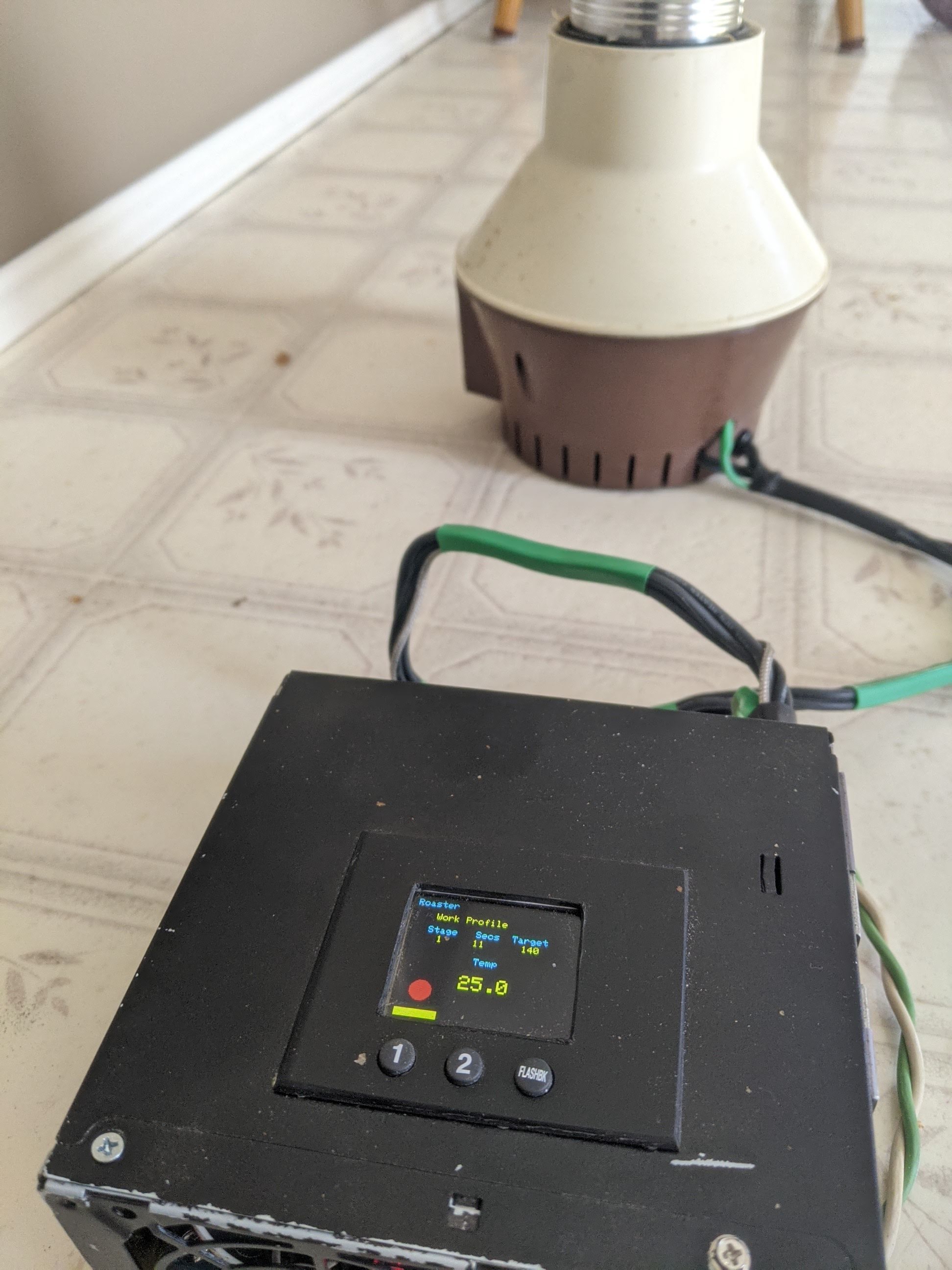
Thank you to vahegan for the amazing code of a decade ago, and detailed instructions. Although no pictures were available any longer, I've been using this thread as the absolute guide for my own project. I'm not smart enough to make my own transformer, so I just bought a 24volt module. I fit the IC stuff in an ATX power box with 7805 step down, BTA16 TRIAC and a TFT display, modifying the code accordingly. I have a minor glitch where the roaster starts by itself when moving it, or just attaching the USB cord, but the third button quickly resets everything. I'm working on the roast profiles, pid, ramp, and fan speed, but I've already enjoyed some amazing cups.
Waldguy attached the following image:
|
|
|
|

Page 2 of 2: 12
| Jump to Forum: |
Powered by PHP-Fusion Copyright © 2024 PHP-Fusion Inc
Released as free software without warranties under GNU Affero GPL v3
Designed with ♥ by NetriXHosted by skpacman