
Login

Shoutbox
You must login to post a message.
renatoa
07/26/2024 3:49 PM
Bill grubbe and Jk, 
allenb
07/26/2024 5:15 AM
Spiderkw Welcome to HRO!

renatoa
07/24/2024 8:31 AM
ramiroflores and John123,

 ?
?
?renatoa
07/21/2024 1:18 AM
 , Luislobo
renatoa
07/19/2024 11:28 AM
Koepea,
Forum Threads
Newest Threads
Background Roast Iss...Skywalker roaster mods
Hello from Arkansas
TC4ESP
Green coffee reviews
Hottest Threads
| Skywalker roaster... | [374] |
| TC4ESP | [115] |
| War on Farmers by... | [47] |
| Adventures in flu... | [26] |
| Hello! (soon) Roa... | [17] |
In Memory Of Ginny

Donations
Latest Donations
dmccallum - 10.00
JackH - 25.00
snwcmpr - 10.00
Anonymous - 2.00
Anonymous - 5.00
dmccallum - 10.00
JackH - 25.00
snwcmpr - 10.00
Anonymous - 2.00
Anonymous - 5.00
Users Online
Guests Online: 5
Members Online: 0
Total Members: 8,393
Newest Member: Bill grubbe
Members Online: 0
Total Members: 8,393
Newest Member: Bill grubbe
View Thread
Who is here? 1 guest(s)
 Low Cost Presto PopLite and Chaff Collector Mods
|
|
| ChicagoJohn |
Posted on 07/13/2015 3:27 PM
|
 Pounder  Posts: 513 Joined: June 15, 2015 |
 After using the modifications I posted in this forum previously, I realized that I wasn't actually using some of the "features" I thought I would need. Because I have an untouched, unopened Presto PopLite and some spare parts, I decided to do a final project intended to produce a fully functional small batch device with ability to replicate any prescribed profile but with minimal cost and easiest construction. I will be doing this in this thread in a series of posts. All will provide step-by-step illustration of the process I am using. Hopefully this will help to spark ideas you will come up with in your own projects. The first "installment" today will be how to construct a passive chaff collector that utilizes two cans and does not require the base of another PopLite Popper. So you can make this without a second popper. They say a picture is worth 1000 words, and I'm attaching 10 of them and they should be self-explanatory. I did discover that the larger can does not fit into the PopLite top with its rim on it. I decided to resolve this simply by cutting slots at 90 degree angles as shown in one of the pictures - "distortion slots" that allow the base of the larger can to be distorted into an oval that will fit nicely into the opening of the base. You just press the sides together to bend it a little. The other thing I will say is that had I been making this for me I would not have included another window in the smaller can. If you have a thermocouple positioned in the roasting chamber off to the side so it's not in the hot air and if you listen for 1C, and go by a prescribed time temperature protocol, I have found I never bother to look in on the beans. So I never use the window. But I put it in this example in case someone feels they need it. They really won't, though. So you can just leave the bottom of the small can as is. In the next installment, I will have step-by-step illustrations of how to modify the PopLite heating and blower functions with lots of labeled pictures. Subsequent installments will show how to construct the controls for roasting; much simpler than the Mod II I posted previously but equally functional. Please let me know if you require clarification on any of the attached images.
ChicagoJohn attached the following images:


Edited by ginny on 07/29/2015 12:47 PM |
|
|
|
| ChicagoJohn |
Posted on 07/13/2015 3:59 PM
|
|
Pounder Posts: 513 Joined: June 15, 2015 |
Three more images that may be of help in understanding how this PCC goes together. If you try it, remember that you have to press the base together to form an oval to fit it into the yellow top of the popper. That's why you have to cut the "distortion channels" as shown.
ChicagoJohn attached the following images:


|
|
|
|
| allenb |
Posted on 07/13/2015 8:59 PM
|
 Administrator Posts: 3869 Joined: February 23, 2010 |
I'm really glad to see more popper roaster modding options and your detailed instructions are excellent. Keep the posts and photos coming! Allen 1/2 lb and 1 lb drum, Siemens Sirocco fluidbed, presspot, chemex, cajun biggin brewer from the backwoods of Louisiana
|
|
|
|
| ChicagoJohn |
Posted on 07/14/2015 7:06 AM
|
|
Pounder Posts: 513 Joined: June 15, 2015 |
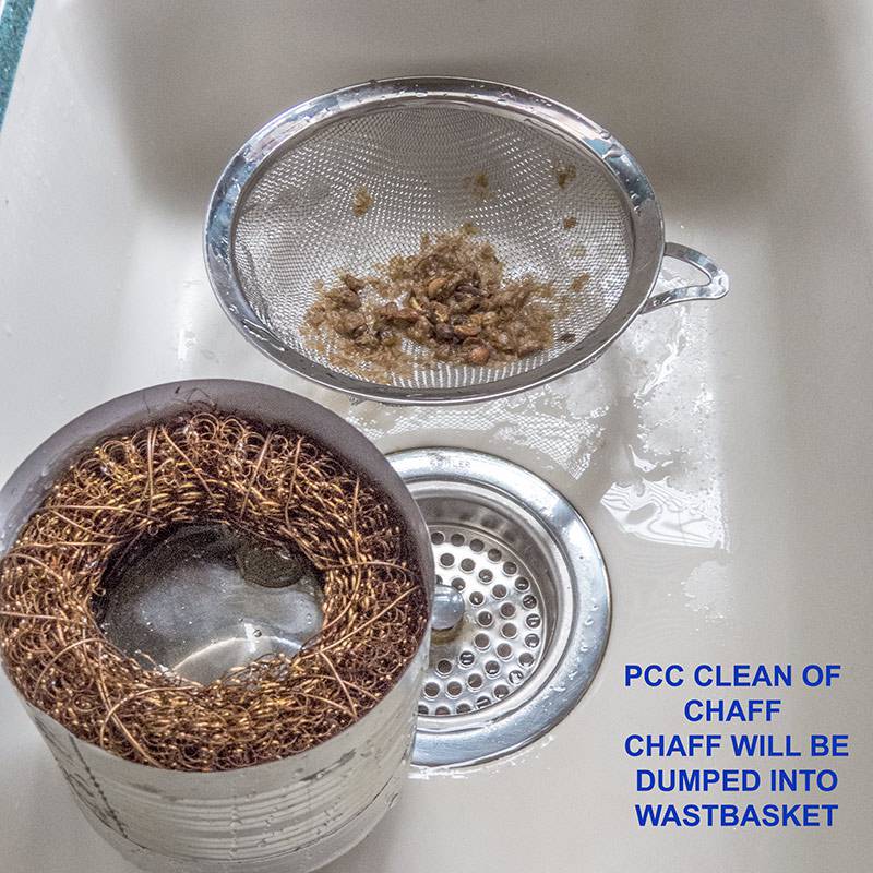
Thanks, Allen. My objective is a device that is capable of reproducible, controlled results on a variety of profiles for purposes of controlled experimentation using small batches, but at the same time one that can be safely and easily built and operated without concern for chaff emissions or with cool-down, and at the lowest possible cost (under $50 total). I've found that elimination of the need for stirring or other operator mixing input is an important design element, and that has been accomplished using the funnel insert to significantly increase the roasting chamber wall angle. At this time, I believe I'm far enough down the learning curve to accomplish these goals in this final build, but the proof will be in the pudding  PS -- I neglected to mention that for this 2nd PCC design, the only part that can be disassembled is the copper mesh filter ring. After the 2 minute in-situ cooling, the PCC is barely warm and can be taken off by hand to empty the cool beans from the popper chamber. I think the best way of cleaning after use (and I think three batches can be done before cleaning), will be to pour water with a drop of dish detergent through the copper filter, swirl it around, then remove and rinse out the copper mesh filter and dump the water and chaff into a mesh sieve in the sink such as you would use for cooking, rinsing the inside of the chamber several times into that sieve. The wet chaff remaining on the strainer can then be dumped into the garbage can. I think the drop of detergent will help in wetting out the chaff during this process and once wet, it won't fly around in the air. Thanks for the kind words Allen; much appreciated! |
|
|
|
| JackH |
Posted on 07/17/2015 6:39 PM
|
 Administrator Posts: 1809 Joined: May 10, 2011 |
Great work John! I really like the chaff collector.
---Jack
KKTO Roaster. |
|
|
|
| ChicagoJohn |
Posted on 07/28/2015 8:04 AM
|
|
Pounder Posts: 513 Joined: June 15, 2015 |
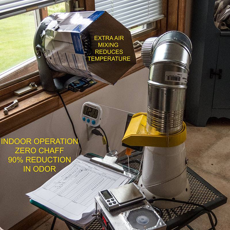
Quote Thanks Jack.... Most of the parts for the low-cost modification have arrived, and I?ll be starting this project description soon. But first, as a follow-up to the cheaper version of the passive chaff collector (PCC) described above in this thread, I have found the need for an improvement. I want to use this roaster in our kitchen with zero chaff and negligible odor. The cheap PCC leaks both chaff and exhaust gas, due to a gap as shown in one of the images attached, and I decided to make a gasket to seal it to the yellow top of the popper. I first covered the opening with heavy-duty aluminum foil that had been coated with spray on-adhesive. I added pieces of foil until the entire surface that would be exposed to the gasket material was covered. I positioned the PCC (squeezed into an oval so it will fit) and marked the front location with black line. Then I liberally applied 100% silicone RTV to the contact surface on the PCC and placed it on the popper top with heavy books holding it down, letting the RTV material cure overnight formed to the aluminum foil under it. To remove it, I ran the popper with no beans in it for about 10 minutes with the coil voltage set to 50 VAC to heat the assembly to around 200F / 90C. At this temperature the spray-on adhesive bonding the foil to the popper top melts, and the PCC will just lift off easily without placing any stress on the cured gasket material. After using a shears to trim off the gasket material that oozed beyond the PCC, I then applied aluminum tape around the base of the can extending over the RTV to form the final shape that I wanted to seal the gap. I did a couple roasts with some cheap Ethiopian Sidamo grade 2 (which I will never buy again) and got zero chaff and using the small window fan shown, an estimated reduction in odor of around 90% versus roasting without the fan. The gasket was effective in blocking exhaust leakage. The fan shroud and placement of the exhaust conduit allows for sufficient temperature reduction via introduction and mixing of ambient air so that fan will tolerate the temperature of the air mixture. (Note that there cannot be a flavor effect on the beans because they are upstream in the bottom of the chamber.) I also attached some photos of how easy it is to clean the PCC and dispose of chaff. Because of these cheap beans, I did get a few small ones in the PCC along with the chaff. So my next project will be to document construction of the low-cost modification for this popper, which should also include functional improvements, and after that will be an attempt at an odor suppressor based upon activated carbon granules for use during winter months when I can?t open a window. I?ll just put all of this here in this thread in case anyone wants to try it.
ChicagoJohn attached the following images:


Edited by ChicagoJohn on 07/28/2015 8:17 AM |
|
|
|
| ginny |
Posted on 07/28/2015 3:25 PM
|
 Founder Posts: 3476 Joined: October 24, 2005 |
I may need to get out the box of poppers I have and make one of these very cool roasters... I love the chaff collector John. you have done a super detailed build for us, thank you very much... I gotta do this. ginny 
Edited by ginny on 07/29/2015 12:42 PM |
|
|
|
| ChicagoJohn |
Posted on 07/28/2015 3:41 PM
|
|
Pounder Posts: 513 Joined: June 15, 2015 |
Quote ginny wrote: I may need to get out the box of poppers I have and make one of these very cool roasters... I love the chaff collector John. you have done a super detailed build for us, thank you very much... I gotta do ths. ginny Thanks, ginny. But if you are at all a procrastinator, I'd advise you to wait until I'm able to post the details of the entire low-cost modification; which are awaiting a few components for photos. For anyone who is interested in small, 90 gm roasts with controlled profiles for experimental purposes, I think this will be of interest. Since I'm consuming 30 gm per day (excluding failed experiments), it will probably be all I'll ever need I will try to get started on the popper modification tomorrow. |
|
|
|
| allenb |
Posted on 07/28/2015 7:08 PM
|
|
Administrator Posts: 3869 Joined: February 23, 2010 |
Great detailed post of what looks to be a very versatile popper sample roaster. I'm most likely going to follow Gin's lead and throw one together for small sampling roasts and for just giving several of my green purchases a try without having to do a large roast. Keep the posts coming! Allen 1/2 lb and 1 lb drum, Siemens Sirocco fluidbed, presspot, chemex, cajun biggin brewer from the backwoods of Louisiana
|
|
|
|
| ChicagoJohn |
Posted on 07/29/2015 4:55 PM
|
|
Pounder Posts: 513 Joined: June 15, 2015 |
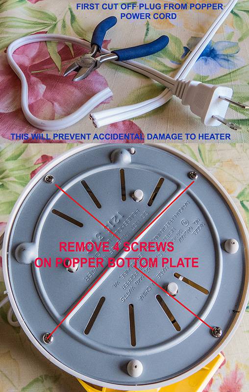
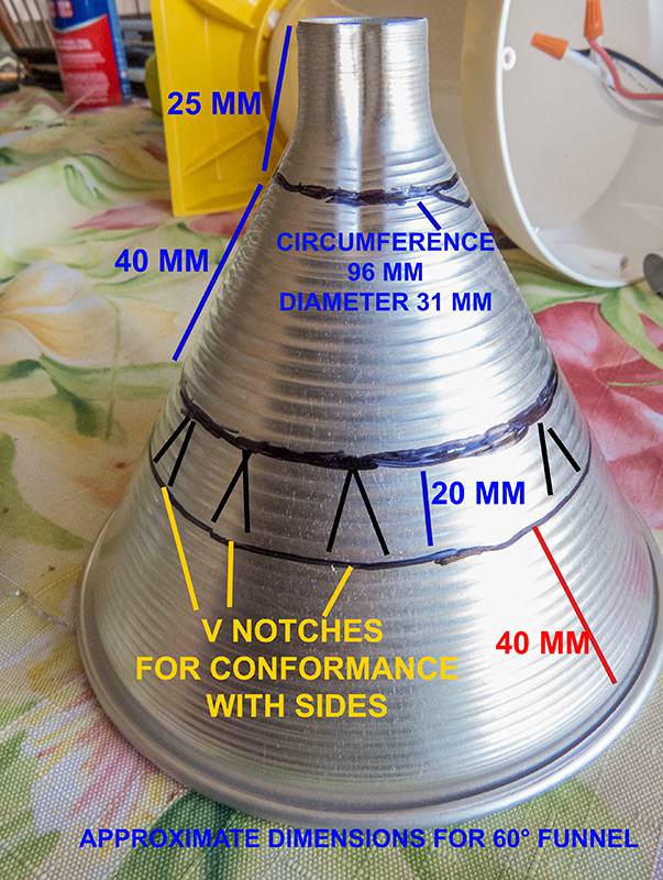
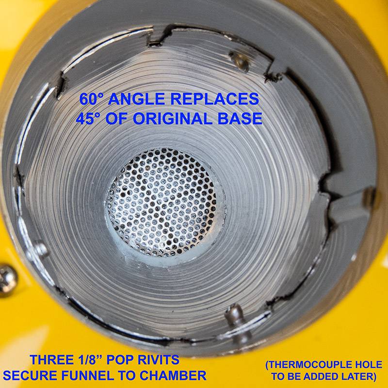
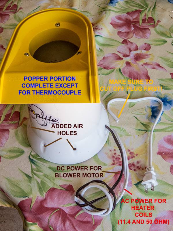
This will cover the modification of a Presto PopLite 04820. Construction of the control box will be discussed in a subsequent post or posts. As a first step, I highly recommend that you cut off the plug on the popper you plan to modify. Should you, or anyone else, accidently plug this into a receptacle after disconnecting the blower as covered here, at a minimum you will ruin the blower and fry the fuse link in the heater portion. In other words, the best case scenario would by you will be purchasing a new popper. I am quite familiar with this from personal experience. Therefore, I highly recommend that you cut off the plug on the popper as your first step in the modification. The attached photos should serve to illustrate this narrative, but please ask if anything is unclear. This modification includes the following: (1) separation of power to heating coils and to the blower motor, (2) removal of the rectifier from the blower motor for subsequent reassembly in the control box, (3) addition of a 60? angle of repose side wall to the roasting chamber superimposed upon the 45? base provided for making popcorn. The first operation allows for fully separate control of the blower motor and heating elements. While this is intended to increase control in the roasting process, it can also result in catastrophic failure if the heaters are ever operated without the blower motor on. The control box is designed to make this virtually impossible (since I managed to cause this to happen twice in previous builds, I discovered that no matter how smart I think I am, I need this to be foolproof, or as close to foolproof as possible.) The second operation would not be required if one were to bring 24VAC from the transformer to the existing AC inputs to the full wave diode bridge rectifier. The reasons I think it is better moved to the control box are (a) the diodes are not very high amp rated and in the event they eventually fail, it will be much easier to swap out a 4A rated bridge (available for around $1) in the control box. The more significant reason, however, (b) is that I would like to have some cooling for the heat sink on the variable power controller that operates the heating coils. This requires 12VDC which will very easy to make from the 24VDC that the rectifier will provide. (This is what I did in a previous project described in another thread, but this time instead of using a 4A bridge, I?ll just use the existing one but move it.) I think the third change ? increasing the wall angle ? is important in eliminating the need to stir roasts in the 100 gm range, or otherwise tilt or tip the popper to achieve good action of the beans before they?ve dried out and decreased in density. Kernels of popcorn are small and pretty spherical and their mobility in a 45? wall roasting chamber would probably be great. Coffee beans are highly acicular and seem to be more likely to form ?log jams? due to the combined effect of their initial weight and their shapes. The passive chaff collector designs covered previously preclude stirring (though that capability could be added), and a design that obviates the need to do this seems easier and also capable of eliminating one more variable. The modification in electricals described is specific to the PopLite 04820, available on Amazon for around $18 including shipping. Don?t make any assumptions regarding applicability of the information provided to other makes and models. This model contains two heating coils that operate in parallel. The main coil measures about 11.4 ohms. The secondary coil is about 50 ohms. The reason for the secondary coil is to drop the AC voltage that goes to the rectifier that produces the DC voltage for the blower motor. In operation, the AC voltage at the AC nodes on the bridge rectifier are about 20 VAC. This approximate level of AC voltage can be supplied to the bridge with a 24VAC transformer that, in this case, transforms 120VAC line voltage to 24VAC. When this reduced voltage goes through the diode bridge rectifier, the output is unregulated roughly 20V pulsed DC. Since the line frequency is 60 Hz, the full wave output is 120 Hz. So I believe the motor may run a little faster than it did in the popcorn popper, but I think it is probably operating at an acceptable voltage level. The 24VAC input has been used by many others in this kind of application without reports of motor failures. Simple DC motors are frequently run from unregulated power (no reservoir capacitor). With the use of the transformer, the 50 ohm resistive load can simply be used to generate heat. Thus the lead that previously went to the bridge operating the motor now simply goes directly to the common/return connection along with the connection from the main 11.4 ohm heating coil. The two coils then form a simple parallel resistor network which calculates to about 9.4 ohms (1/11.4 + 1/50)^-1. At 120VAC, this would be just over 1.5KW of power. I have been running my existing unit at under 85VAC (770 W), and it seems to do just find for my roasting preferences (on the light side), but I?ve also done a few up to 230?C / 446?F, and everything seemed to go OK? except for the flavor of the coffee  As shown, you can complete the wiring changes without any disassembly other than taking off the bottom plate and transferring wires using the wire nuts. Leave the ?hot wire? connection to the coils as is, add the wire that was going to the blower motor to the return/common wires, snip off the diodes and save them as shown, and solder wires onto the + and ? leads for the motor (making sure you know which is which when you connect them in the control box later), and that?s about it for the wiring changes. The brown lamp cord I used has a ridge on the common wire, so I used that for the negative lead and the other wire for the positive lead on the motor. I think the pictures covering how I installed the 60? funnel wall (Ace Hardware in the Housewares section for around $4) is probably clear enough, but let me know if it isn?t. I probably won?t have the rest of the parts to finish the control box for a couple of weeks because I was trying to keep everything as cheap as possible and some of the parts are shipping from China and that can take a while. But I will try to do one or two interim posts showing what I am able to do with the parts I already have.
ChicagoJohn attached the following images:


Edited by ChicagoJohn on 07/29/2015 5:04 PM |
|
|
|
| ChicagoJohn |
Posted on 07/30/2015 10:25 AM
|
|
Pounder Posts: 513 Joined: June 15, 2015 |
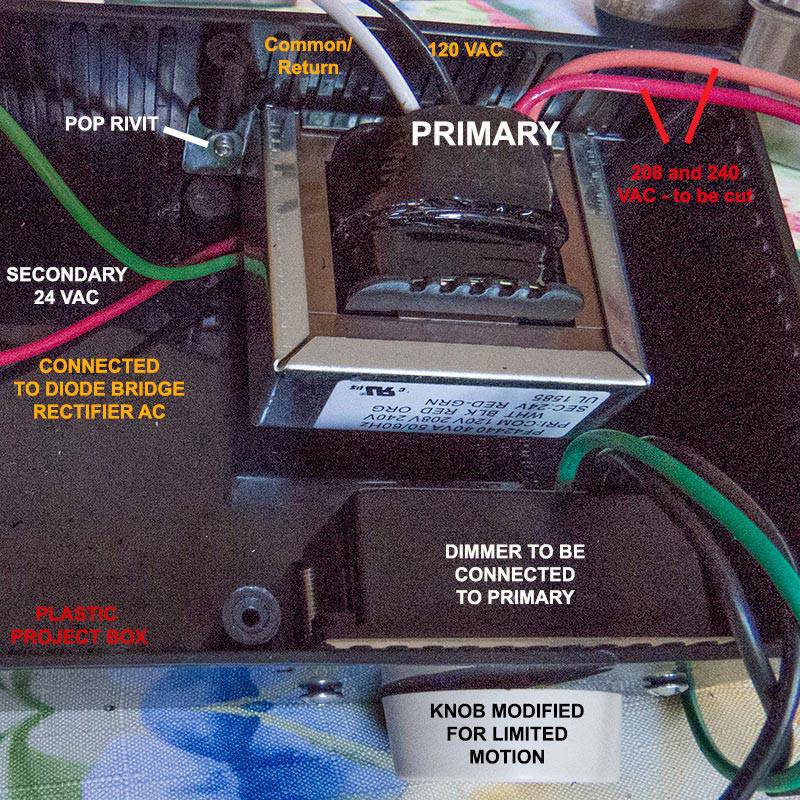
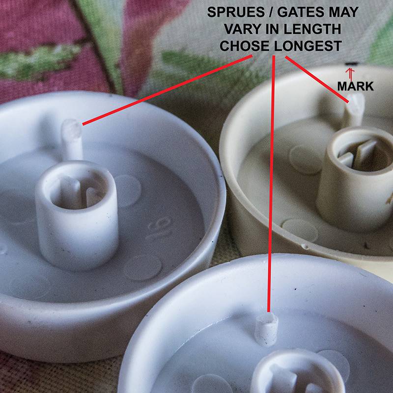
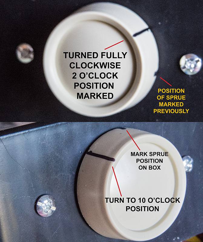
To power the blower, I used a transformer (Packard PF42240 24VAC/40VA) bought for $11 at Home Depot Online with free shipping to the store. It has options for 208 and 240 VAC primary voltage (Red and Orange) I?ll be clipping off, using the 120 VAC (Black) hot wire and the white common/return. The secondary wires are red and green as shown in the photo. These will go to the re-positioned diode bridge rectifier AC nodes, position irrelevant to produce the unregulated DC power to the motor. A 7812 regulator will be used to supply 12VDC to a small fan for the heat sink of the heater power controller. The project box is Hammond 1591ESBK ABS from Amazon for $7.45 with free shipping. I think plastic is safer than metal and definitely much easier to fabricate. While I seldom have used the blower motor control on my first two builds, recently I got a pound of grade 2 beans that were highly variable in size with several broken beans, peaberries, and general size variation. This resulted in about a dozen being ejected into the PCC during the roast, and I felt that if I were to encounter anything like this in the future (hopefully not) lower blower velocity might be nice to have as an option. So I picked up the cheapest, single-pole dimmer they had at Home Depot for around $5. From my experience, I think it is very important to insure that the blower is on anytime heating is powered. With that in mind, I got a dimmer that does not have a push ON-OFF function, only a detent when turned fully counter clockwise. The images show how to install a metal ?stop? that will cause the residual sprue within the knob to stop before turning back to ?OFF?. The method shown will give a range of voltage approximately +/- 20% of the original popper with the lowest speed being sufficient to prevent immediate damage from heater operation. The wiring of the power switches will insure that heaters cannot be operated without setting to ON the switch that operates the blower; switching the blower OFF switches the heaters to OFF as well although with blower ON the heater may be either ON or OFF.
ChicagoJohn attached the following images:


|
|
|
|
| ChicagoJohn |
Posted on 07/31/2015 9:29 AM
|
|
Pounder Posts: 513 Joined: June 15, 2015 |
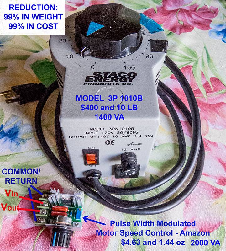
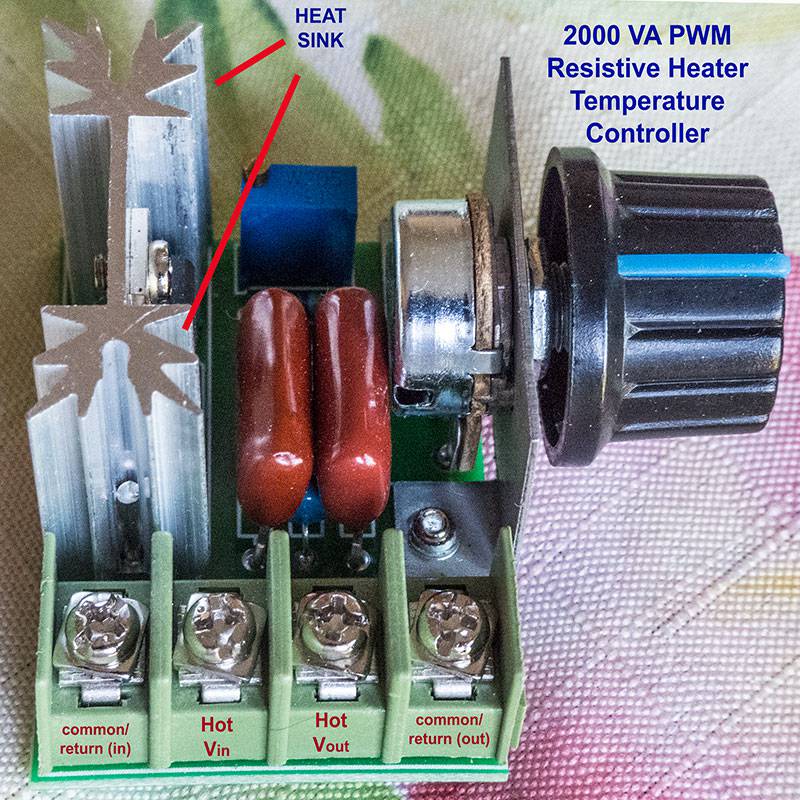
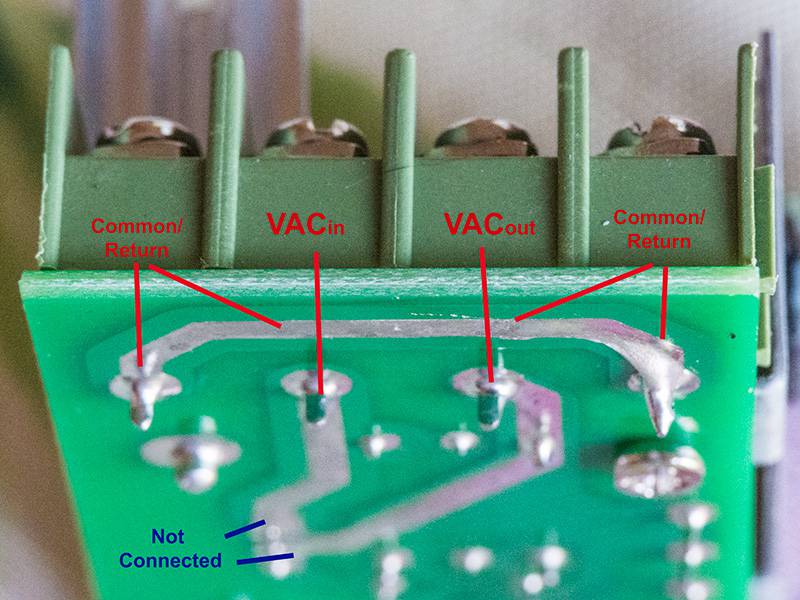
This post covers the controller for the heating coils. I thought I?d include a comparison of where I started out, with a lab variac, to where I?m ending up for now with pulse width modulator that is 1% the weight and 1% the cost, yet with over 40% more power capacity. Technology is definitely changing, and I think Ray Kurzweil?s exponential calculations seem right. Twenty years ago my wife was doing crystalline glazed porcelains and needed precise time-temperature profiles, and I used a Pentium III and a BASIC program with POKE commands for control of a ? degree stepper motor with TTL through a transistor circuit I built to turn a rheostat that in turn changed the frequency of a zero-crossover solid state relay in the basement operating 60 amp 240VAC coils in her kiln. That was pretty much state-of-the-art at the time. Today you have a $4.63 device that can do the same thing, sans the computer of course. The lab rheostat I had and used on my first popper mod just to see if it would work as advertised would cost today $400 and weighs 10 lbs. The PWM device weighs in at 1.44 oz. Anyway, this segment shows what it is and how it should be wired. I hope it works. The $15 version I used in the previous build works great, and I?m keeping my fingers crossed that this cheaper version will too, especially if I have air on the heat sink as planned.
ChicagoJohn attached the following images:
|
|
|
|
| ChicagoJohn |
Posted on 08/03/2015 8:28 AM
|
|
Pounder Posts: 513 Joined: June 15, 2015 |
Planning to wire the control box today and if everything goes as planned, to do a couple of trial roasts. I'll post results / changes. The wiring diagram is attached
ChicagoJohn attached the following image:

|
|
|
|
| okmed |
Posted on 08/03/2015 9:04 AM
|
 Newbie  Posts: 42 Joined: August 23, 2014 |
Excellent work John. My question, "Is the PWM device capable of increasing the voltage to 140 volts out with 120 volts in (the same as a Variac can)?"
RAF-1 Extreme (modified B-2K) Hottop with HTC+TC4C, HG-One grinder, Bezzera Strega.
|
|
|
|
| ChicagoJohn |
Posted on 08/03/2015 9:42 AM
|
|
Pounder Posts: 513 Joined: June 15, 2015 |
Quote okmed wrote: Excellent work John. My question, "Is the PWM device capable of increasing the voltage to 140 volts out with 120 volts in (the same as a Variac can)?" The answer is "No." Technically what it does is to change the power output, not the voltage, by changing the frequency of the voltage output. The maximum would be whatever your line power limit provides given your coil resistance. If you use a meter to measure the output, it does appear as a voltage chage, however, because the meter isn't reporting Vmax but rather RMS, conceptually "equivalent DC voltage" for a given power output. So that in combination with the amperage, that number provides a good power index for practical purposes. I would add that for the modifications I've done, when the primary heating coil (11.4 ohms) and the secondary coil that drops voltage to the bridge rectifier (50 ohms) are connected in parallel without the motor in the circuit, the resulting resistance is around 9.4 ohms. When I was using my variac, I never came close to 120VAC let alone above that level My experience is the same with the first build with a PWM. The maximum voltage reading on the meter has been 85 RMS along with 8.5 amps on the line input (since the resistance is close to 10 ohms). So V^2/R is only around 770 watts. With a little more than that, I've had no trouble hitting 225C / 437F in bean temperature, way into 2C, a result I've found I personally don't like and haven't continued with that. These results have been consistent for two different builds so far using the PopLite; one with a variac, one with a PWM. Before getting into this, I read a lot on line suggesting that others found they needed high wattages. This has not been my experience, and I cannot explain the apparent discrepancy. |
|
|
|
| JackH |
Posted on 08/03/2015 10:22 AM
|
|
Administrator Posts: 1809 Joined: May 10, 2011 |
Very nice write up John! I use heat guns and prefer the type with separate heat on/off and fan switches. I find that the heating coil seems to last longer if I keep the fan running a while after the heater is turned off. Do you think allowing the blower to run a while after the heater power is off might extend the popper's heater coil life? I think that is why most popper roasters die. Nice Ray Kurzweil reference. I worked for him back in the 90's on electronic musical instruments. ---Jack
KKTO Roaster. |
|
|
|
| ChicagoJohn |
Posted on 08/03/2015 11:09 AM
|
|
Pounder Posts: 513 Joined: June 15, 2015 |
Quote JackH wrote: Very nice write up John! I use heat guns and prefer the type with separate heat on/off and fan switches. I find that the heating coil seems to last longer if I keep the fan running a while after the heater is turned off. Do you think allowing the blower to run a while after the heater power is off might extend the popper's heater coil life? I think that is why most popper roasters die. Nice Ray Kurzweil reference. I worked for him back in the 90's on electronic musical instruments. What happens to resistance coils is that over time the resistance increases and with that the power decreases at the same voltage input (P = V^2/R). This is a gradual phenomenon. I don't think that cooling the coils themselves quickly makes a significant difference in the coil life per se. However, there are other components in the vicinity of the coils that will be temperature sensitive. The diodes used in the rectifier, for example are 1N4004 rated at 1 amp. I seem to recall from some measurements I made that the motor takes around 1.4 amps; hence the 40VA requirement for the transformer that operates the motor. Power diodes get hot on their own and I think that their life would probably be reduced with a higher heat history such as would be obtained by turning the fan and coils off at the same time. This issue would be obviated by removing the bridge diodes to inside the control box, of course. But it would be much better to also use 10A 1000V power diodes which you can but in packs of 10 for $1.83 (18 cents each), or just get a 4A bridge for around $1 and still put it inside the box and you pretty much don't have to worry about it. The impeller that is attached to the motor is a thermoplastic and (as I found out from experience) will distort significantly and prevent the motor from turning if it gets hotter than its glass transition temperature. If this were a design issue, however, one would think it would occur when the popcorn popper is operated as originally intended -- plugged in to start popping (heat and blower) and unplugged to stop popping (heat and blower). I guess the potential difference might be in the design consideration of frequency of use, although I think many people probably pop one or more loads of popcorn every day, and I am only using the popper to roast coffee maybe at most 4 ten-minute loads a week. The real problem happens, of course, when you have heat generated in the coils without the blower on at all, or with it operating at too low a speed. That is where you get failures such as I've personally experienced in the distortion of the impeller and/or melting of the aluminum fuse link (> 240C / 464F) At this temperature, you are beginning to approach auto-ignition temperatures of organic materials, and when that happens, you can quickly go well above 1000 degrees with flames. The motor itself will eventually fail, of course, but I'm not sure about its specs or how it will be affected by extended heat history. Again, they would certainly have taken this into consideration in product design engineering, but, as in the case of the 1N4004 diodes, they are also trying to reduce production costs, and often every penny counts when you are talking mass production. So, in summary, the main reason to turn off the heater while continuing the blower operation is to cool the roast quickly and stop the roasting process asap (some meaningful reaction will be happening above 150C), and there may also be ancillary benefits to longevity of the other components other than the resistive heating coils. But I also think moving the diode bridge away from the heaters is a good idea and at the same time increasing the current rating of the rectifier. If a motor stops working, the diodes would be the first thing to check. In any case, I'll be operating the units I've built for as long as they last and when failure occurs, I'll diagnose the cause and report it. |
|
|
|
| ChicagoJohn |
Posted on 08/03/2015 1:47 PM
|
|
Pounder Posts: 513 Joined: June 15, 2015 |
Quote JackH wrote: I think that is why most popper roasters die. Nice Ray Kurzweil reference. I worked for him back in the 90's on electronic musical instruments. PS - These popper mods can stop working for many reasons. Motor failure may be due to diodes, as I indicated. If the heating stops working, there are a few things to look at other than the heating elements, which, as I said, will not tend to burn out like a light bulb, but rather to decrease in power (increase in resistance) gradually. If the smaller, 50 ohm wire were to burn out, you would have an immediate jump from 9.4 ohms to 11.4 (1KW to 0.88KW) but you'd still have heat, you'd just need higher voltage settings to achieve target temperatures. So it's much more likely that the aluminum fuse link may have failed when heaters stop working, as happened to me by my own stupid mistakes. I then got 10 of these on Amazon for 50 cents each including shipping. A simple continuity test will tell if that is the problem. However, replacing this thermal fuse (which I think is a good idea for safety) should be done using crimped connections, not 60/40 tin/lead solder, and that presents a bit of a problem to accomplish. Heating could also fail due to an issue with the bimetallic "thermostat" that is in series with the aluminum fuse link, but that can easily be bypassed. One of the units I'm operating now has bypassed both of these; not something I would advise, but I would expect the heating coils themselves to last longer than the motor based upon my experience with the resistance heating in my wife's electric kilns over the years, and I have changed out coils on those kilns several times but they seldom broke the connection and stopped working altogether, though it did happen once or twice as we replace elements when we notice firings are taking longer (higher resistance / lower power). In the modification covered in this thread, the display device measures both "voltage" (an RMS estimate) and amperage (from a toroid on the AC input to the PWM). Monitoring the relationship between these two values will provide an indication of coil resistance changes. In as-new condition, the current values will be about one-tenth the voltage since the resistance of the coils in parallel is 9.4 ohms. If the resistance begins to increase significantly (as if the 50 ohm coil were to break), the amperage will be noticeably lower than one-tenth the voltage, indicating that power is reduced. This would tell you that you're starting to have a coil issue. In my wife's kilns, the temperature reaches 1240C / 2260F, and there are a lot of deleterious outgassing from the ceramic compositions. In the popper, we are in the low 200C range and the only problematic element is oxygen. So I'm thinking that there are other, weaker links in the system. How cool that you got to work with Ray Kurzweil! The singularity is near! |
|
|
|
| ChicagoJohn |
Posted on 08/03/2015 5:02 PM
|
|
Pounder Posts: 513 Joined: June 15, 2015 |
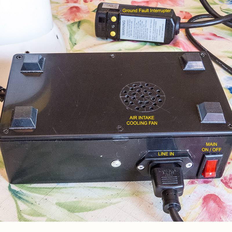
I got the wiring finished and used my ground fault circuit interrupter in doing the initial checks to see if everything works. Using a GFCI will reduce the chance of accidently putting a current of higher than about 5 mA across your heart. Only 75-100 mA can put your heart into fibrillation and thus cause death unless you happen to have a defibrillator handy or your wife knows CPR -- neither of which is the case for me. Everything works as expected, including the cooling fan. {big sigh of relief} But since assembly took longer than anticipated, I decided to do the trial roast runs tomorrow. So I thought I'd post a few pictures of it. Two optional elements are the fan speed control (~$5) and the scale (~$10). With the scale and dimmer the cost including the popper is around $73; under $60 without them. I'll post a parts list later in case anyone is interested in doing the mod.
ChicagoJohn attached the following images:


|
|
|
|
| ChicagoJohn |
Posted on 08/04/2015 8:20 AM
|
|
Pounder Posts: 513 Joined: June 15, 2015 |
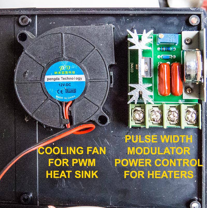
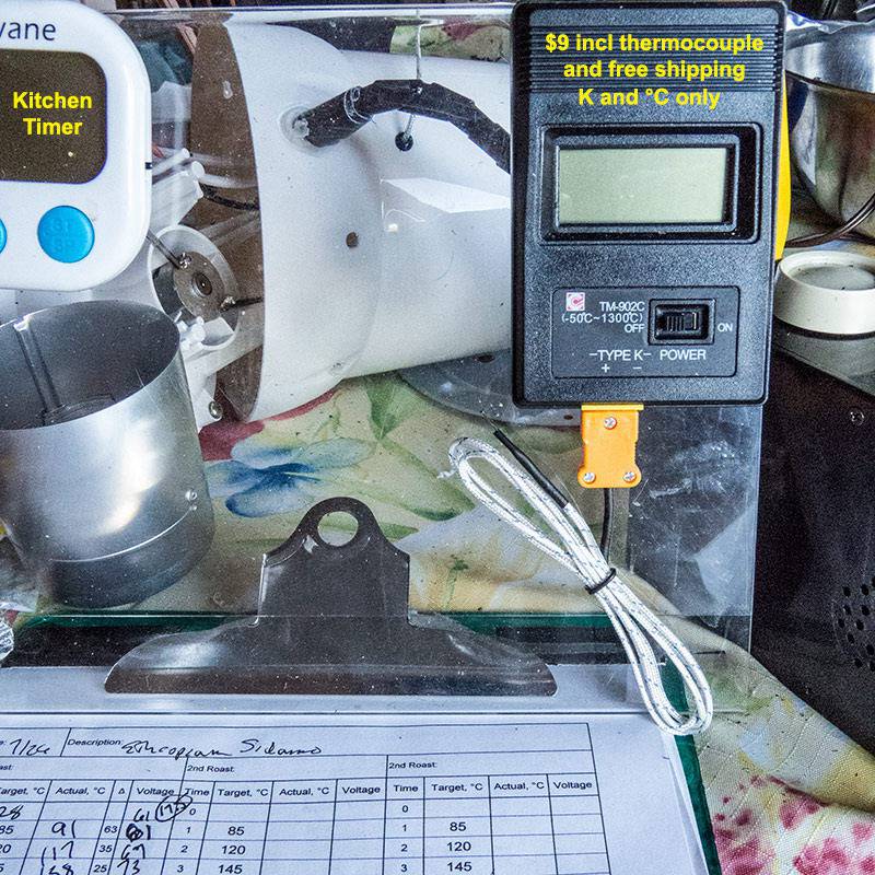
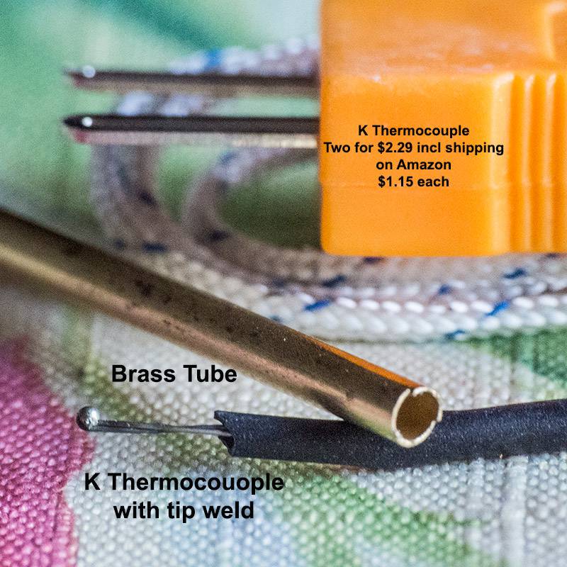
I've attached a few more images detailing how I did the wiring and how I install thermocouples. I used a piece of the box to hold the diode bridge and 7812 regulator, wired as shown. Not very pretty, but functional. I use the same silicone RTV to hold the 7812 in place and also to hold the fan and PWM on the base. For $8 I got a pyrometer type display device for K thermocouples with Centigrade output only (which happens to be what I use) and that came with a K thermocouple. I bought two more with 3 ft fiberglass leads for only $1.15 each with free shipping. The welded tips require some kind of protection for this application, so I used a small brass tube cut to about 1 inch length. I used the RTV to soak the tip and insert it into the tube, putting more into the end in the chamber to prevent anything from getting into it. I used aluminum tape on the outside to make a "stop" and I used more RTV inside and outside to form a gasket to hold it in place. Before doing this, I ran it through a rubber grommet in the side of the popper. I'm not interested in NIST traceability of calibration in this application, only in getting reasonable repeatability from roast to roast. Based upon my results so far, I think I'll be able to detect any significant drift in 1C onset temperatures, which so far have been quite consistent for a given variety.
ChicagoJohn attached the following images:


|
|
|
|
| ChicagoJohn |
Posted on 08/04/2015 10:31 AM
|
|
Pounder Posts: 513 Joined: June 15, 2015 |
So apart from any questions you might have, I will end the thread here with the parts list. Unless otherwise noted, parts obtained from Amason and prices include shipping (AmazonPrime) $17.52 Presto 04820 PopLite Hot Air Popper (optioinal) $8.75 American Weigh Scales Black Blade Digital Pocket Scale, BL-1KG-BLK 1000 by 0.1 G SELL $12.99 DROK? Digital Current Voltage Multimeter AC 100-300V 100A Voltage Amperage Meter, AC Volt Amp Testing Gauge Power Monitor LCD Dual Display Voltage $2.87 Interpower 8301213 IEC 60320 C14 Screw Mount Power Inlet with Quick Disconnects, IEC 60320 C14 Socket Type, Black, 10A/15A Rating, 250VAC Rating $7.45 Hammond 1591ESBK ABS Project Box Black $2.06 Black Brushless DC Cooling Blower Fan 2 Wires 5015S 12V 0.14A 50x15mm (optional) $3.90 Gardner Bender 73421 Spiral Wrap, 3/8-Inch in Diameter X 3 1/2-Feet Long, Black $6.25 AC 15A/250V 20A/125V ON-OFF 2 Position SPST Boat Rocker Switch 10pcs $4.63 PWM AC Motor Speed Control Controller 2000W Adjustable Voltage Regulator 50-220V $11.00 Packard 24VAC transformer ? Home Depot free shipping with pick up at store $4.50 Funnel Ace Hardware in Homeware section (optional) $5.00 SPST Dimmer for incandescent lighting ? Home Depot $5.90 5 pcs OF L7812CV LM7812 L7812 Voltage Regulator IC + 12V / Integrated Circuit ============= Other Optional and Spare Parts ============================================== $5.06 10Pcs 250V 10A 240C Celsius Circuit Cut Off Temperature Thermal Fuse $1.84 10 Pcs Molded Plastic Case 1000V 10A Rectifier Diodes 10A10 $2.29 2 Pcs K Type 800C Wire Lead Measuring Thermocouple Sensor 1M 3.3Ft $8.99 AODE? K-Type Digital Thermometer + TP-01 Thermocouple Probe Cable 110003 $9.97 Wrenwane Digital Kitchen Timer |
|
|
|
| ChicagoJohn |
Posted on 08/05/2015 1:30 PM
|
|
Pounder Posts: 513 Joined: June 15, 2015 |
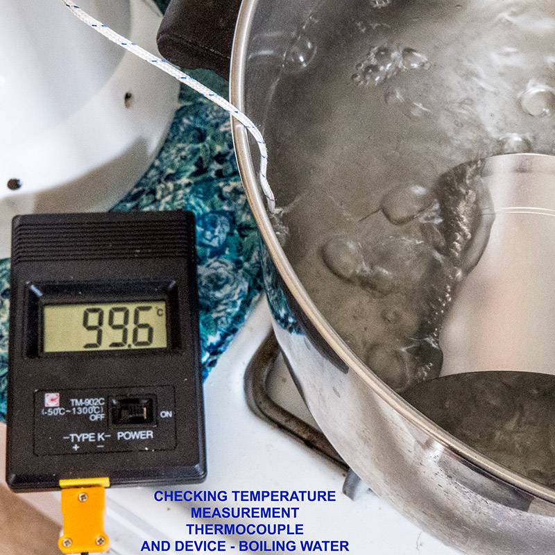
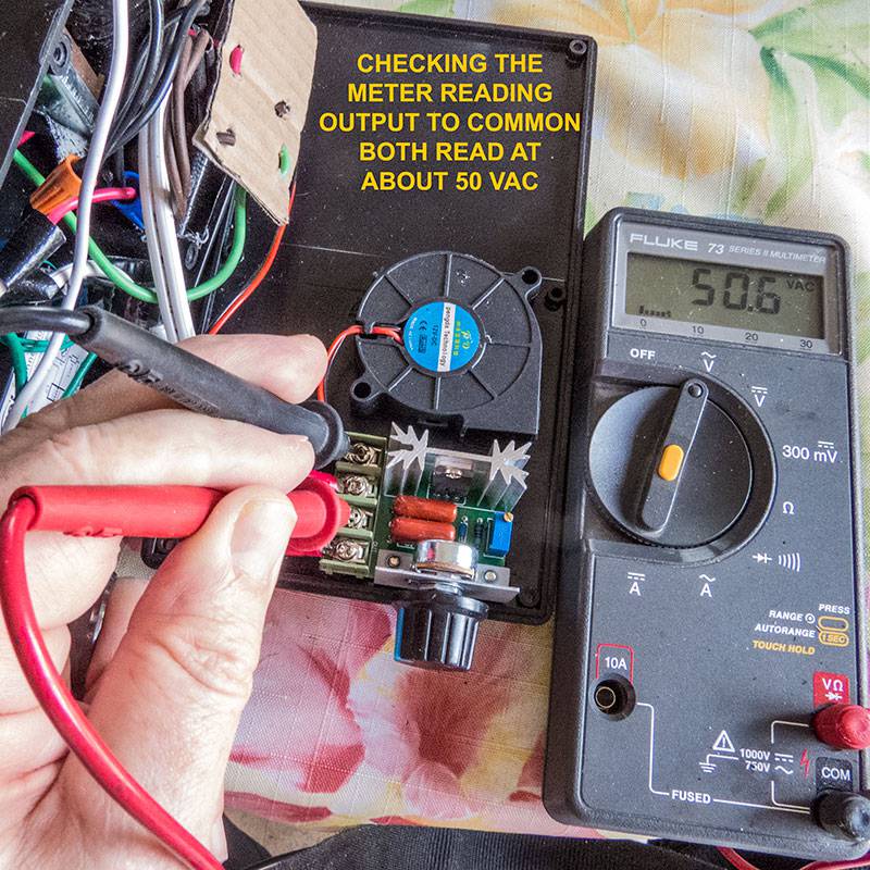
Well, to paraphrase Michael C. in Godfather Part III, Just when I thought I was out, circumstances pull me back in again... I was doing another roast today with the new unit and had a major problem in that there was a discrepancy between amperage and voltage and then the voltage and amperage locked to maximum and I had to turn the power to the coils on and off to reset it. This happened several times. I was hoping it would "go away" but it didn't. So I shut it down. This kind of thing happens sometimes, and when it happens, you just have to take a deep breath and figure out what is going on. In this case, the most likely differences between my previous build, which has been working flawlessly, are the following (a) thermocouple, (b) digital meter for voltage and amperage, and (c) PWM controller. These are all new elements. So first I decided to check out calibration of the thermocouple in-situ in ice water and boiling water, which should produce centigrade values of 0 and 100, respectively. As the images show, the readings are well within acceptable limits. This, of course, does not necessarily extrapolate to higher temperatures since the conversion of thermocouple emf to temperature takes a six or seven degree polynomial curve fit. But it is at least a basic check. Next I decided to check the meter versus my trusty Fluke VOM. This involved opening things up and checking it "live". Here is were it is very, very, very advisable to use a ground fault circuit interrupter, and I did. I learned that indeed the digital meter display I installed was reading quite close to my Fluke meter. Bad news was that the PWM was doing the same thing -- locking onto maximum power and refusing to respond to the potentiometer. And the maximum voltage reading was verified by my Fluke meter. So the digital meter was not the problem. Conclusion: Bad PWM for $4.65. Corrective Action: Order a new PWM for $17 from Amazon.com with free Prime shipping. I will have to see how I can fit it into the current build design when it arrives Friday or Saturday. With no small degree of chagrin, I then recalled the words of the famous John Arbuckle from a coffee commercial on TV when I was growing up who reportedly said, "You get what you pay for." This, ironically, was associate with a coffee commercial of a brand I've forgotten. Here's the scary part.... ================================ United States Patent Office John Arbuckle, JR., Allegheny City, Pennsylvania. Letters Patent No. 73,486, dated January 21, 1868 Improvement in Roasted Coffee. To all whom it may concern: Be it known that I, John Arbuckle, Jr., of the city and county of Allegheny, in the State of Pennsylvania, have invented a new and useful Improvement in "Roasted Coffee;" and I do hereby declare that the following is a full and exact description thereof. The nature of my invention consists in roasting coffee and then coating it with a glutinous or gelatinous matter, for the purpose of retaining the aroma of the coffee, and also act as a clarifying-agent when the ground coffee has been boiled in water. To enable others skilled in the art of "roasting coffee" to use my invention, I will proceed to describe its operation or preparation. ======================================
ChicagoJohn attached the following images:

|
|
|
|
| ChicagoJohn |
Posted on 08/06/2015 7:39 AM
|
|
Pounder Posts: 513 Joined: June 15, 2015 |
I worked with this PWM issue further today and the problem appears to be simply that it is undersized and overheats. It is rated at 2000 Watts, but it overheats at around 500-600 watts. When that happens, it begins acting erratically and then locks into maximum power and will not respond to the potentiometer. The PWM I used on my previous build, which has been working flawlessly from day 1, is the one shown below. It is rated at 4000 Watts, so if we apply the same factor, it is probably good to around 1000W where I'm using it. It is entirely possible that if the 2000W unit were operated under optimum cooling conditions for the heat sink, it would do better. I don't think it is defective, just rated too highly in wattage capability. But in this application, that would not be realistic, and I therefore think the unit below is preferable. I will be able to verify this tomorrow. Amazon Prime, free 2 day shipping. $16.66 SMAKN? AC 0-220V 20A Pulse Width Modulator PWM Electric Motor Speed Controller Max 4000W |
|
|
|
| JackH |
Posted on 08/06/2015 8:20 AM
|
|
Administrator Posts: 1809 Joined: May 10, 2011 |
That SMAKN looks like a much better unit. Heavier heat sink and possibly thermally attached to the case as well. I hope it works for your roaster. ---Jack
KKTO Roaster. |
|
|
|
| ChicagoJohn |
Posted on 08/06/2015 8:48 AM
|
|
Pounder Posts: 513 Joined: June 15, 2015 |
Quote JackH wrote: That SMAKN looks like a much better unit. Heavier heat sink and possibly thermally attached to the case as well. I hope it works for your roaster. Well, I posted a "Gen 2" mod in another thread, and that uses the SMAKN PWM, and I've done probably 25 roasts with absolutely no problems whatsoever. So I'm pretty sure it will work, and you are right on regarding the build quality. I guess I was hoping the 2000W rating for the much cheaper unit would be accurate, but I'm afraid it isn't. It would probably work for under 500W though. Thanks for your comment, and we'll know more tomorrow, I guess You can check out the Gen 2 thread on the Popcorn Popper Roasting forum if you want to and see what I've actually been using. In this thread I was trying to keep the cost as low as possible |
|
|
|

| Jump to Forum: |
Powered by PHP-Fusion Copyright © 2024 PHP-Fusion Inc
Released as free software without warranties under GNU Affero GPL v3
Designed with ♥ by NetriXHosted by skpacman