
Login

Shoutbox
You must login to post a message.
renatoa
07/26/2024 3:49 PM
Bill grubbe and Jk, 
allenb
07/26/2024 5:15 AM
Spiderkw Welcome to HRO!

renatoa
07/24/2024 8:31 AM
ramiroflores and John123,

 ?
?
?renatoa
07/21/2024 1:18 AM
 , Luislobo
renatoa
07/19/2024 11:28 AM
Koepea,
Forum Threads
Newest Threads
Skywalker roaster modsBackground Roast Iss...
Hello from Arkansas
TC4ESP
Green coffee reviews
Hottest Threads
| Skywalker roaster... | [375] |
| TC4ESP | [115] |
| War on Farmers by... | [47] |
| Adventures in flu... | [26] |
| Hello! (soon) Roa... | [17] |
In Memory Of Ginny

Donations
Latest Donations
dmccallum - 10.00
JackH - 25.00
snwcmpr - 10.00
Anonymous - 2.00
Anonymous - 5.00
dmccallum - 10.00
JackH - 25.00
snwcmpr - 10.00
Anonymous - 2.00
Anonymous - 5.00
Users Online
Guests Online: 4
Members Online: 0
Total Members: 8,393
Newest Member: Bill grubbe
Members Online: 0
Total Members: 8,393
Newest Member: Bill grubbe
View Thread
Who is here? 1 guest(s)
 P1 Group Build?
|
|
| walt_in_hawaii |
Posted on 09/15/2016 5:55 PM
|
|
1/4 Pounder  Posts: 133 Joined: August 24, 2016 |
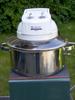
Tried a quick roast (beans are espresso mix1 from Happy Mug) with the TC in place: It was 150g of greens and I had to go darn near 130% on the fan control to get them moving. I took them about 20 seconds into 2C and boy do I have a lot to learn on this setup... its nothing like my P2 clone. The roasting chamber is larger, so I used a larger batch of beans (150g instead of 110g) but the beans at this weight are difficult to move, so although a visual inspection of the finished beans shows them pretty evenly done, I think I have to move down in batch size. Next I will try 125g. I also noticed as I cut airflow down, the temp really started moving higher... the effect is not that noticeable with the P2(also, I'm using a stick to stir on the P2), but on the P1 its very pronounced. Predictably, the roast time was also too long, about 18min where I'm used to a 2C in 12-13min. But I was not maxed on power yet, I could probably have upped the power a bit and got into the 12min mark, just wanted to keep something in reserve while I'm trying to learn this machine... The TC seems to be reading much different as well, its indicating much lower than I'm used to... 2C started around 410F? and on my P2 that usually happens near 445F. I'm not sure if I can calibrate this TC, I haven't read any of the thermometer documentation yet. So, all you guys with P1s out there, what is your normal batch size? Edited by walt_in_hawaii on 09/15/2016 6:08 PM |
|
|
|
| snwcmpr |
Posted on 09/15/2016 7:32 PM
|
 1 1/2 Pounder  Posts: 925 Joined: March 03, 2011 |
Quote 2C started around 410F? I say that is more accurate than 445. I get 2C anywhere from 385 to 405. When I used a P1 I poured until it almost stopped spinning. I mean like just barely moving. It would increase in speed as the beans dried out. --------------
Backwoods Roaster "I wish I could taste as well as I wish I could roast." As Abraham Lincoln said "Do not trust everything you read on the internet". |
|
|
|
| walt_in_hawaii |
Posted on 09/15/2016 7:35 PM
|
|
1/4 Pounder Posts: 133 Joined: August 24, 2016 |
3rd roast, this is actually 3 separate roasts done back to back. First in the batch is the middle, an Ethiopian Kochere which I took to an indicated 415F which is probably underdone, but I'm tryiing to get ahold of what this TC is telling me and I know its indicating lower than I'm used to. Next was the one on the right, here is a closer shot:  This is the famous Ka'u bean, note the huge size... these were hard to get into motion! they are so big and heavy. These were taken to an indicated 425F, maybe a minute outside of 1C. Lastly, was the one on the left, which is a Guatemalan Esperanza: this was taken to about 30 seconds into 2C, an indicated 440F? Its hard to tell, it is obvious that initial drying of the beans is much slower in the P1, by 4 minutes I always see light color change in the P2 clone. But in P1 I dont get yellowing until around 6 minutes so the delta T is very slow at first. But then it accelerates and delta T is very steep at the end. I was finishing these 3 roasts in about 14 minutes, better; but I was using around 95% power with little in reserve, which I don't like. Development time was round 3 minutes mostly, far as I could tell. |
|
|
|
| btreichel |
Posted on 09/15/2016 10:29 PM
|
 1/4 Pounder Posts: 187 Joined: May 07, 2007 |
280 grams, 10 to 12 minutes. But then the tilt and the 'belly' of the chamber helped. |
|
|
|
| walt_in_hawaii |
Posted on 09/18/2016 10:37 AM
|
|
1/4 Pounder Posts: 133 Joined: August 24, 2016 |
Hmmm, still no lantern glass from Menard's (so I can try a bigger roast sample size). However, I found a new problem after the 3 back to back roasts above: I cannot pull the plug out from the router speed control (now heat control)! One of the prongs appears to have welded itself into the socket... one side can move slightly, but the other side can't move at all. I know the unit gets hot, but didn't think it would WELD itself together! Has this happened to anyone else?? |
|
|
|
| btreichel |
Posted on 09/18/2016 10:50 AM
|
|
1/4 Pounder Posts: 187 Joined: May 07, 2007 |
Nope, but I did have to re-wire / repair the variacs more than once. |
|
|
|
| walt_in_hawaii |
Posted on 09/19/2016 3:33 AM
|
|
1/4 Pounder Posts: 133 Joined: August 24, 2016 |
I'm back from a trip to California this weekend; did about 4 roasts back to back on the P1 today because I met a super nice guy on the plane, turns out he grew up about a block away from me in Pauoa Valley in Honolulu! small world. I promised I'd send him some fresh roasted coffee. On the 4th roast, after reaching about 330F the heat clicked off! Awwww man, the thermostat?!! I did some errands, came back and tried again; and it clicked off AGAIN at 330F so this is permanently reset for some reason... took apart the P1 today and destroyed the ceramic contact points in the thermostat, put it back together... lost the daylight and had no time to do another roast. A quick test confirmed that it seems to be working OK again, but I won't be able to tell until I do another roast. I finished off the short roast from earlier today on my old P2, it was an Ethiopian Agaro and I did a quick very small quantity of pour through with it; WOW, this is a very tasty bean! Dropped it around 427F. Tonight, I was a bit restless from my trip and decided to just pile into the next phase of modifications and took apart the jaws on my lathe's chuck to invert them so they can hold the huge piece of solid aluminum... will post pics in a little bit. |
|
|
|
| walt_in_hawaii |
Posted on 09/19/2016 4:00 AM
|
|
1/4 Pounder Posts: 133 Joined: August 24, 2016 |
Here is the chuck in its normal orientation, and the chunk of aluminum I will be working on. Its deceptively small looking in this shot, but trust me its large and very heavy: Jaws of the chuck have been inverted and the round stock put into it:  I put a micrometer on it to measure the radial runout and turned it around by hand, it came to about 5 thousandths of an inch, which actually is very good, so left it there. First order of business is the skim off a thin layer from the front face of the round stock. This is called 'truing' the face so it will register dead flat in relation to the radial axis:  If you look very closely you can see I didn't cut quite deep enough, there are a few small scratches still on the face from the saw cut. But its good enough for me. Next order of business is to do the same thing to the side, take off a thin layer to true it up.. I ended up shaving off around 7 thousandths of an inch:  Note that the back where the jaws are gripping the thing can't be cut right now, I'll have to take it out and turn it around end for end and finish truing the sides later. I don't have the whole design in my head yet, I'm sort of designing it as I go and seeing what materializes in front of me... so the next step would be to drill the center the same diameter as the roast chamber, which is around 2.825":  The center is first drilled with a short stubby drill called a 'centerdrill' to ensure the hole is centered; then you follow it with a regular drill bit. What I can't show is the rotation of this much aluminum with so much mass, has to be kept very low as a piece turning this fast will overheat the cutting bits quickly, so everything takes much longer working at such low speeds. |
|
|
|
| btreichel |
Posted on 09/19/2016 10:15 AM
|
|
1/4 Pounder Posts: 187 Joined: May 07, 2007 |
Walt, either you have too many toys, or I have to few |
|
|
|
| walt_in_hawaii |
Posted on 09/20/2016 11:26 AM
|
|
1/4 Pounder Posts: 133 Joined: August 24, 2016 |
Guilty as charged, sir! Although I humbly suggest the latter may be true as well... |
|
|
|
| walt_in_hawaii |
Posted on 09/21/2016 3:25 AM
|
|
1/4 Pounder Posts: 133 Joined: August 24, 2016 |
The 1/2" drill bit is changed out to 1" and drilled: Drill bits pretty much max out at 1". There are larger ones, but generally that's about as big as they go; but my hole has to be 2.825" so the hole has to be bored out bigger... first with a small boring tool:  Then with a much thicker, stronger boring bar:  Here the hole is approaching final dimensions:  Finished boring to final diameter of exactly 2.825"  Using a parting tool to cut the piece in half so that I have 2 shorter pieces. One for each of my P1s (why build one when you can build 2 for nearly the same price? the real cost is in the man hours of labor needed to build them; but once you figure out how to make the parts and build it, the 2nd one takes nearly no extra time!)  That's it for tonight, I'm bushed. |
|
|
|
| JackH |
Posted on 09/21/2016 5:49 AM
|
 Administrator Posts: 1809 Joined: May 10, 2011 |
I am a bit confused. What part is being created here?
---Jack
KKTO Roaster. |
|
|
|
| walt_in_hawaii |
Posted on 09/21/2016 11:24 AM
|
|
1/4 Pounder Posts: 133 Joined: August 24, 2016 |
Jack, excellent question! but if all goes well, then this will be an adapter ring, the top of the ring will fit the 3-1/2" bake-a-round pyrex tube; the bottom of the ring will mate up to the P1's roast chamber. It's not that obvious, but as I get closer to finishing, it should be easier to see it. |
|
|
|
| JackH |
Posted on 09/21/2016 3:59 PM
|
|
Administrator Posts: 1809 Joined: May 10, 2011 |
I see. Excellent work Walt!
---Jack
KKTO Roaster. |
|
|
|
| walt_in_hawaii |
Posted on 09/22/2016 3:50 AM
|
|
1/4 Pounder Posts: 133 Joined: August 24, 2016 |
My hurricane glass from Menard's arrived today! Unfortunately, none of the 3 lamps fit my roaster :( So, I continued the cut I started last night:  Cleaned up the piece that was still mounted on the lathe:  Then cut a relief depression to fit the Bake A Round, I chose to make it 1/2" deep. The bake a round measures 3.710" to 3.720" diameter (its not exactly round), and I threw in an extra .050" for padding (have to put in some sort of gasket or soft seal) so that makes the hole 3.770" diameter and 1/2" deep:  trial fit:  Now I have to wait for the hose clamps I ordered, they should be here any day now. |
|
|
|
| btreichel |
Posted on 09/22/2016 8:12 AM
|
|
1/4 Pounder Posts: 187 Joined: May 07, 2007 |
My p1 has a outer lip and base / shelf that it might fit into. Normally, the glass is just a tad big. A use a small bead of silicone rtv to seal the two. Food safe and good to 500f. Basically like the adapter you are building. |
|
|
|
| walt_in_hawaii |
Posted on 09/22/2016 3:19 PM
|
|
1/4 Pounder Posts: 133 Joined: August 24, 2016 |
Hmmmmmmmmm. Now you've got me thinking. I hate to see the glass from Menard's go to waste, and it would be a VERY simple operation to machine a simple, very short aluminum 'sleeve' that would go over the outside lip of the lantern glass, then slide over the top of the roast chamber/fan... you could rtv/silicone it to the glass, which is cooler, then just use a friction fit to the roaster/base and it wouldn't be this huge contraption I have here which only Frankenstein (and me) could love... I'll go and see if the bay has any aluminum pipe that is close in size. It would be a very simple project, and then these 3 glass globes would not go to waste. |
|
|
|
| walt_in_hawaii |
Posted on 09/22/2016 3:21 PM
|
|
1/4 Pounder Posts: 133 Joined: August 24, 2016 |
Ha! in fact, I think I might get by with just a simple piece of turbo silicon hose coupling, it slides over a 3" pipe just fine and should accommodate the popper and the glass perfectly... these are used by speed shops for intercooler piping and very common. I'll call a couple shops down here and see if I can scrounge a small piece for a trial fitting.... |
|
|
|
| walt_in_hawaii |
Posted on 09/23/2016 3:03 AM
|
|
1/4 Pounder Posts: 133 Joined: August 24, 2016 |
OK, so the top of the adapter ring is pretty much done; tonight I finished up the bottom by removing most of the metal and leaving a small ring next to the internal diameter: Trial fitting... it fits perfectly into the top of the roast chamber, BUT... I didn't read the dials correctly, and the 'lip' is too shallow, by exactly .100" ...  Bottom fits fine, I'll have to figure out a way to bolt it to the original bosses.  But for now I have to put this back into the lathe and cut a bit deeper to make the lip extend out another .100"  |
|
|
|
| BenKeith |
Posted on 09/23/2016 7:41 AM
|
|
Pounder  Posts: 485 Joined: April 21, 2014 |
You will probably need to put a taper on the inside of your adapter to keep beans from just sitting on the lip. |
|
|
|
| walt_in_hawaii |
Posted on 09/23/2016 12:00 PM
|
|
1/4 Pounder Posts: 133 Joined: August 24, 2016 |
Hi Benkeith. Yes, there will be a taper on the inside, to go from the roast chamber dimension to the inside of the bake a round chamber dimension, and it should be a very shallow taper to allow the beans to move freely from one to the other. I'm still juggling that part in my head, because once you cut the taper you can no longer hold the workpiece by the insides (you can only tension a straight cylinder), and I think I might have to hold it from the insides to cut the outside to make the mounting boss... trying to figure out a way around that, not sure yet. |
|
|
|
| BenKeith |
Posted on 09/23/2016 12:41 PM
|
|
Pounder Posts: 485 Joined: April 21, 2014 |
I would just throw in in my three jaw chuck and make shallow cuts to keep from loading the piece and having walk or slip in the jaws. That few thousandths out will never be noticed. You might have a little line in three places where the jaws were but if you don't over tighten it, they probably won't be noticeable. |
|
|
|
| walt_in_hawaii |
Posted on 09/24/2016 11:59 PM
|
|
1/4 Pounder Posts: 133 Joined: August 24, 2016 |
OK, I've fixed the 'short' lip... both adapters are the same (one for a backup P1): Now I have to cut a taper to 'blend' the diameter from the roast chamber up to the bake a round. I picked 29 degrees because the lathe is already set up at 29 degrees for cutting SAE threads:  It is obvious the 29 degree is too shallow, the taper does not reach down far enough:  So, next I try 50 degrees and take another cut:  It is obvious that this cut is too steep; I need something about in the middle of those 2 angles, so I pick 42.5 degrees and take another cut:  Just right. Now I have to mount it to the P1. The calipers show the exact spacing between the mounting holes (3.750" center to center):  and, as you can see, this bolt spacing is right in the middle of the transition area in the spacer, so I can't do separate mounting point under the flange, which is what I was originally planning. I decide to just cut straight into the top. Here is the adapter mounted into a dividing head, which can spin the unit clockwise or counter clockwise an exact number of degrees, so I can rotate it 180 degrees and drill another hole exactly opposite the first:  After 2 holes are drilled, I bolt up one side; the other side is OFF slightly, by about half a hole's diameter:  I'm not sure where the inaccuracy is coming from, the original mounting boss may not be exactly 180 degrees from the other? So I end up cutting one of the holes slightly sideways to let the mounting bolt move sideways slightly:  P1 now has the adapter plate mounted securely. Now I put the pyrex tube into the adapter; I have to find some insulating material to soften the contact between the plate and the glass so it doesn't crack. Also, the hose clamps I ordered are the WRONG size:  |
|
|
|
| BenKeith |
Posted on 09/25/2016 6:57 AM
|
|
Pounder Posts: 485 Joined: April 21, 2014 |
Wow, you had to machine a new piece. That was expensive. If your design requires being able to lift the glass off, I would look at cutting a couple O-ring groves and fit O-rings in it to give it a slight friction fit. If it's a permanent fit, they sell food grade, high temp silicone, but most you find is red. I just noticed your mounting holes, that's going to make cutting O-ring groves a pain. Not sure the purpose of the clamp Edited by BenKeith on 09/25/2016 7:07 AM |
|
|
|
| walt_in_hawaii |
Posted on 09/25/2016 12:18 PM
|
|
1/4 Pounder Posts: 133 Joined: August 24, 2016 |
Benkeith, the clamp is going to be used like on the original post indicated. I want to be able to take the glass off for washing, so siliconing it in place is not an option (although would be the easiest thing to do by far). The clamp will have to be modified slightly, I'll have to weld little ears or tabs onto it so I can drill/tap the mount to attach it to the plate. O rings are a great idea! ....too bad I can't do that, I've machined O ring grooves for other projects, and the fit has to be fairly close. In this project I allowed for a rather large space between the glass and the plate, and no O ring exists that can fill that gap, I would have had to plan on it from the start and made only a small gap... but great idea, wish I had thought of it! |
|
|
|

| Jump to Forum: |
Powered by PHP-Fusion Copyright © 2024 PHP-Fusion Inc
Released as free software without warranties under GNU Affero GPL v3
Designed with ♥ by NetriXHosted by skpacman