
Login

Shoutbox
You must login to post a message.
renatoa
07/26/2024 3:49 PM
Bill grubbe and Jk, 
allenb
07/26/2024 5:15 AM
Spiderkw Welcome to HRO!

renatoa
07/24/2024 8:31 AM
ramiroflores and John123,

 ?
?
?renatoa
07/21/2024 1:18 AM
 , Luislobo
renatoa
07/19/2024 11:28 AM
Koepea,
Forum Threads
Newest Threads
Skywalker roaster modsBackground Roast Iss...
Hello from Arkansas
TC4ESP
Green coffee reviews
Hottest Threads
| Skywalker roaster... | [375] |
| TC4ESP | [115] |
| War on Farmers by... | [47] |
| Adventures in flu... | [26] |
| Hello! (soon) Roa... | [17] |
In Memory Of Ginny

Donations
Latest Donations
dmccallum - 10.00
JackH - 25.00
snwcmpr - 10.00
Anonymous - 2.00
Anonymous - 5.00
dmccallum - 10.00
JackH - 25.00
snwcmpr - 10.00
Anonymous - 2.00
Anonymous - 5.00
Users Online
Guests Online: 6
Members Online: 0
Total Members: 8,393
Newest Member: Bill grubbe
Members Online: 0
Total Members: 8,393
Newest Member: Bill grubbe
View Thread
Who is here? 1 guest(s)
 First roasting
|
|
| pandiani |
Posted on 11/13/2016 11:14 AM
|
|
1/4 Pounder  Posts: 74 Joined: November 05, 2016 |
I would like to continue, possibly, with the popcorn popper, because for two people, the amount of beans to be toasted is perfect. While the bread machine, besides being much larger. I make a proposal, if you want, and no one is forced, I dismount my popper, I take pictures, and step by step you tell me what to do. Then send you pictures, I approved the project (always step by step) and go forward. It could be the first work in the world forum. I 'd like with your help, but I would not be a problem to someone |
|
|
|
| pandiani |
Posted on 11/13/2016 11:56 AM
|
|
1/4 Pounder Posts: 74 Joined: November 05, 2016 |
So correct me if I'm wrong: I will have a transformer, a dimmer and a switch. From a hot wire of the current, part of a wire that goes to the trasformer, then depart three wires, one will go to the switch and one to the dimmer, the third wire will go to the popper heating coil. The other pole of the switch, will go to the second cable popper resistance, thus closing the first circuit. The other dimmer wire connects to the primary splitter transformer. Then depart from the transformer; two wires that go to the popper fan. So far everything should be ok. |
|
|
|
| pandiani |
Posted on 11/14/2016 12:44 PM
|
|
1/4 Pounder Posts: 74 Joined: November 05, 2016 |
I wanted to take this modify, what do you say? http://www.instructables.com/id/Popcorn-machine-made-into-a-high-class-coffee-roa/ Utilizzerei l'adattatore del laptop per alimentare il motore del ventilatore and instead of the pulse width to control the fan speed, I would use this http://it.rs-online.com/web/p/dimmer/8356938/ what do you think |
|
|
|
| btreichel |
Posted on 11/14/2016 7:37 PM
|
 1/4 Pounder Posts: 187 Joined: May 07, 2007 |
Looked like it was in Italian However, 600w doesn't need translation. Fans are a lot less power. So it should be fine However, 600w doesn't need translation. Fans are a lot less power. So it should be fine |
|
|
|
| pandiani |
Posted on 11/15/2016 5:28 AM
|
|
1/4 Pounder Posts: 74 Joined: November 05, 2016 |
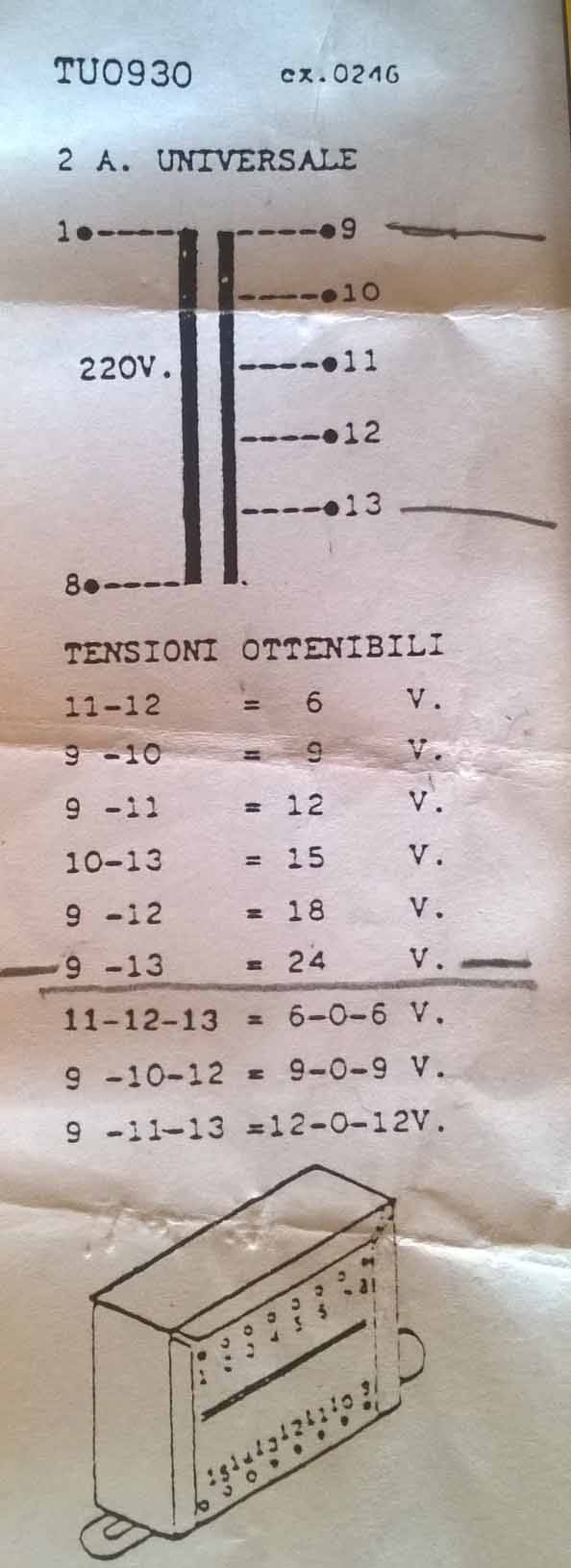
Quote btreichel wrote: Looked like it was in Italian However, 600w doesn't need translation. Fans are a lot less power. So it should be fineSorry D A question, the main resistance and the secondary must be connected together? I read on some threed to modify, that the secondary is better to take it off. ? My temperature does not go over 217 ? C, if I do not connect the secondary resistance, my temperature will be even lower? Also I found a transformer between the old things. It should go well?
pandiani attached the following image:
|
|
|
|
| ChicagoJohn |
Posted on 11/15/2016 7:22 AM
|
 Pounder  Posts: 513 Joined: June 15, 2015 |
Quote pandiani wrote: Quote btreichel wrote: Looked like it was in Italian However, 600w doesn't need translation. Fans are a lot less power. So it should be fineSorry D A question, the main resistance and the secondary must be connected together? I read on some threed to modify, that the secondary is better to take it off. ? My temperature does not go over 217 ? C, if I do not connect the secondary resistance, my temperature will be even lower? Also I found a transformer between the old things. It should go well? On the popper I modified, there were two coils in the heater area; the main heating coil and a smaller coil. The function of the smaller coil in the popper I modified is to act as a voltage divider and drop the AC voltage from 120VAC to about 24VAC at the point it attaches to the rectifier diodes for the DC blower motor. The four rectifier diodes form a "full wave bridge rectifier" which changes the 60 cycle AC sine wave to pulsed DC -- the rectifier diodes only allow the current to flow in one direction. You can find lots of information about this on the internet IF your motor also is DC instead of AC. What I decided to do was to simply connect the "secondary" smaller coil in parallel with the main heating coil. In my popper, this resulted in a resistance of about 9.5 ohms for the two coils in parallel. So at 120VAC RMS dropped across these two coils. by Ohm's Law Delta V = I X R (current in amps X resistance in ohms), the current would be 120 / 9.5 or 12.6 amperes. Power in watts is roughly equal to Volts X Amps, so in this case, at full power the wattage would be about 1,500 watts. If you were to disconnect the secondary coil, the coil resistance will be higher so the power dissipation in heat will be lower. So to get the maximum possible heating power, you may want to connect the two in parellel like I did. To control the heat, I decided to use a pulse-width modulator. What this does is to send the full line voltage to the heating coils but only for part of the time. This is called the "duty cycle". So if it sends full line voltage for 100% of the time, for my popper this will heat at 1500 watts. If it's 50% of the time, it will be 750 watts. This is set by turning a knob on the model I used. I connected a digital volt meter to it to enable me to reproduce settings accurately. If you're interested, you can find the posts describing what I did on a several threads on the popcorn popper section of the forum. To replace the power to the blower motor, I used a 50VA 24VAC transformer. While I used a single pole dimmer switch on the primary of the transformer to control the output and thus control the motor speed, I now realize that is not necessary and if I were to do it again, I would just run the motor at full speed and not use the dimmer switch. On my popper, the motor draws about 2.5 amps at 24 VAC so this is why I used a 50VA transformer. With a lower VA rating I tried, the transformer quickly overheated. The transformer case temperature should not exceed 170F (80C). Your system operates at 240 V I think you said. So all of the values will be different but similar principles should apply -- you will have to research that yourself. Whatever you do, make sure you buy and always use a good quality ground fault interrupter on the power line that goes to your modified popper. What these do is to monitor the amperage leakage and shut off the power if it exceeds about 4 mA. It only takes around 100 mA across the heart to put the heart into fibrillation, and unless one has a defibrillator handy and someone who is trained to use it, if one's heart would go into fibrillation, they would likely die. Roasting your own coffee maybe a worthwhile goal, but it's not worth risking your life. You may think I'm being overly dramatic, but this is very serious business at 120VAC and even more so at 240VAC. Mistakes do happen. They are always a big surprise until you later figure out what went wrong -- assuming you are still there to do that. The bottom line is that you should NOT simply try to follow a step-by-step recipe someone else gives you in such a project. If you try to do that, you will be assuming very high risk. What you should do to reduce risk is to thoroughly research and understand every aspect of the technology you are involved with before you start and determine a plan that will be best and safest for the particular situation you are dealing with in terms of equipment, power levels, etc. After you have done that and are certain you know what you are doing and not doing and why, then proceed very slowly and methodically, triple checking everything before you apply power for testing. Edited by ChicagoJohn on 11/15/2016 8:38 AM So many beans; so little time.... |
|
|
|
| pandiani |
Posted on 11/15/2016 8:48 AM
|
|
1/4 Pounder Posts: 74 Joined: November 05, 2016 |
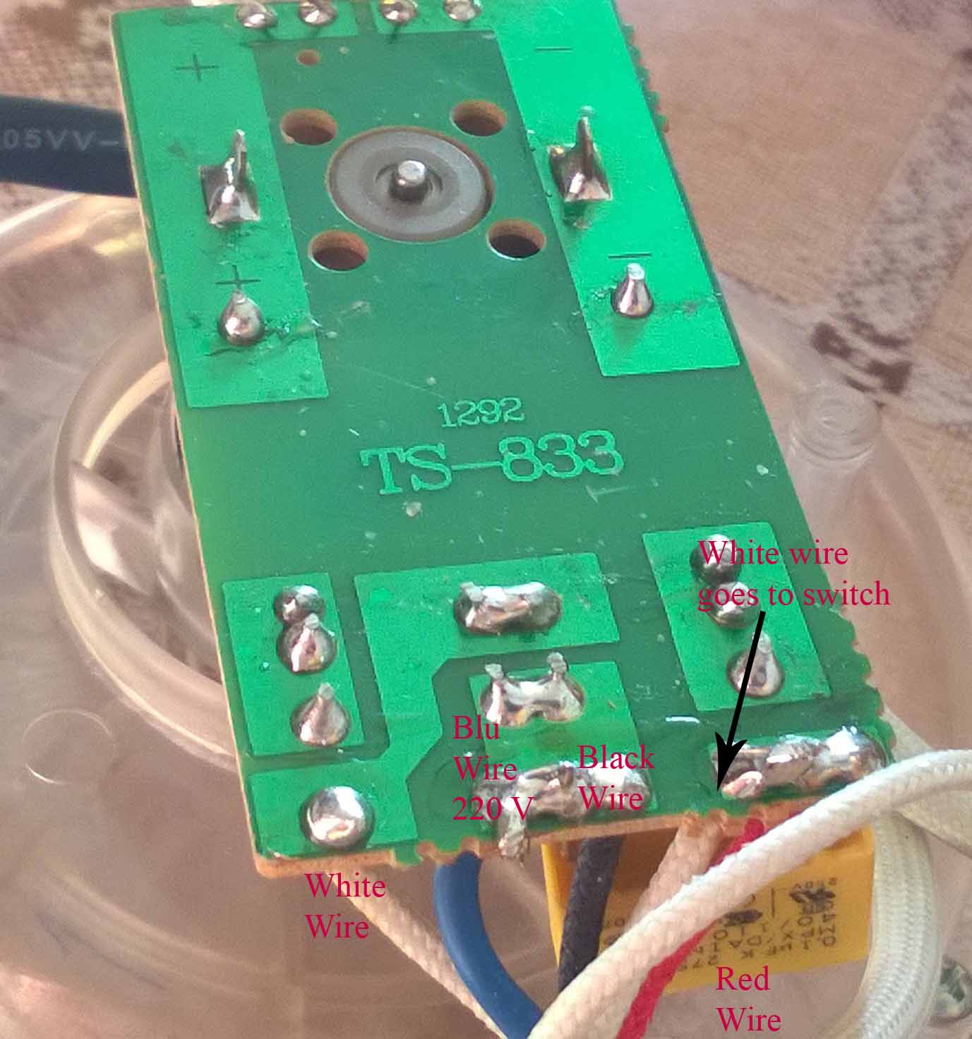
Thanks John, It is for what you said, I have prepared this post and these images. I am attaching photos, in one there are the letters, there is a diagram of my resistances and in a printed circuit board. This is to better understand the next steps. (As you can guess, I want to be 100% sure that what I'm doing is correct) - The black wire, running from A, goes to the printed circuit on the ventilator, and makes a bridge with a BLUE wire, which goes direct to 220 V. - The Red and Black wires go to the card and power the fan. Can I remove the card and keep the engine free as the first step? And then, the black wire feeds the small resistance, which should be connected in series to the point D. At this point the red wire and the white wire can cut them. Correct me if I'm wrong
pandiani attached the following images:


|
|
|
|
| ChicagoJohn |
Posted on 11/15/2016 1:12 PM
|
|
Pounder Posts: 513 Joined: June 15, 2015 |
As I said in my previous reply, you will have to understand the circuit you are working with. If you are able to get some expert advice from someone knowledgeable in electronics where you live, I would strongly suggest that you do that. You can show them the popper you are working with and they can help you understand the circuits and how to change them. Perhaps someone else on the forum will have specific knowledge of the same make and model of popcorn popper you are working with. I do not and I cannot be certain enough about all of the important factors to advise you based upon the photos and drawings I've seen. There are a number of resources on the internet including YouTube videos and also some posts in the Popcorn Popper forum here on Homeroasters.org that describe modifications that have been done that are similar to what you want to do, but not using the same 220V system. My suggestion is that you spend some time looking examining these resources and then find someone local who can help you in applying that information to the specific project you are working on. As I said previously, it is important that you fully understand what you are doing before you proceed because the project you want to pursue has significant risks associated with it. So many beans; so little time.... |
|
|
|
| pandiani |
Posted on 11/15/2016 1:44 PM
|
|
1/4 Pounder Posts: 74 Joined: November 05, 2016 |
Quote ChicagoJohn wrote: What I decided to do was to simply connect the "secondary" smaller coil in parallel with the main heating coil. In my popper, this resulted in a resistance of about 9.5 ohms for the two coils in parallel. So at 120VAC RMS dropped across these two coils. by Ohm's Law Delta V = I X R (current in amps X resistance in ohms), the current would be 120 / 9.5 or 12.6 amperes. Quote ChicagoJohn wrote: Power in watts is roughly equal to Volts X Amps, so in this case, at full power the wattage would be about 1,500 watts. If you were to disconnect the secondary coil, the coil resistance will be higher so the power dissipation in heat will be lower. So to get the maximum possible heating power, you may want to connect the two in parellel like I did. My popper is 1200 watts, so for me it is necessary to connect them in parallel otherwise, not enough would warm Quote ChicagoJohn wrote: To control the heat, I decided to use a pulse-width modulator. What this does is to send the full line voltage to the heating coils but only for part of the time. This is called the "duty cycle". So if it sends full line voltage for 100% of the time, for my popper this will heat at 1500 watts. If it's 50% of the time, it will be 750 watts. This is set by turning a knob on the model I used. I connected a digital volt meter to it to enable me to reproduce settings accurately. a phase on the hot wire 220V., and the other on the wire coming from the switch? And with the pulse width you have eliminated the "TruePower Stepless Electronic Fan Speed Controller, Variable AC Motor rheostat" this: https://www.amazon.com/gp/product/B009KAEP7A/ref=ox_sc_act_title_1?ie=UTF8&psc=1&smid=A24XKISZSTLJ1P If it were possible, it would be great, because I can not find the fan speed controller. Pulse width, with what characteristics? Quote ChicagoJohn wrote: If you're interested, you can find the posts describing what I did on a several threads on the popcorn popper section of the forum. Quote ChicagoJohn wrote: To replace the power to the blower motor, I used a 50VA 24VAC transformer. While I used a single pole dimmer switch on the primary of the transformer to control the output and thus control the motor speed, I now realize that is not necessary and if I were to do it again, I would just run the motor at full speed and not use the dimmer switch. On my popper, the motor draws about 2.5 amps at 24 VAC so this is why I used a 50VA transformer. With a lower VA rating I tried, the transformer quickly overheated. The transformer case temperature should not exceed 170F (80C). I think might be fine Quote ChicagoJohn wrote: Your system operates at 240 V I think you said. So all of the values will be different but similar principles should apply -- you will have to research that yourself. Quote ChicagoJohn wrote:Whatever you do, make sure you buy and always use a good quality ground fault interrupter on the power line that goes to your modified popper. What these do is to monitor the amperage leakage and shut off the power if it exceeds about 4 mA. It only takes around 100 mA across the heart to put the heart into fibrillation, and unless one has a defibrillator handy and someone who is trained to use it, if one's heart would go into fibrillation, they would likely die. Roasting your own coffee maybe a worthwhile goal, but it's not worth risking your life. You may think I'm being overly dramatic, but this is very serious business at 120VAC and even more so at 240VAC. Mistakes do happen. They are always a big surprise until you later figure out what went wrong -- assuming you are still there to do that. Quote ChicagoJohn wrote:The bottom line is that you should NOT simply try to follow a step-by-step recipe someone else gives you in such a project. If you try to do that, you will be assuming very high risk. What you should do to reduce risk is to thoroughly research and understand every aspect of the technology you are involved with before you start and determine a plan that will be best and safest for the particular situation you are dealing with in terms of equipment, power levels, etc. After you have done that and are certain you know what you are doing and not doing and why, then proceed very slowly and methodically, triple checking everything before you apply power for testing. Unfortunately, the language does not help me, and that makes me spend more time. |
|
|
|
| BenKeith |
Posted on 11/15/2016 4:34 PM
|
|
Pounder Posts: 485 Joined: April 21, 2014 |
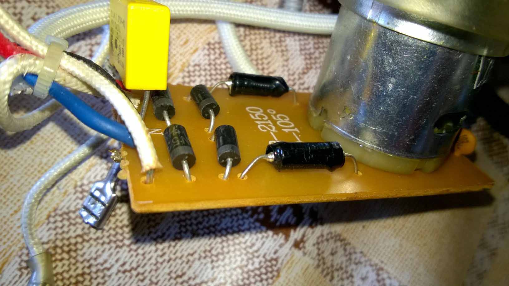
It would help if we had a picture of the other side (component) side of the board on the motor. It there are semiconductors, diodes, transistors etc the number off those. Then we can tell what you have controlling the motor. As John said, the heating coils are being used as a voltage divider and the white wire is the motor control voltage. I'm figuring they are taping off the coils to drop the voltage and then rectifying it do DC to run the motor. typically DC motors have much more torque that AC motors so they can make a much smaller, cheaper DC motor than if they used an AC motor. However, they could also be running it through a Triac and still leaving it an AC motor. I'm not real sure how familiar you are with this stuff so I'm a little Leary about asking you to do some voltage readings. Poking around inside something with 220VAC live inside of it, could make you dead outside of it, but knowing what the fan motor is running on would help. I looked on line to see if there was a schematic for it but barely found mention of the one you have. Also, looking at your diagram, the heating coils are not in parallel, they are in series. Are both coils 9.5 ohms each? If so, that would mean the white wire has 110VAC on it with 220VAC on the red and black wires. |
|
|
|
| pandiani |
Posted on 11/16/2016 6:41 AM
|
|
1/4 Pounder Posts: 74 Joined: November 05, 2016 |
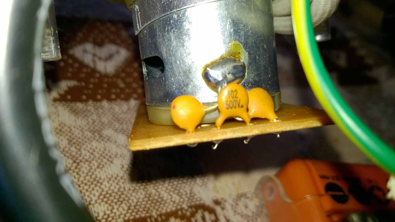
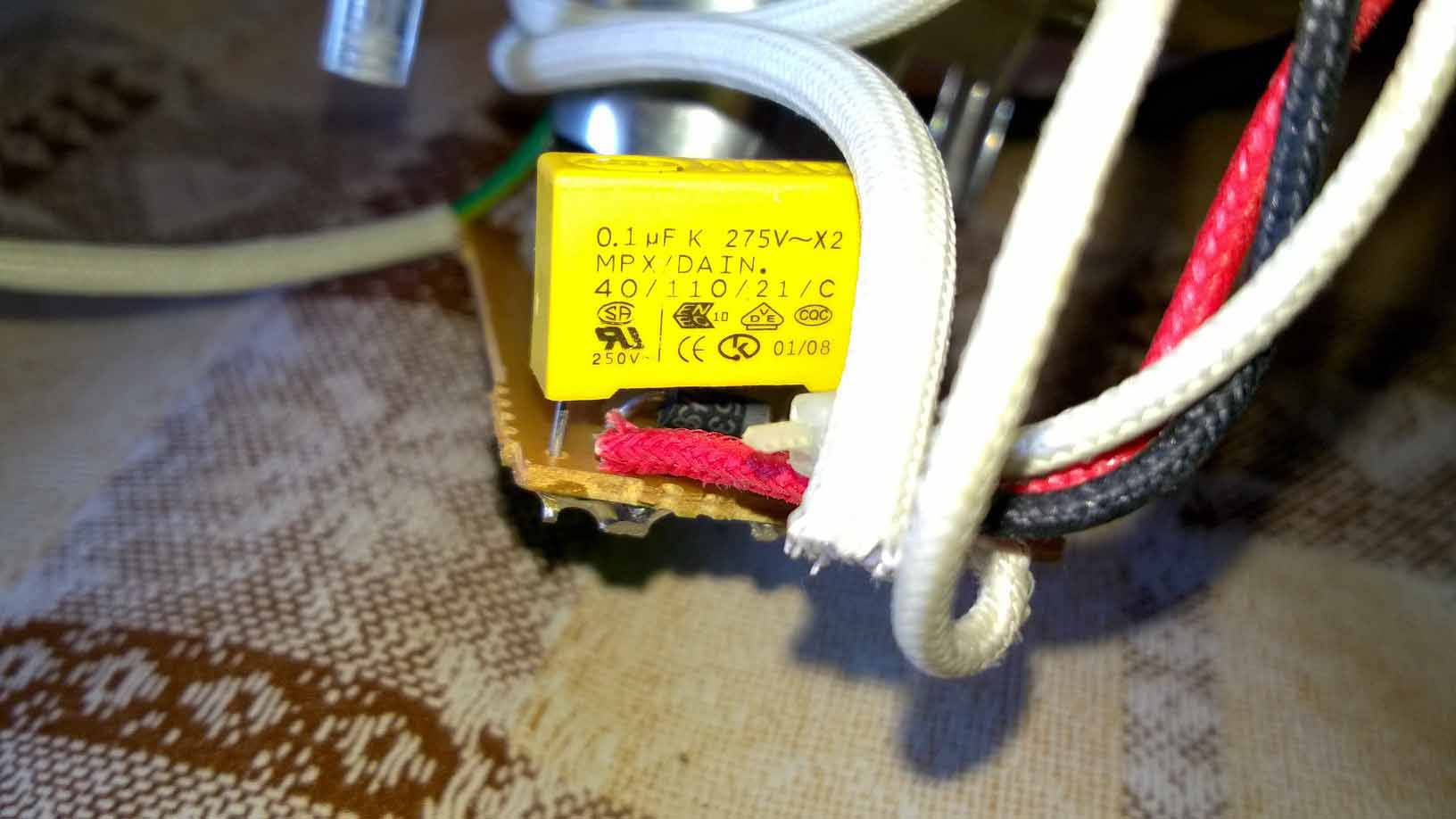
Quote BenKeith wrote: It would help if we had a picture of the other side (component) side of the board on the motor. It there are semiconductors, diodes, transistors etc the number off those. Quote BenKeith wrote:I'm not real sure how familiar you are with this stuff so I'm a little Leary about asking you to do some voltage readings. Poking around inside something with 220VAC live inside of it, could make you dead outside of it, but knowing what the fan motor is running on would help. I looked on line to see if there was a schematic for it but barely found mention of the one you have. but here we go about Arduino, and for me, it would be enough, check the fan and coil Quote BenKeith wrote: Also, looking at your diagram, the heating coils are not in parallel, they are in series. Are both coils 9.5 ohms each? If so, that would mean the white wire has 110VAC on it with 220VAC on the red and black wires. The two coils measured with the tester, at the extremes, measuring 41.5 OHM. see photos
pandiani attached the following images:


|
|
|
|
| BenKeith |
Posted on 11/16/2016 3:22 PM
|
|
Pounder Posts: 485 Joined: April 21, 2014 |
OK, it looks like basic bridge rectifier and you have about a 50V DC motor 41.5 ohms and 220VAC is going to give you about 1180 watts of heat. If one winding is 9.5 ohms that's going to give you approx. 50VAC going to the rectifier. Without doing all the fancy math for peak, load and other stuff, that's about what the rec is going to give you since I don't see any filter capacitors. So, to separate out the motor for variable speed control, you could probably take the white wire off and put a dimmer between the white wire and the board. It would not take a very large one since it's only dealing with the few watts the motor is pulling (50VAC and a couple amps max) and not the whole heater current. Since I haven't actually done this, I can't assure you it will work but don't see why it wouldn't. I would just stick me a triac in there, but that's about all a dimmer is and I'm a little more advanced than you. |
|
|
|
| BenKeith |
Posted on 11/16/2016 4:50 PM
|
|
Pounder Posts: 485 Joined: April 21, 2014 |
Ooopps. I just realized, you are wanting to control the heat, not the fan speed. To do that, you would need to verify that between the white wire and the black wire there is approximately 50VAC. What ever the voltage is disconnect the white wire and wire a transformer that has that secondary voltage. If it's 50VAC, then get a 48-55VAC secondary transformer and wire it in. Use a separate power cord to power that transformer. That will remove the blower from the heater so then you can install a large 2000W dimmer, variac or something to control the heater without changing the fan speed. Then if you really wanted to make it a hot rod, I can tell you something else you can do, but then if it didn't work, you would have to hit the thrift stores for another popper. |
|
|
|
| BenKeith |
Posted on 11/17/2016 9:24 AM
|
|
Pounder Posts: 485 Joined: April 21, 2014 |
You need to verify one more thing, the ohms of each coil. I'm not sure if you said one of your windings was 9.5 ohms or if John was saying one of his was 9.5 ohms. I based my figures on one of yours being 9.5 ohms and that may be totally wrong. Measure between the white wire and the red wire and between the white wire and the black wire and see what those two values are. That silver bullet looking thing is a thermal fuse designed to blow if it's temp reaches approx. 216c degrees, so it should offer very little resistance. That's so if the fan quits or is not running, it hopefully keeps from setting the thing on fire. I know that's lower than the roasting temps you are wanting, but as long as air moving through the unit, most of the heat is being pushed away from the fuse so it does not get near than hot. Edited by BenKeith on 11/17/2016 9:29 AM |
|
|
|
| pandiani |
Posted on 11/17/2016 12:03 PM
|
|
1/4 Pounder Posts: 74 Joined: November 05, 2016 |
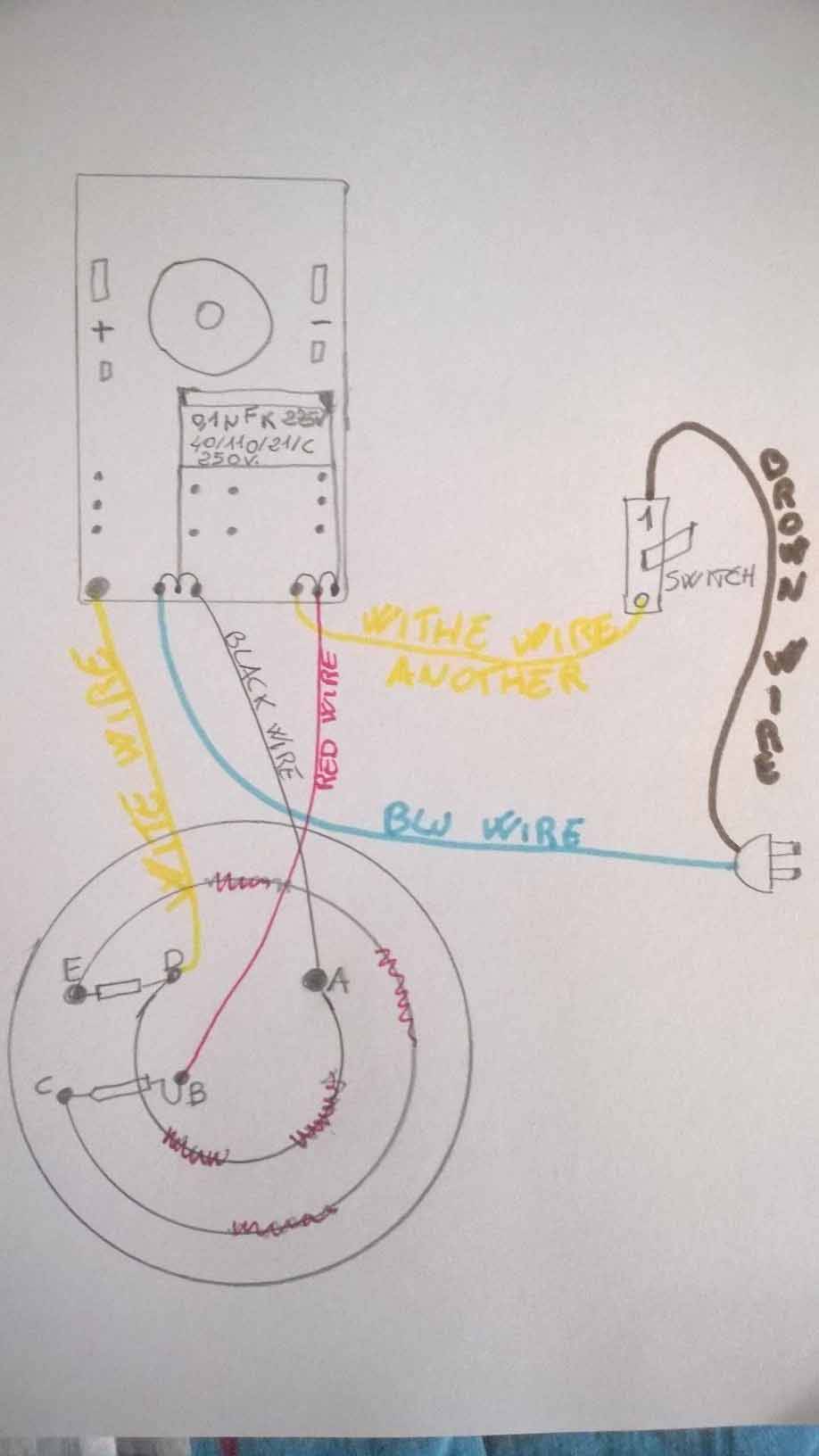
Quote BenKeith wrote: Measure between the white wire and the red wire and between the white wire and the black wire and see what those two values are. Tra il filo bianco e il filo nero ? 6.8 Ohm I add a very basic design On the drawing I have not made, but between the point E and the D point, I made a bridge to bypass the thermal safety
pandiani attached the following image:

Edited by pandiani on 11/17/2016 12:14 PM |
|
|
|
| BenKeith |
Posted on 11/17/2016 2:17 PM
|
|
Pounder Posts: 485 Joined: April 21, 2014 |
I thought you said the overall resistance was 41.5 ohms. Going by your drawing, that would be between the red wire and the black wire on the heater. What you are showing me now shows the overall resistance would be 48.1 ohms. That would make the unit a 1000 Watt and the fan motor would approx. 30 volts. It's looking like you might have to do some voltage measurements for me to be sure but not real sure I want you doing that. How much electrical do you know? It's just not safe for a novice to be poking around inside one of these things with it plugged in and turned on if they are not comfortable with what they are doing. What you bypassed was not the temperature safety. It was the temperature regulator, so it didn't get too hot and burn you popcorn. Since coffee beans roast at a much higher temp than popcorn, it would not get hot enough with that connected. The temperature safety is that silver bullet looking piece, and you do not want to bypass that. |
|
|
|
| pandiani |
Posted on 11/19/2016 6:33 AM
|
|
1/4 Pounder Posts: 74 Joined: November 05, 2016 |
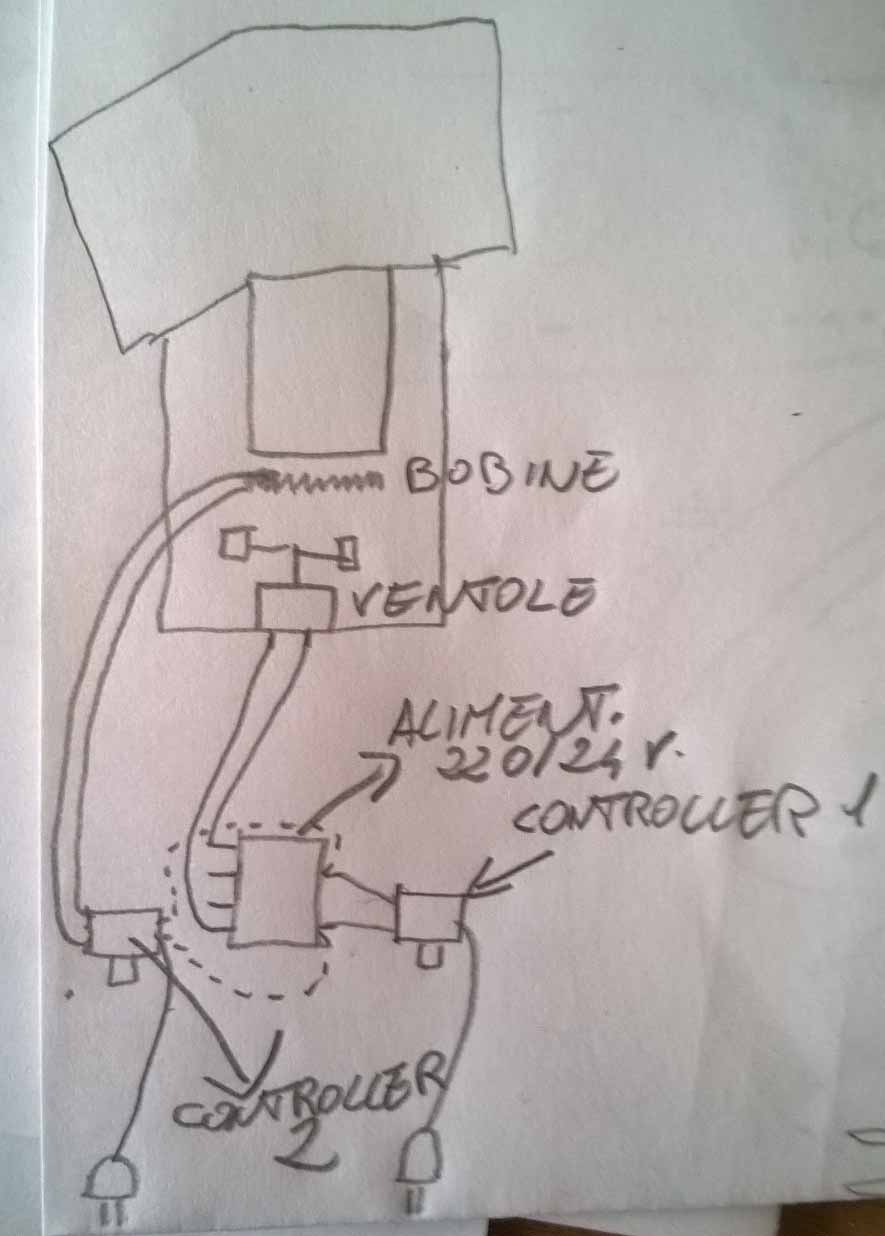
These days I checked out several options, and to use this controller https://www.amazo...B0197MKV0K For what concerns the fan would do so, 220V Controller - Transformer 220/24 - 2A - and the connection (24 V) at the entrance of the section of the diodes motor (bridge rectifier)fan. Now my big doubt, not being an expert, is where to connect the two wires on the motor (diodes). I attach some pictures, a how is my original popper, a think how to change it, one of which I believe to connect the wires to the fan coming from the transformer measuring 4.5 Ohm (here I need your confirmation). As for the coils, keep in mind that, in point E to D, I bypassed the temperature controller, as BenKeith, he would point out. Finally I would use another controller to "control" the coils, and here my reasoning on the wires to be connected, deserves your judgment Coils: the large coil from C to E, the small coil is from A to D is ok? The blue wire is from 220VAC, and goes on the card, with a connecting bridge to the black wire, the black wire goes to the small coil at point A, running tracks along the coil at point D, the point D is a bridge to the eE point, then power is supplied to the large coil, and the current (220VAC) runs from the point C, where there is the fuse, is running the current (220VAC) to the red wire, point B. ? The red wire returning to the card, and here, with a bridge closes the circuit as the white thread (another white thread), which is to connect to the switch. Thus, black wire and the red wire should be the wire that I have to connect the other controller. And I add that, the other white thread, the one that starts at D and goes into the paper, thanks to the diodes, powers the fan. Correct me if I'm wrong Lastly, there is a real need to put the controller to the fan? It will not be always 100%? This seems to me, that just as John said
pandiani attached the following images:

|
|
|
|
| BenKeith |
Posted on 11/19/2016 9:20 AM
|
|
Pounder Posts: 485 Joined: April 21, 2014 |
NO! Do Not do what you are saying in this last post. I will look at it tonight, I don't have time today. |
|
|
|
| btreichel |
Posted on 11/19/2016 11:45 AM
|
|
1/4 Pounder Posts: 187 Joined: May 07, 2007 |
"Lastly, there is a real need to put the controller to the fan? It will not be always 100%?" You would normally split the fan and heater so that you can run the fan for cooling without the heater. On my P1, the first air popper made over here, it was possible to boost the fan to get a larger bean load moving. As the coffee grows about 40% in size and loses up to 15% in weight it would be necessary to reduce the fan power to keep the coffee an heat in the chamber. Remember, you are using the bean mass to control the airflow, and therefore the air temperature. Same heater power, more air, lower temperature. |
|
|
|
| allenb |
Posted on 11/19/2016 1:27 PM
|
 Administrator Posts: 3869 Joined: February 23, 2010 |
Quote pandiani posted: "Lastly, there is a real need to put the controller to the fan? It will not be always 100%?" Quote btreichel posted: "You would normally split the fan and heater so that you can run the fan for cooling without the heater". Some popper fans run at max speed around 18 volts DC, others may need 22 V or higher. You could omit the controller and power the fan with a fixed 24 volts from your transformer but you would most likely be running it too fast or too slow. Better to have a controller and be able to dial in optimum air flow. Cost is minimal and not hard to wire it in. Allen 1/2 lb and 1 lb drum, Siemens Sirocco fluidbed, presspot, chemex, cajun biggin brewer from the backwoods of Louisiana
|
|
|
|
| BenKeith |
Posted on 11/19/2016 2:06 PM
|
|
Pounder Posts: 485 Joined: April 21, 2014 |
Ok, here's what I come up with and would do if I was going to change it. First, you will need: a Hand full of thermal fuses. a Small 18ga power cord to run the fan after mod a 600W dimmer a 2000W dimmer a 220VAC Primary 36VAC 2 or 3 amp secondary transformer A small wire nut or crimp butt connector. A soldering Iron and Resin Core solder Electrical tape or heat shrink Understand also, if you do any modifications on that roaster, that's all on you. I was just saying if it was MINE, this is how I would try to modify it. I'm not saying it's safe, or it's something you should try to do to yours. I take absolutely no responsibility for anything you do with anything you read on here. Take the white wire that goes from the heater to the motor board off the motor board. For now, tape up the end so the bare wire is not exposed but when done and it works you can cut it out all together. Solder one wire from the transformer secondary to the motor board where you disconnected the white wire. Take the Blue and Black wire off the motor board and use the wire nut or butt connector and connect both of those ends together and tape it up so no bare wire is exposed.\ Solder the other wire from the transformer secondary to the motor board where you took the Blue and Black wire off. Connect the 600W dimmer to the primary of the transformer. Connect the 2000W dimmer to the poppers AC power cord. Now this will let you separately control the fan and the heater. Just understand, having the fan on a separate control, if you forget to turn it on or turn it down too slow, you will blow your thermal fuse and trust me, that is going to happen, more than once. Also notice, I meant to say a 36VAC transformer, that's what it's going to take to run that roaster, a 24VAC will make the fan too slow. Let me know when you get ready to do this, I will be checking the news for some Italian that burned his house down or fried himself messing with coffee roaster. |
|
|
|
| allenb |
Posted on 11/19/2016 5:40 PM
|
|
Administrator Posts: 3869 Joined: February 23, 2010 |
Quote BenKeith posted "Connect the 600W dimmer to the primary of the transformer. So, there's not an issue feeding a stepdown transformer with the dimmer's sawtooth waveform output? I remember blowing up a perfectly good 600 watt dimmer feeding a transformer years ago. This was with no load on the secondary. On the other hand, I've seen many seemingly operational circuits posted here with standard light dimmers in conjunction with transformers and I haven't heard of meltdowns. Quote Also notice, I meant to say a 36VAC transformer, that's what it's going to take to run that roaster, a 24VAC will make the fan too slow. Are you aware that some poppers fans are getting anywhere from 18 volts max to 24? Feeding a popper fan that's meant for a max of 18 V could fry or have a short life span at anything over 24. Allen Edited by allenb on 11/19/2016 5:45 PM 1/2 lb and 1 lb drum, Siemens Sirocco fluidbed, presspot, chemex, cajun biggin brewer from the backwoods of Louisiana
|
|
|
|
| BenKeith |
Posted on 11/19/2016 8:49 PM
|
|
Pounder Posts: 485 Joined: April 21, 2014 |
It's entirely possible you may be right. I did it 16 years ago on my first Poppery I started with and didn't have a problem. However, instead of a dimmer, I used a triac circuit I built, but I think most dimmers use a triac. Then again, I might be thinking when I shouldn't be and it may go off like a Fourth of July fireworks display. For right now, I think he needs to just chase one rabbit at the time. Connect the fan to run when the unit is turned on and not try adjusting the speed until he's more comfortable with it. Right now, I'm willing to bet a dollar to a doughnut he blows his thermal fuse where he forgets to turn the fan on. As for the fan voltage, all I have to go by is the readings he gave me off the heater coils. They are being used as a voltage divider and doing the math, it shows the rectifier is being fed with almost 36VAC from the heaters. The only way to tell for sure would be to do actual voltage measurements across the white wire from the heater and the Blue and Black junction on the fan motor board. Ohms law says it's going to be 31 to 35VAC. Also note, those two black cylinder pieces between the rectifier and motor appear to be wire wound resistors. Not knowing the value of those, the fan itself may be running 18 - 24 VDC at the negative and positive terminals on the board. Again, that would require measuring. Measuring voltages in this thing is something I'm not comfortable with having him doing, so I'm having to base everything off what he has provided me and doing the math. Edited by BenKeith on 11/19/2016 8:54 PM |
|
|
|
| allenb |
Posted on 11/20/2016 7:36 AM
|
|
Administrator Posts: 3869 Joined: February 23, 2010 |
Quote ChicagoJohn posted: To replace the power to the blower motor, I used a 50VA 24VAC transformer. While I used a single pole dimmer switch on the primary of the transformer to control the output and thus control the motor speed, I now realize that is not necessary and if I were to do it again, I would just run the motor at full speed and not use the dimmer switch. On my popper, the motor draws about 2.5 amps at 24 VAC so this is why I used a 50VA transformer. With a lower VA rating I tried, the transformer quickly overheated. The transformer case temperature should not exceed 170F (80C). Your system operates at 240 V I think you said. So all of the values will be different but similar principles should apply -- you will have to research that yourself. I went back over John's previous post and see that there shouldn't be an issue feeding pandiani's transformer with a standard dimmer and as you stated "However, instead of a dimmer, I used a triac circuit I built, but I think most dimmers use a triac" they should be built from the same type of circuit structure. John included the dropping resistive element to ensure all of the original heat capacity was replicated when he made his mods. How many watts is that one good for? And, should he include it in this mod? I agree, it would be best if someone could take some as-is state voltage measurements to know for sure what voltage to feed the fan if he decides to forego the fan controller. Allen 1/2 lb and 1 lb drum, Siemens Sirocco fluidbed, presspot, chemex, cajun biggin brewer from the backwoods of Louisiana
|
|
|
|
| BenKeith |
Posted on 11/20/2016 9:49 AM
|
|
Pounder Posts: 485 Joined: April 21, 2014 |
It's not changing the heating element. It will still be using both coils. However, Yes, it will loose the small amount of load the fan circuit is using but have no way of knowing what the parallel resistance is the motor circuit has so it might see some loss in heating power. I'm thinking (doing that again when not used to it) since it's connected to the bridge rectifier it would be 600 ohms or so, which would make minimal difference across that 41.5 ohm winding. That one will have to be determined. If I was doing it, I would just wind me a new 2000W heating element and stick it in there. It's also possible to regain any loss and add even additional power by shorting out windings on the higher resistance element. Again though, if he's not comfortable with making the changes he want's and can't afford to buy another replacement popper if things go south with this one, he should not be making any changes. |
|
|
|

| Jump to Forum: |
Powered by PHP-Fusion Copyright © 2024 PHP-Fusion Inc
Released as free software without warranties under GNU Affero GPL v3
Designed with ♥ by NetriXHosted by skpacman