Login
Shoutbox
You must login to post a message.
renatoa
07/26/2024 3:49 PM
Bill grubbe and Jk, 

allenb
07/26/2024 5:15 AM
Spiderkw Welcome to HRO!


renatoa
07/24/2024 8:31 AM
ramiroflores and John123,

 ?
?

 ?
?renatoa
07/21/2024 1:18 AM
 , Luislobo
renatoa
07/19/2024 11:28 AM
Koepea, 

Forum Threads
Newest Threads
Skywalker roaster modsBackground Roast Iss...
Hello from Arkansas
TC4ESP
Green coffee reviews
Hottest Threads
| Skywalker roaster... | [375] |
| TC4ESP | [115] |
| War on Farmers by... | [47] |
| Adventures in flu... | [26] |
| Hello! (soon) Roa... | [17] |
Donations
Latest Donations
dmccallum - 10.00
JackH - 25.00
snwcmpr - 10.00
Anonymous - 2.00
Anonymous - 5.00
dmccallum - 10.00
JackH - 25.00
snwcmpr - 10.00
Anonymous - 2.00
Anonymous - 5.00
Users Online
Guests Online: 6
Members Online: 0
Total Members: 8,393
Newest Member: Bill grubbe
Members Online: 0
Total Members: 8,393
Newest Member: Bill grubbe
View Thread
Who is here? 1 guest(s)
|
TC4 Shield / Arduino Uno / LCDapter
|
|
| judoclimb |
Posted on 10/17/2017 4:19 PM
|
|
Newbie  Posts: 7 Joined: October 16, 2017 |
Hi. I need help with the LCDapter on Arduino Uno/TC4 shield. I am just starting to learn the Arduino Uno/TC4 shield, so that I can take my coffee roasting to a new level. I have been using analog potentiometers to manually control the heat coil and fan of my customized WB Poppery. My roasting process has consisted of getting readouts from a digital temperature gauge, manually entering in the temperature every 30 seconds, entering the values manually in Excel, and making real-time adjustments to the potentiometer.After extensively reading about the work that others have done on automating this process using a PID, I decided to take a crack at it. What I have currently. - Arduino Uno - TC4 Shield, v6.0 - LCDapter-Complete - Sketch: aArtisanQ-PID v6.3 - Library: aArtisan_STDLib-400 Issue: I have been able to assemble the Arduino/TC4/LCDapter and compile/upload the Sketch using Arduino software via USB connection (nothing else is connected to TC4, such as ZCD, SSRs, or thermocouples). The issue is that the 1) LCD does not turn on, 2) when I run the Serial Monitor > command "chan,1234" > command "read", there is no output. After trying many different things, I can obtain the expected output with the same commands ("# Active channels set to 1234", "77.7, 70.4, 74.4, 74.2,74.9"), ONLY WHEN THE LCDAPTER IS DISCONNECTED. Also, I noticed that the LED on pin 13 of the Arduino board stays on when the LCDapter is connected, but it turns off if it is not connected. Is this an issue, or would this be sorted out once I start connecting the other components like the ZCD, SSRs, and thermocouples? Thanks in advance. |
|
|
|
| greencardigan |
Posted on 10/17/2017 5:31 PM
|
|
1 1/2 Pounder  Posts: 1185 Joined: November 21, 2010 |
Hi and welcome! Have you modified the user.h file in the sketch to suit your setup? Let me know if you need help with the settings in user.h. I would try loading the sketch and running it without the TC4 or LCD connected. It should still respond to the serial commands. Try the READ command and it should respond with a comma separated string of values (which will probably be zeros if no TC4 connected). |
|
|
|
| JackH |
Posted on 10/17/2017 5:35 PM
|
|
Administrator  Posts: 1809 Joined: May 10, 2011 |
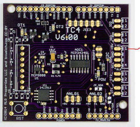
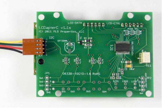
Make sure that you have the 4 pin cable (I2C serial) from the TC4 to the LCDapter plugged in correctly. There is no key to this connector so it can be reversed. Yellow wire is pin 1 and is marked on the TC4 and LCDapter board.
JackH attached the following images:
---Jack
KKTO Roaster. |
|
|
|
| judoclimb |
Posted on 10/18/2017 1:57 AM
|
|
Newbie  Posts: 7 Joined: October 16, 2017 |
Hi Greencadigan, thank you for the reply. Your work on the code and compilation is deeply appreciated! Much respect to you! Hi JackH, thanks! You were absolute right! The I2C serial cable was reversed on the TC4 shield side. I just assumed that the red and black wires go to the +5V and GND terminals (though it doesn't explain why the red wire goes to GND and black wire goes to +5V, now that I think about it). As I look carefully at the TC4 shield board now, BLK and YEL are printed to signify the wire orientation. Now it is wired correctly, I am getting the display to work! See the picture. OK, now on to next steps... (maybe this weekend) |
|
|
|
| JackH |
Posted on 10/18/2017 4:37 AM
|
|
Administrator  Posts: 1809 Joined: May 10, 2011 |
I am glad it helped. Now it is on to the fun part of configuring everything to work! Let us know if you have any questions. ---Jack
KKTO Roaster. |
|
|
|
| judoclimb |
Posted on 10/23/2017 9:58 PM
|
|
Newbie  Posts: 7 Joined: October 16, 2017 |
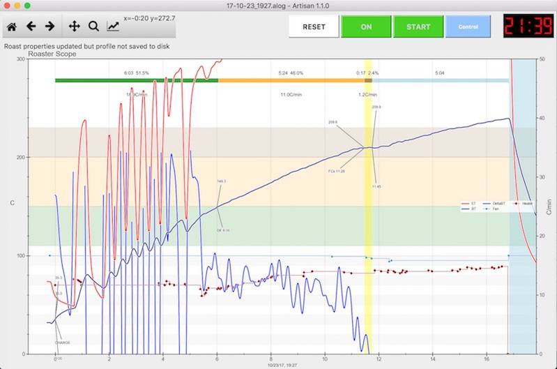
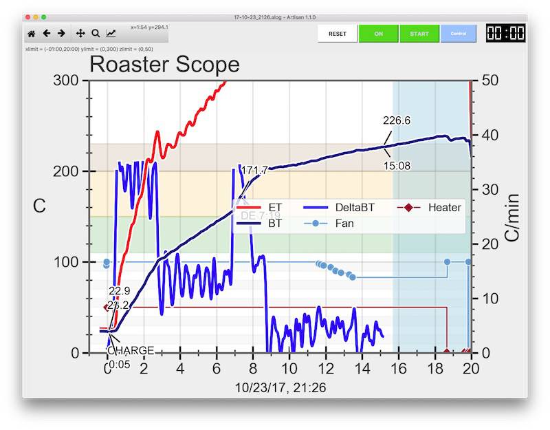
Hi Guys, I hooked up everything, and I did my first few roasts. I couldn't get the Ramp/Soak to work properly. It kept on controlling too high or too low (oscillation between 100 and 0). I gave up, and switched to manual over-ride. Any tips on how to control this? PS. How do you post pictures in here? I have my roaster setup and my oscillating profile that I would like to show you guys.
judoclimb attached the following image:
Edited by judoclimb on 10/23/2017 10:12 PM |
|
|
|
| greencardigan |
Posted on 10/23/2017 10:04 PM
|
|
1 1/2 Pounder  Posts: 1185 Joined: November 21, 2010 |
Sounds like you need to adjust the PID parameters in the Control dialog box. What settings are you using now? See here for posting tips https://forum.hom...?cat_id=16 |
|
|
|
| judoclimb |
Posted on 10/23/2017 10:40 PM
|
|
Newbie  Posts: 7 Joined: October 16, 2017 |
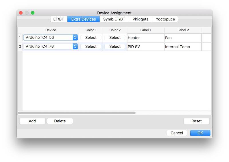
I am currently using the following Ramp/Soak just for starters. I am using Artisan to control it instead of PID Firmware.
judoclimb attached the following images:
|
|
|
|
| greencardigan |
Posted on 10/23/2017 10:56 PM
|
|
1 1/2 Pounder  Posts: 1185 Joined: November 21, 2010 |
If you're not using the Firmware PID then you're using the PID built into Artisan. The ramp soak feature uses either the internal or TC4 PID. Try changing the parameters highlighted in my screenshot attached.
greencardigan attached the following image:
|
|
|
|
| judoclimb |
Posted on 10/24/2017 12:15 AM
|
|
Newbie  Posts: 7 Joined: October 16, 2017 |
Thanks! I was able to stabilize the temperature profile. Next, I will try to find the right profile.
judoclimb attached the following image:
|
|
|
|
| judoclimb |
Posted on 10/24/2017 12:16 AM
|
|
Newbie  Posts: 7 Joined: October 16, 2017 |
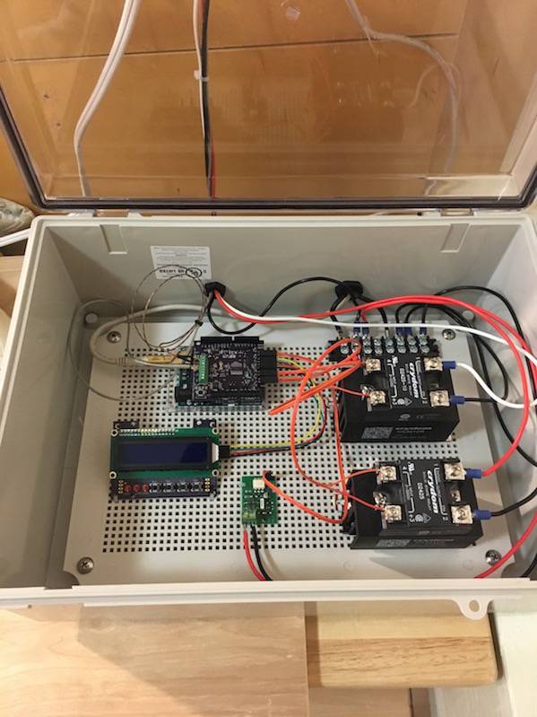
BTW, here is my setup.
judoclimb attached the following images:
|
|
|
|
| Jump to Forum: |
Powered by PHP-Fusion Copyright © 2024 PHP-Fusion Inc
Released as free software without warranties under GNU Affero GPL v3
Designed with ♥ by NetriXHosted by skpacman


