
Login

Shoutbox
You must login to post a message.
renatoa
07/26/2024 3:49 PM
Bill grubbe and Jk, 
allenb
07/26/2024 5:15 AM
Spiderkw Welcome to HRO!

renatoa
07/24/2024 8:31 AM
ramiroflores and John123,

 ?
?
?renatoa
07/21/2024 1:18 AM
 , Luislobo
renatoa
07/19/2024 11:28 AM
Koepea,
Forum Threads
Newest Threads
Skywalker roaster modsBackground Roast Iss...
Hello from Arkansas
TC4ESP
Green coffee reviews
Hottest Threads
| Skywalker roaster... | [375] |
| TC4ESP | [115] |
| War on Farmers by... | [47] |
| Adventures in flu... | [26] |
| Hello! (soon) Roa... | [17] |
In Memory Of Ginny

Donations
Latest Donations
dmccallum - 10.00
JackH - 25.00
snwcmpr - 10.00
Anonymous - 2.00
Anonymous - 5.00
dmccallum - 10.00
JackH - 25.00
snwcmpr - 10.00
Anonymous - 2.00
Anonymous - 5.00
Users Online
Guests Online: 8
Members Online: 0
Total Members: 8,393
Newest Member: Bill grubbe
Members Online: 0
Total Members: 8,393
Newest Member: Bill grubbe
View Thread
Who is here? 1 guest(s)
 Looking for TC4C board
|
|
| Will2 |
Posted on 03/17/2018 4:35 PM
|
 1/4 Pounder  Posts: 154 Joined: March 24, 2015 |
I had several empty PCBs TC4 V6.01, so I mounted parts on them. I also made a few more ZCDs. Write PM. 
Viliam
|
|
|
|
| BenKeith |
Posted on 03/17/2018 9:01 PM
|
|
Pounder  Posts: 485 Joined: April 21, 2014 |
He Will2, sure wish you were in the states. I would send you six and the parts for three if you would solder the parts on three and send those three back to me. I'm still trying to figure out how I'm going to see those 0603 size SMD's without buying one of those high dollar optics of some sort. |
|
|
|
| mg512 |
Posted on 03/22/2018 1:27 PM
|
 1/4 Pounder Posts: 189 Joined: March 04, 2018 |
How many people are there looking for TC4s still, and how much assembly are you comfortable with? If people are happy to give SMD soldering a try (it's not as hard as you'd think), it would be no problem getting bare PCBs; See James211's post above for a link. I can also upload my own version (TC4 plus voltage regulator / buck converter, transistor for DC fan and Bluetooth module). If people want the SMD components soldered already it might be a bit tricky, but if there's more than a handful of units worth of demand then maybe a small assembly run might be possible. If it's less interest than that I might be able to solder a few by hand, but it would be pretty time consuming / expensive. |
|
|
|
| BenKeith |
Posted on 03/22/2018 5:14 PM
|
|
Pounder Posts: 485 Joined: April 21, 2014 |
When I had mine made, I priced having the SMD's installed by the company making the boards. That was going to make the five boards about $37 each. I should be getting mine in the next few days and have most of the parts to assemble three. If they work, if it's legal, and if the sight will let me, once tested and good, I can post the Gerber files and who ever wants can have them some made. Again, that's something that would have to be approved by the moderators on if it would be legal to even do that. I don't care to get into any copy right battles or turf wars over a few little circuit boards. I've had me some made, and that's all I wanted. |
|
|
|
| sethyrish |
Posted on 03/22/2018 10:24 PM
|
|
Newbie  Posts: 24 Joined: January 17, 2018 |
I just had some TC4 V6.01 and LCD adapter board PCB?s made from available information on this site. I used https://jlcpcb.com/. $2 for 10 boards including postage and they look great! All the parts from three suppliers plus overseas postage cost the most. It would be great to have a one shop very specific BOM for those who don?t mind giving SMD soldering a go but aren?t sure of footprints, part substitution etc. Either Mouser or digikey. Or even better a group buy. I guess you need the numbers for that. There?s plenty of information on youtube about SMD soldering so I?m just about ready to take the plunge. Admittedly I did buy myself a Chinese hot air de-soldering gun and bits and pieces to make a cheap Chinese T12 soldering Station Hakko ripoff. |
|
|
|
| mg512 |
Posted on 03/23/2018 8:45 PM
|
|
1/4 Pounder Posts: 189 Joined: March 04, 2018 |
Quote BenKeith wrote: When I had mine made, I priced having the SMD's installed by the company making the boards. That was going to make the five boards about $37 each. I should be getting mine in the next few days and have most of the parts to assemble three. If they work, if it's legal, and if the sight will let me, once tested and good, I can post the Gerber files and who ever wants can have them some made. Again, that's something that would have to be approved by the moderators on if it would be legal to even do that. I don't care to get into any copy right battles or turf wars over a few little circuit boards. I've had me some made, and that's all I wanted. Oh, I missed that earlier. That's actually not too bad - if it works out well for you perhaps we can organise a group order for those still left without boards. Quote I just had some TC4 V6.01 and LCD adapter board PCB?s made from available information on this site. I used https://jlcpcb.com/. $2 for 10 boards including postage and they look great! All the parts from three suppliers plus overseas postage cost the most. It would be great to have a one shop very specific BOM for those who don?t mind giving SMD soldering a go but aren?t sure of footprints, part substitution etc. Either Mouser or digikey. Or even better a group buy. I guess you need the numbers for that. There?s plenty of information on youtube about SMD soldering so I?m just about ready to take the plunge. Admittedly I did buy myself a Chinese hot air de-soldering gun and bits and pieces to make a cheap Chinese T12 soldering Station Hakko ripoff. Aisler.net offers to ship parts along with the PCBs, even labelled for where on the board they go. Might be what you're looking for? They do stencils too. |
|
|
|
| renatoa |
Posted on 03/24/2018 3:33 AM
|
|
Administrator Posts: 3104 Joined: September 30, 2016 |
I am confused why TC4 evolved into SMD... if it were really a desire to encourage people to build theirs, should stay at classic build, the dimensions are imposed by Arduino anyway... |
|
|
|
| mg512 |
Posted on 03/24/2018 8:52 AM
|
|
1/4 Pounder Posts: 189 Joined: March 04, 2018 |
Quote renatoa wrote: I am confused why TC4 evolved into SMD... if it were really a desire to encourage people to build theirs, should stay at classic build, the dimensions are imposed by Arduino anyway... I believe the MCP3424 ADC is only available in SMD packaging. |
|
|
|
| renatoa |
Posted on 03/24/2018 12:16 PM
|
|
Administrator Posts: 3104 Joined: September 30, 2016 |
Sure, I meant resistors and capacitors. |
|
|
|
| mg512 |
Posted on 03/24/2018 12:31 PM
|
|
1/4 Pounder Posts: 189 Joined: March 04, 2018 |
Eh, if you have to do SMD soldering anyway, you might as well have everything that can be SMD assembled already, so people only have to solder the connectors. Respectively for the fully assembled board, SMD keeps the cost down. It shouldn't be too hard to design a PCB that has only the ADC as an SMD component though. |
|
|
|
| BenKeith |
Posted on 03/24/2018 12:56 PM
|
|
Pounder Posts: 485 Joined: April 21, 2014 |
I had thought about doing mine with only the ADC being surface mounted, but the ADC, the eight runs and terminal block and optional Resistors/capacitors use almost half the room on the board, When you start trying to fit all those large through hole components on it, things get very tight and routing things gets complicated. I looked at doing like they did before the SMD days and stand everything on end, but that even got complicated. Already having the built and proven SMD board to go by just made things a whole lot easier. I hate SMD's with a passion because I've gotten too old to see the things well enough to solder, and it's looking like I'm going to have to spend a bunch more money on something to make that possible, so trust me, I would have never made mine SMD's if I could have gotten around it in a reasonable way. Somebody could probably do it, it just was not going to be me. I never liked reinventing the wheel when you had one to go by. Plus, once you get the ADC mounted, that's the hardest part, the resistors and capacitors are a piece of cake compared to the IC's. |
|
|
|
| mg512 |
Posted on 03/24/2018 8:29 PM
|
|
1/4 Pounder Posts: 189 Joined: March 04, 2018 |
On a side note, does anyone know why there is a switch from resistors to capacitors on the thermocouple channels between v5.31 and v6.00? Used to be 10k resistors R8-R15 in v5.31 and earlier, but was replaced by capacitors C5-C12 in V6.00 and up. |
|
|
|
| BenKeith |
Posted on 03/24/2018 8:45 PM
|
|
Pounder Posts: 485 Joined: April 21, 2014 |
All that really changed was the designator, because neither one came installed on the board. They were optional for the user to install as needed. They were probably changed because the capacitors, made a better filter network, plus Ver-7 had four additional caps were added so a band pass filter could be added if needed. It would be up to the user to decide if it was needed and what size capacitors would be needed. If you look at the Version 6 or 7 board, there is just solder on the pads for them, there is no component there. I guess I should also say, those are just my personal thoughts on why. I know in certain situations, thermocouples can need to be filtered because you are only dealing with a few microvolts of signal, and it's very easy to pick up an interference at those signal levels. Edited by BenKeith on 03/24/2018 8:51 PM |
|
|
|
| mg512 |
Posted on 03/24/2018 9:34 PM
|
|
1/4 Pounder Posts: 189 Joined: March 04, 2018 |
Nope, there is actually capacitors installed there on the v7.00 I got from Jim last summer, not just solder pads. Hadn't noticed the four smaller ones before, but those are there as well, caps not just solder pads. Good to know though that they aren't strictly required though, as I didn't put any capacitors on my own board design. Thanks! Back on topic, I could have a go at making a through-hole (except ADC) version of the TC4 board if that would help people. Though as you say, the ADC is the hardest part to solder anyway. |
|
|
|
| BenKeith |
Posted on 03/25/2018 5:58 AM
|
|
Pounder Posts: 485 Joined: April 21, 2014 |
Actually, if you put a bright lite on them and look closely, I think you will see it just looks like they are. I thought the same thing on my 7.01 until I tried to remove one to measure it's value so I would know what size they are. Found out it's hard to remove what ain't there, but I was sure giving it a try. The surface between those two solder pads is just a flat as fritter. I know I was thinking those had to be the thinnest caps I had ever seen but When I took a close up picture of it, I could see very clearly there was nothing there.
BenKeith attached the following image:
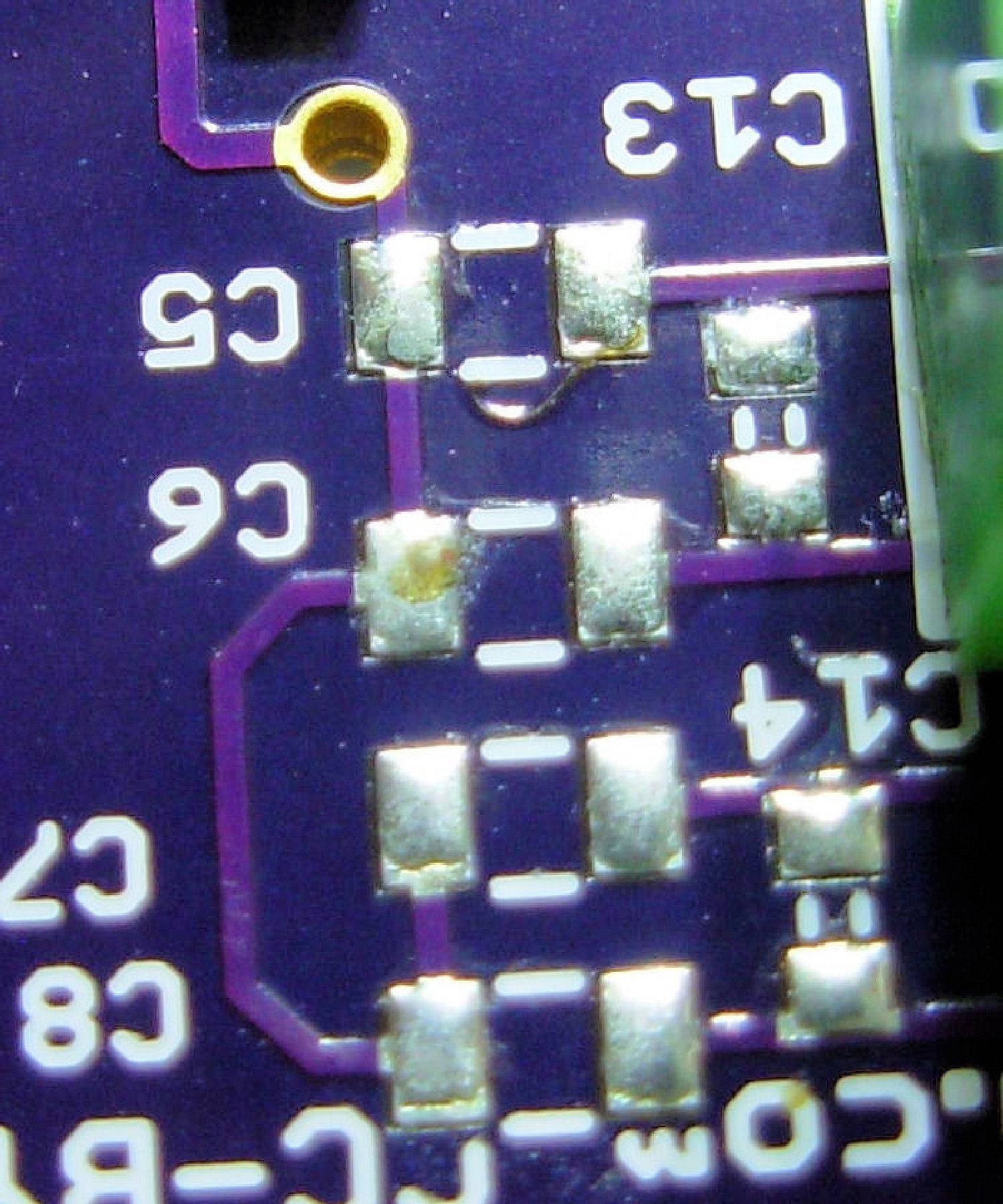
Edited by BenKeith on 03/25/2018 6:07 AM |
|
|
|
| Will2 |
Posted on 03/25/2018 8:09 AM
|
|
1/4 Pounder Posts: 154 Joined: March 24, 2015 |
Quote BenKeith wrote: ... I thought the same thing on my 7.01 ... . You probably write about version 7.00. To some of you I have provided files for version 7.01, eventually I consider the reasons to name this version as 6.02. The difference versus version 6.01 is in the use of 0402 C13-C16 capacitors.  On all the version 6.01 boards that I made, I installed the C13-C16 capacitors 0603 from the bottom of the board, see picture:  Thus, the boards 6.01 and 6.02 are electrically equivalent. Viliam
|
|
|
|
| mg512 |
Posted on 03/25/2018 12:49 PM
|
|
1/4 Pounder Posts: 189 Joined: March 04, 2018 |
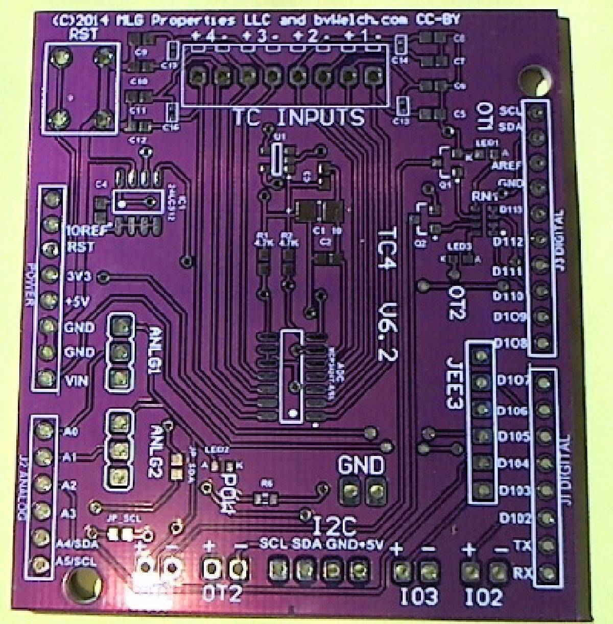
No, I'm pretty sure that's capacitors on my board. Also, I'm completely confused about the different versions of the board now, haha. I thought it was a single lineage of board versions from Jim / Bill Welch, is there other versions too? Are there EAGLE files or similar available for the boards? I've already created my own version from scratch now anyway, but that would have made my life a bit easier... ;)
mg512 attached the following image:

|
|
|
|
| BenKeith |
Posted on 03/26/2018 3:28 AM
|
|
Pounder Posts: 485 Joined: April 21, 2014 |
Yep, yours definitely has caps on it. I guess it depended on what day of the week it was when you got a board from him. I've gotten four or five over the years from 5.3 to 7.01 and none of them have ever had anything on those pads, resistors or caps. I would be interesting to know what value caps he used. I had considered adding 1pf and a 10pf for that small one, but I figure I've never had a problem so why fix what ain't broke. As for different versions, by different people, I think all this interest in making your own has come about from the fact it seems Jim has abandoned them. Like I mentioned before, that's the only reason I've made my own. As for other boards, the only ones I know of are the blank 4.0 board and the 6.0. Edited by BenKeith on 03/26/2018 3:42 AM |
|
|
|
| BenKeith |
Posted on 03/26/2018 3:49 PM
|
|
Pounder Posts: 485 Joined: April 21, 2014 |
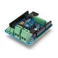
Well, 10 of these finally showed up in the mail today. I picked a color to make them distinct. I was wrong, I looking at that stack and it looked like there were more than 10, They sent 14 for some reason. So, I've got a whole mess of these things.
BenKeith attached the following image:
Edited by BenKeith on 03/26/2018 4:04 PM |
|
|
|
| sethyrish |
Posted on 03/27/2018 1:04 AM
|
|
Newbie Posts: 24 Joined: January 17, 2018 |
Viliam, Can you tell me what value C13-C16 capacitors 0603 from the bottom of the board are? I don't believe they're on your BOM. |
|
|
|
| Will2 |
Posted on 03/27/2018 4:23 AM
|
|
1/4 Pounder Posts: 154 Joined: March 24, 2015 |
Quote sethyrish wrote: ..what value C13-C16 capacitors 0603 from the bottom of the board are?... Same as C6-C12. But no effect was observed in my assembly. Viliam
|
|
|
|
| BenKeith |
Posted on 03/29/2018 4:16 PM
|
|
Pounder Posts: 485 Joined: April 21, 2014 |
Just learned the hard way, if you plan to buy a blank board and build your own, when you order the MCP9800 Temp Sensor, make sure you get the MCP9800 (A0) and not one of the other A1-A7. Those A0-A7 sufixes are the preset I2C Address. Digikey carries two the A0 and the A5, so I had a 50/50 chance of getting the wrong one, and I did. The MCP9800A5T was the first one listed so I ordered it, didn't see any difference in the discriptions listed so that's the one I got. Now I've learned the differnce. The A5 has a I2C hex address of 0X4D The A0 has a I2C hes address of 0X48 The HEX address of 0X48 is what's in the TC4 My temp readings are stuck in Centigrade and I'm thinking that's why. At least I'm hoping that's why because I don't see anything else. I live in the US and have to do the math everytime I see one of those "C" temp numbers. Now, if someone knows where/how to change the I2C address for the 9800 in the program, I would appreciate them telling me, I have this sensore mounted on three boards and two more waiting to be mounted, |
|
|
|
| mg512 |
Posted on 03/29/2018 5:12 PM
|
|
1/4 Pounder Posts: 189 Joined: March 04, 2018 |
There should be a line Code Download source
in the main Arduino sketch. Try replacing A_ADC with the address? Otherwise have a look in cADC.h, that seems to handle most of the MCP3424. |
|
|
|
| Will2 |
Posted on 03/29/2018 5:30 PM
|
|
1/4 Pounder Posts: 154 Joined: March 24, 2015 |
Quote BenKeith wrote: ...where/how to change the I2C address for the 9800 ... Change line 162 in cADC.h, but you can do it only for yourself. Viliam
|
|
|
|
| mg512 |
Posted on 03/29/2018 5:43 PM
|
|
1/4 Pounder Posts: 189 Joined: March 04, 2018 |
Ah, right, it's about the MCP9800 not the 3424. Sorry about that. Will2 obviously has the right answer. |
|
|
|

| Jump to Forum: |
Powered by PHP-Fusion Copyright © 2024 PHP-Fusion Inc
Released as free software without warranties under GNU Affero GPL v3
Designed with ♥ by NetriXHosted by skpacman