
Login

Shoutbox
You must login to post a message.
renatoa
07/26/2024 3:49 PM
Bill grubbe and Jk, 
allenb
07/26/2024 5:15 AM
Spiderkw Welcome to HRO!

renatoa
07/24/2024 8:31 AM
ramiroflores and John123,

 ?
?
?renatoa
07/21/2024 1:18 AM
 , Luislobo
renatoa
07/19/2024 11:28 AM
Koepea,
Forum Threads
Newest Threads
Skywalker roaster modsBackground Roast Iss...
Hello from Arkansas
TC4ESP
Green coffee reviews
Hottest Threads
| Skywalker roaster... | [375] |
| TC4ESP | [115] |
| War on Farmers by... | [47] |
| Adventures in flu... | [26] |
| Hello! (soon) Roa... | [17] |
In Memory Of Ginny

Donations
Latest Donations
dmccallum - 10.00
JackH - 25.00
snwcmpr - 10.00
Anonymous - 2.00
Anonymous - 5.00
dmccallum - 10.00
JackH - 25.00
snwcmpr - 10.00
Anonymous - 2.00
Anonymous - 5.00
Users Online
Guests Online: 7
Members Online: 0
Total Members: 8,394
Newest Member: Bill grubbe
Members Online: 0
Total Members: 8,394
Newest Member: Bill grubbe
View Thread
Who is here? 2 guest(s)
 TC4+ Arduino coffee roaster shield (TC4-compatible)
|
|
| mg512 |
Posted on 08/18/2019 3:24 PM
|
 1/4 Pounder  Posts: 189 Joined: March 04, 2018 |
Quote tyrtok wrote: anyone got Artisan's 'follow background profile' to work with this? considering replacing the current fuji pxg4 with this. Yep, follow-background-profile aka PID control works with the TC4+. I have pretty much always been using it exclusively that way, I don't think I've ever done a single roast manually. As renatoa points out, some people have been struggling getting the PID tuned properly with both the TC4 and TC4+ (same software, same PID algorithm), but for others including me it worked almost immediately. Once it's set up, it works pretty solidly, though I don't have any first-hand experience with the PXG4 so can't comment on how it compares to that. |
|
|
|
| renatoa |
Posted on 08/19/2019 1:35 AM
|
|
Administrator Posts: 3104 Joined: September 30, 2016 |
Curious to see what means works immediately, and how looks the RoR for such roast. Not trying to make a nitpick exercise, but the only way to make the curves looking nice is to apply huge amounts of filtering in Artisan and/or TC4. These filtering will introduce delays in actual value reading, For example, the following TC4 filtering values 50, 66, 75, 80... means delays of 1, 2, 3, 4 seconds of the display value versus the process value. The actual level of measurement methods used is simply unable to provide satisfactory data for the precision of observation claimed by some people when discussing about flic-flaks and other RoR somersault. I can demonstrate mathematically that simply variations within the limits of a 0.1 C degrees temperature band, will produce RoR variations bigger than 10%, i.e. when we read a 10 C / minute RoR value actually this could be anything in the 8-12 band. This is not a TC4 or anything other measurement method defect, but simple math, er... statistics, mean average and such... Next factor that wasn't been discussed anywhere so far is precision of control. 1% step in power for a hot air machine is 6-7 C degrees variation for air temperature. How much is the impact of this value on beans depends a lot on machine build and thermal inertia. But surely this is not a smooth control... especially on IR machines, where radiation variation is instant, as is the light. Edited by renatoa on 08/19/2019 2:01 AM |
|
|
|
| chmod755 |
Posted on 09/15/2019 5:30 PM
|
|
Newbie  Posts: 10 Joined: March 31, 2019 |
Quote mg512 wrote: Quote renatoa wrote: Using AWRITE you should also pay attention to the frequency of generated PWM, if it is appropriate for the equipment being controlled. Oh, that's a good point, thank you for catching that. chmod755, you should probably be fine if you put the valve on IO3, and the PWM dimmer board on one of the standard PWM pins (e.g. IO6) with the AWRITE command. Thanks for taking a long time to write back, but this suggestion worked. I have my PWM fan controller on a standard PWM pin and the Clippard EVPD driver board on IO3. Second question: I want to be able to use two pots (one for fan, one for gas) as analog inputs to control fan and gas output. The original TC4 had analog inputs but the TC4 doesn't. Do I need to customize the code to in my case? |
|
|
|
| renatoa |
Posted on 09/16/2019 1:16 AM
|
|
Administrator Posts: 3104 Joined: September 30, 2016 |
Nope, the analog pins are there, just connect the pots to same ADC ports as for TC4. |
|
|
|
| mg512 |
Posted on 09/16/2019 2:57 AM
|
|
1/4 Pounder Posts: 189 Joined: March 04, 2018 |
Quote [url=https://homeroasters.org/forum/viewthread.php?thread_id=5562&pid=69415#post_69415] Thanks for taking a long time to write back, but this suggestion worked. I have my PWM fan controller on a standard PWM pin and the Clippard EVPD driver board on IO3. Second question: I want to be able to use two pots (one for fan, one for gas) as analog inputs to control fan and gas output. The original TC4 had analog inputs but the TC4 doesn't. Do I need to customize the code to in my case? Pots still work on the TC4+ - while there aren't separate headers for analog inputs, the corresponding pins are still there. You can connect the pots directly to them: The middle pin of the pot connects to pin A0 respectively A1 on the Arduino header (the long rows of headers on the side of the shield, that also connect to the Arduino underneath the shield). The outer pins connect to +5V and GND, also present on the Arduino header. No need for any modification in the code. |
|
|
|
| chmod755 |
Posted on 09/16/2019 7:52 AM
|
|
Newbie Posts: 10 Joined: March 31, 2019 |
Quote mg512 wrote: Quote [url=https://homeroasters.org/forum/viewthread.php?thread_id=5562&pid=69415#post_69415] Thanks for taking a long time to write back, but this suggestion worked. I have my PWM fan controller on a standard PWM pin and the Clippard EVPD driver board on IO3. Second question: I want to be able to use two pots (one for fan, one for gas) as analog inputs to control fan and gas output. The original TC4 had analog inputs but the TC4 doesn't. Do I need to customize the code to in my case? Pots still work on the TC4+ - while there aren't separate headers for analog inputs, the corresponding pins are still there. You can connect the pots directly to them: The middle pin of the pot connects to pin A0 respectively A1 on the Arduino header (the long rows of headers on the side of the shield, that also connect to the Arduino underneath the shield). The outer pins connect to +5V and GND, also present on the Arduino header. No need for any modification in the code. Thanks for replying. I want to use two pots though. One controlling IO3 and one controlling the output on D06. Where do I put the second pot? |
|
|
|
| renatoa |
Posted on 09/16/2019 9:44 AM
|
|
Administrator Posts: 3104 Joined: September 30, 2016 |
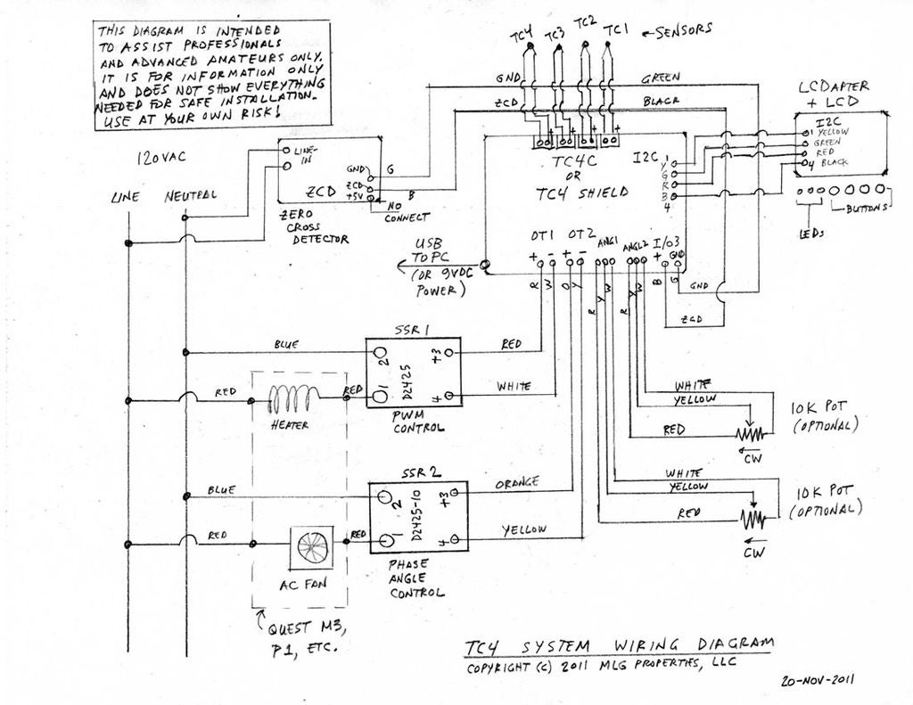
Quote ...Pots still work on the TC4+ - while there aren't separate headers for analog inputs, the corresponding pins are still there. You can connect the pots directly to them: The middle pin of the pot connects to pin A0 respectively A1 on the Arduino header (the long rows of headers on the side of the shield, that also connect to the Arduino underneath the shield). One pot on A0, the other on A1. I mean the middle pins of each pot to each corresponding analog pin. As in the attached uber classic TC4 wiring schematic. ...
renatoa attached the following image:
|
|
|
|
| chmod755 |
Posted on 09/16/2019 10:52 AM
|
|
Newbie Posts: 10 Joined: March 31, 2019 |
Quote renatoa wrote: Quote ...Pots still work on the TC4+ - while there aren't separate headers for analog inputs, the corresponding pins are still there. You can connect the pots directly to them: The middle pin of the pot connects to pin A0 respectively A1 on the Arduino header (the long rows of headers on the side of the shield, that also connect to the Arduino underneath the shield). One pot on A0, the other on A1. I mean the middle pins of each pot to each corresponding analog pin. As in the attached uber classic TC4 wiring schematic. ... How does the arduino program know that one of the pots is controlling the output of D06? Does it need to be specified somewhere? |
|
|
|
| renatoa |
Posted on 09/16/2019 11:45 AM
|
|
Administrator Posts: 3104 Joined: September 30, 2016 |
The pot on A0 controls the heater, if your heater control pin (OT1 in user.h) is set to D06, then you are set. The pot on A1 controls the fan, which is a phase angle control job, not PWM, as is IO3... so I see here some code change needed... |
|
|
|
| mg512 |
Posted on 09/17/2019 1:13 AM
|
|
1/4 Pounder Posts: 189 Joined: March 04, 2018 |
Quote chmod755 wrote: How does the arduino program know that one of the pots is controlling the output of D06? Does it need to be specified somewhere? Oh, right, you have that slightly unusual setup with two PWM outputs. Then it does require a small amount of code change. Assuming you have set the configuration to PWM mode in user.h, the second potentiometer should alreadly control IO3. The first pot however by default will control OT1. I don't think simply changing the OT1 pin in user.h as renatoa suggests would help, since you're using standard Arduino PWM on that pin, not the aArtisan-specific slow PWM that's used on OT1 usually. Instead, go into the main Arduino sketch file, and look for the function Code Download source void readAnlg1() Code Download source #else // PWM Mode Replace Code Download source outOT1(); Code Download source analogWrite(6,(int)(reading*2.55)); I think that should do the trick. Do test it and let us know how it goes. |
|
|
|
| ROSTARN |
Posted on 12/08/2019 4:24 AM
|
|
Newbie Posts: 13 Joined: April 06, 2018 |
Hi I got your TC4+ shield and I use USB to connect to the arduino. I also want to use the onboard mosfet but when I do the arduino becomes unstable and freezes. It seems like the cause is when using both USB and DC input, 12v in my case, the arduino becomes very unstable, when using only usb I have stability. For my setup I think I need to remove the voltage regulator to separate usb 5v and the DC input. My suggestion is that there should be a jumper that separates the two power sources. |
|
|
|
| mg512 |
Posted on 12/08/2019 6:22 AM
|
|
1/4 Pounder Posts: 189 Joined: March 04, 2018 |
That is odd. Is that happening with a DC load connected (and perhaps turned on) as well? Or is just a 12V present on DC IN already enough to cause the issue? Is the USB plugged into a computer that's on mains power, or a laptop that's running on battery? |
|
|
|
| JackH |
Posted on 12/08/2019 7:38 AM
|
 Administrator Posts: 1809 Joined: May 10, 2011 |
I don't know if this applies to the TC4+ design but I remember a problem with original TC4 weirdness and grounding when using an external DC source. JimG had suggested to add a jumper wire from the TC4 ground to a good ground source. Not sure if this is correct for this situation, just a thought. I think it was for ground loop trouble and metal sheathed probes. Also, did you try another DC source? Edited by JackH on 12/08/2019 9:35 AM ---Jack
KKTO Roaster. |
|
|
|
| ROSTARN |
Posted on 12/08/2019 10:06 AM
|
|
Newbie Posts: 13 Joined: April 06, 2018 |
I did have a TC4 before with the same setup and it was rock solid. Then unfortunately I short circuit it by accident four months ago and I've been struggling since with replacing component after component. Now I have been switching out all components and the only difference now is the TC4+. Firmware is the latest release 6.7 Its enough to have DC IN present and I am using a laptop. I have two arduinos and the same problem on both so that can be ruled out. I did try the grounding trick JACKH but it didnt help. And I just switched the DC source to a brand new Mean Well PSU, no improvement. The roast machine itself is grounded and so is the AC fan connected. Anyway, when bypassing the onboard mosfet the arduino is stable. But It runs for sometimes an hour then suddenly I get this message above the scope in Artisan " Exception: ser.ARDUINOTC4temperature(): could not convert string to float: @line 42721" And then it stops reading the temperature and controls the connection to the arduino is lost. The only thing left to switch is the thermocouples This never ending problems is driving me crazy.. 
ROSTARN attached the following image:

Edited by ROSTARN on 12/08/2019 10:11 AM |
|
|
|
| mg512 |
Posted on 12/09/2019 4:52 AM
|
|
1/4 Pounder Posts: 189 Joined: March 04, 2018 |
Grounding can be an issue, but mostly I have seen that happened when the USB host was also connected to AC, never with a laptop on battery. I've only ever seen it cause a little noise in the temperature readings, not affect system stability. I suppose it's possible in this case with the extra AC components, ZCD and AC fan, that there are a few extra ground paths. Rostarn, I am a little confused now. The issue you're describing in your last post is a different issue than before, am I understanding that correctly? Could we take a step back and go throught it all in more detail? Before, with both the MOSFET and voltage regulator in place, how exactly did instability manifest? Did the Arduino reset randomly, or something else? Did you try desoldering only the voltage regulator, but leaving the MOSFET in place, and how did that affect things? When you had the plain TC4, did you control the DC load with that too? If so, how? And were there any problems with that? With the new problem, are you saying you are not using the DC driver at all now, as in, nothing connected to DC IN or DC OUT on the TC4+? Or that you desoldered the MOSFET completely? Or did you mean the voltage regulator? The error message sounds like Artisan is getting some unexpected response from the Arduino when it sends a READ command. Try enabling the serial log by going to Help -> Serial, ticking serial log on, and keep that window open. Once the issue occurs, what's written in that window? |
|
|
|
| ROSTARN |
Posted on 12/10/2019 2:58 PM
|
|
Newbie Posts: 13 Joined: April 06, 2018 |
Oh Man! I found that one wire to one thermocouple was a little loose so i tighten it. And voila the instability is gone. I confirmed it by removing and inserting the wire again while it was on and the arduino froze up again like before with the same error message in artisan as in previous post. I did capture it in serial monitor but nothing really useful to see. I post it anyways if someone is interested: 982 21:08:07.008 ArduinoTC4: COM4,115200,8,N,1,1.0 || Tx = READ || Rx = ['']|| Ts= -1.00, -1.00, 0.00, 0.00, 0.00, 0.00 981 21:08:03.497 ArduinoTC4: COM4,115200,8,N,1,1.0 || Tx = READ || Rx = ['']|| Ts= -1.00, -1.00, 0.00, 0.00, 0.00, 0.00 980 21:08:01.989 ArduinoTC4: COM4,115200,8,N,1,1.0 || Tx = READ || Rx = ['27.4', '78.1', '48.8', '32.1', '35.2', '0', '0', '0']|| Ts= 78.10, 48.80, 27.40, 35.20, 0.00, 0.00 979 21:08:00.483 ArduinoTC4: COM4,115200,8,N,1,1.0 || Tx = READ || Rx = ['27.4', '78.1', '48.8', '32.1', '34.7', '0', '0', '0']|| Ts= 78.10, 48.80, 27.40, 34.70, 0.00, 0.00 There is no issue now running both power sources. I didnt remove anything from the board yet so its all stock tc4+. DC in and out are also connected. What I did before was connecting an external mosfet circuit through the io3 pins, as I did on the TC4 setup. No power connected to DC IN, bypassing the onboard mosfet and voltage regulator. It seemed like it fixed the problem but in reality I was probably just touching the thermocouple wire a little so it made contact for a while and later vibrations loosened it again. Makes sense now. Hopefully I dont speak too soon and the problems come back. (has happened many times before) Just a thought: if its that sensitive why not having caps in series and parallel on the thermocouples channels as the tc4 does? I did notice the temperature was swinging more than on the tc4, although not noticeable when increasing the post filtering by 10%. Most people (myself included) cant choose a suiting cap or know where to buy one. You have the solder pads ready and it would become a better product. Thanks a lot for the help guys, feels good knowing there is support here  |
|
|
|
| mg512 |
Posted on 12/11/2019 7:47 AM
|
|
1/4 Pounder Posts: 189 Joined: March 04, 2018 |
Oh, happy to hear you solved it. Still a little odd, a loose TC wire shouldn't trip up the Arduino as a whole. Is it possible the wire (or its metal shielding) was touching elsewhere and creating a short? I don't think the original TC4 had those capacitors as standard, at least as far as I know. I intentionally don't solder any by default so that users have the most flexibility - as you observe software filtering can achieve the same effect, but then you can turn it off. On my own setup I prefer little or no filtering, for instance. I could populate them in the next batch though if people would prefer that. |
|
|
|
| JackH |
Posted on 12/11/2019 8:26 AM
|
|
Administrator Posts: 1809 Joined: May 10, 2011 |
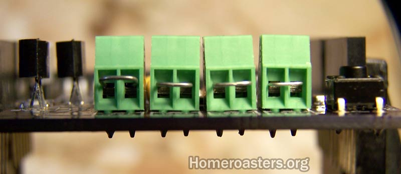
I am glad it is working! Thanks to mg512 for helping with this! I believe JimG left the capacitors optional on later TC4 designs. Pads were there to add them I think. One of the troubleshooting/testing procedures I did when building the older TC4 was to temporarily jumper the TC inputs (+ to -). This would allow me to test all inputs (the temperature read should be about ambient).
JackH attached the following image:
---Jack
KKTO Roaster. |
|
|
|
| renatoa |
Posted on 12/11/2019 9:17 AM
|
|
Administrator Posts: 3104 Joined: September 30, 2016 |
Quote mg512 wrote: ...Still a little odd, a loose TC wire shouldn't trip up the Arduino as a whole. Is it possible the wire (or its metal shielding) was touching elsewhere and creating a short? ... It's possible, the ADC is the culprit, any channel that is not used must be grounded, or inputs shorted, else will hit the MCU, even ESP. Sounds odd, but the inputs of an unused channel, if left floating, can influence readings of other channel, or even reset the whole board ! |
|
|
|
| ROSTARN |
Posted on 12/11/2019 1:20 PM
|
|
Newbie Posts: 13 Joined: April 06, 2018 |
Thats interesting, I will from now on short my unused channels and maybe something to put in your guide for TC4+? The TC4 I have is from member Will2 and that had caps everywhere on the channels. If I had the knowledge of which caps and where to buy them, I would. Can anyone recomend, preferbly within EU? |
|
|
|
| greencardigan |
Posted on 12/11/2019 4:29 PM
|
 1 1/2 Pounder  Posts: 1185 Joined: November 21, 2010 |
I use 10000PF 50V X7R caps on the TC4 boards I build. The TC4 uses a mix of 0603 and 0402 sizes but Matthias could confirm what size has been allowed for on the TC4+ boards. Here are links to the actual caps I've been using at Digikey. CAP CER 10000PF 50V X7R 0603 CAP CER 10000PF 50V X7R 0402 |
|
|
|
| renatoa |
Posted on 12/13/2019 7:21 AM
|
|
Administrator Posts: 3104 Joined: September 30, 2016 |
You have attached a typical TC amp input filtering that kills any noise, even at 0.012 C resolution ! Consider there is a BT dongle at 5 cm from TC amp/ADC boards
renatoa attached the following image:

Edited by renatoa on 12/13/2019 7:28 AM |
|
|
|
| mg512 |
Posted on 12/17/2019 9:57 AM
|
|
1/4 Pounder Posts: 189 Joined: March 04, 2018 |
Odd, I have always left my inputs floating, and have never had any issues with that. I'll have a look at this for future revisions though and do some testing. The BT module shouldn't create any interference in my experience, much too high frequency. The capacitor pads on the TC4+ are all 0603-size, if anyone wants to add caps. The ones that greencardigan linked should work. You'd need 12 of the 0603 ones (get a few extra, you will drop one on the floor and never find it again... ;)) |
|
|
|
| ROSTARN |
Posted on 12/21/2019 4:11 AM
|
|
Newbie Posts: 13 Joined: April 06, 2018 |
Update I ran the machine for almost three hours yesterday and got two freeze ups after maybe an hour each time during warmup and idling, same as before. Fortunatly I managed to do two roasts during this time with no problem, except I had to raise the fan speed on ot2 by 5-7% to get the same speed as on tc4 setup. I did shorten the unused thermocouples channels but that didnt help in my case. As my setup is electric drum roaster with dc drum motor on io3 I need it to run stable for hours. As a next move I will solder caps kindly provided by greencardigan on the solderpads and hope it will solve this problem, otherwise Im out of ideas. |
|
|
|
| JackH |
Posted on 12/21/2019 7:49 AM
|
|
Administrator Posts: 1809 Joined: May 10, 2011 |
Could there be some electrical interference somewhere? TC4 too close to motor, etc..
---Jack
KKTO Roaster. |
|
|
|

| Jump to Forum: |
Powered by PHP-Fusion Copyright © 2024 PHP-Fusion Inc
Released as free software without warranties under GNU Affero GPL v3
Designed with ♥ by NetriXHosted by skpacman