
Login

Shoutbox
You must login to post a message.
renatoa
07/26/2024 3:49 PM
Bill grubbe and Jk, 
allenb
07/26/2024 5:15 AM
Spiderkw Welcome to HRO!

renatoa
07/24/2024 8:31 AM
ramiroflores and John123,

 ?
?
?renatoa
07/21/2024 1:18 AM
 , Luislobo
renatoa
07/19/2024 11:28 AM
Koepea,
Forum Threads
Newest Threads
Skywalker roaster modsBackground Roast Iss...
Hello from Arkansas
TC4ESP
Green coffee reviews
Hottest Threads
| Skywalker roaster... | [375] |
| TC4ESP | [115] |
| War on Farmers by... | [47] |
| Adventures in flu... | [26] |
| Hello! (soon) Roa... | [17] |
In Memory Of Ginny

Donations
Latest Donations
dmccallum - 10.00
JackH - 25.00
snwcmpr - 10.00
Anonymous - 2.00
Anonymous - 5.00
dmccallum - 10.00
JackH - 25.00
snwcmpr - 10.00
Anonymous - 2.00
Anonymous - 5.00
Users Online
Guests Online: 6
Members Online: 0
Total Members: 8,393
Newest Member: Bill grubbe
Members Online: 0
Total Members: 8,393
Newest Member: Bill grubbe
View Thread
Who is here? 2 guest(s)
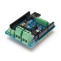
 TC4+ Arduino coffee roaster shield (TC4-compatible)
|
|
| freetwhss |
Posted on 07/20/2018 9:01 PM
|
|
Newbie  Posts: 5 Joined: May 09, 2018 |
Quote KSkip wrote: What are you looking for? The process is pretty straight forward and Matthias is super helpful as well. My first time home roasting was really successful thanks to Matthias and his CR3. See: https://forum.hom...post_66124 Hi https://www.youtube.com/watch?v=gDzR6C7zoV0 Just like above video, at 41 secs show TC4 can be controlled by Artisan. Please take a video show CR3 can be controlled by Artisan. Thank You. |
|
|
|
| mg512 |
Posted on 07/24/2018 11:56 AM
|
 1/4 Pounder  Posts: 189 Joined: March 04, 2018 |
Quote freetwhss wrote: Hi https://www.youtube.com/watch?v=gDzR6C7zoV0 Just like above video, at 41 secs show TC4 can be controlled by Artisan. Please take a video show CR3 can be controlled by Artisan. Thank You. Heya, I've PMed you a short video, let me know if that's what you were after. It's not of a quality that I'd upload anywhere public, but if anyone else wants a look feel free to get in touch. In general, ideally please contact me directly only with orders; for questions etc. post here - that way everyone gets to benefit from the discussion, and some questions other people on here are better placed to answer than I am I think. Plus, the number of questions I've been getting has gone up a fair bit recently, if that trend continues I don't think it'll be feasible for me to answer them all one-on-one. ;) |
|
|
|
| freetwhss |
Posted on 07/24/2018 9:21 PM
|
|
Newbie Posts: 5 Joined: May 09, 2018 |
Thanks, great video.I will order one CR3. |
|
|
|
| samk |
Posted on 07/29/2018 5:49 PM
|
 Newbie Posts: 9 Joined: July 11, 2018 |
Hi, I purchased a CR3 shield from Matthias and i have it working with Artisan using a Hot Air popper. I can control the heater but cant seem to get the fan to respond to a slider. It just goes to full speed one power as applied to the CR3. Queston is in the slider config should i select Serial Command for IO3 or PWM?, Sorry if this should be in its own thread, I was thinking that all CR3 concerns would be better served in one place thanks |
|
|
|
| mg512 |
Posted on 07/30/2018 10:09 AM
|
|
1/4 Pounder Posts: 189 Joined: March 04, 2018 |
Quote samk wrote: Hi, I purchased a CR3 shield from Matthias and i have it working with Artisan using a Hot Air popper. I can control the heater but cant seem to get the fan to respond to a slider. It just goes to full speed one power as applied to the CR3. Queston is in the slider config should i select Serial Command for IO3 or PWM?, Sorry if this should be in its own thread, I was thinking that all CR3 concerns would be better served in one place thanks Hi Sam, What does your setup look like? DC fan, I assume? Using Artisan? Yes, in Artisan you would use the IO3 command, or for some firmware versions there is also a DCFAN command, but you shouldn't need that. Does changing the slider do anything at all? How about if instead you send an IO3 command directly in the Arduino Serial Monitor? Those are the first few things that come to mind - let us know how it goes. |
|
|
|
| samk |
Posted on 07/30/2018 10:58 AM
|
|
Newbie Posts: 9 Joined: July 11, 2018 |
Sorry, Yes Matthias,, Its a Nostalgia Hot Air Popper modified with the Motor and Heater separated. Fan Motor, CR3 and Arduino is powered by a 18vdc PS, with a SSR for the heater circuit. Yes also using Artisan, Arduino has aArtisan.ino REL-300 flashed on it. The Slider does not have any affect on the fan motor which starts up full speed once power is applied to the arduino/CR3. If i change the code for the slider to OT2;{} then the corresponding LED on the CR3 does in fact blink, but if I use IO3;{} then no response. Actually Im not sure if that's the correct code for the DC fan. I wont be able to check using the serial monitor until this evening, is the IO3;{} the correct code structure? hope this helps |
|
|
|
| mg512 |
Posted on 07/30/2018 11:02 AM
|
|
1/4 Pounder Posts: 189 Joined: March 04, 2018 |
Quote samk wrote: Sorry, Yes Matthias,, Its a Nostalgia Hot Air Popper modified with the Motor and Heater separated. Fan Motor, CR3 and Arduino is powered by a 18vdc PS, with a SSR for the heater circuit. Yes also using Artisan, Arduino has aArtisan.ino REL-300 flashed on it. The Slider does not have any affect on the fan motor which starts up full speed once power is applied to the arduino/CR3. If i change the code for the slider to OT2;{} then the corresponding LED on the CR3 does in fact blink, but if I use IO3;{} then no response. Actually Im not sure if that's the correct code for the DC fan. I wont be able to check using the serial monitor until this evening, is the IO3;{} the correct code structure? hope this helps Yep, IO3;{} should be correct. Try IO3;50 in the serial monitor and see if that does anything. If not, the two things I'd try next is a different Arduino sketch (e.g. aArtisanQ_PID), and double checking that you've wired it up correctly (DC fan is attached to DC+ And DC- header on the CR3). |
|
|
|
| greencardigan |
Posted on 07/30/2018 7:13 PM
|
 1 1/2 Pounder  Posts: 1185 Joined: November 21, 2010 |
Did you have a multimeter? I so, you could measure the output on pin 3 of the Arduino to see if the output is changing voltage as you send different IO3 commands. |
|
|
|
| samk |
Posted on 07/30/2018 9:48 PM
|
|
Newbie Posts: 9 Joined: July 11, 2018 |
Yes I do have a Multi-meter greencardigan, checked the out of Pin 3 to ground in both Artisan and the Serial monitor. when slider at Zero and using IO3;0 in the serial Monitor the meter showed 4.1mv, slider at 50% and IO3;50 reading was 2.4vdc and with the slider at 100% and IO3;100, reading was 4.9vdc, So it seems that the arduino is responding to the input from both Artisan and the Serial monitor, I also tried the aArtisanQ_PID Sketch earlier but it displayed the same behavior |
|
|
|
| greencardigan |
Posted on 07/30/2018 10:37 PM
|
|
1 1/2 Pounder Posts: 1185 Joined: November 21, 2010 |
OK, it sounds like the software side is working properly. Maybe double check your connections or post a photo showing your connections. |
|
|
|
| samk |
Posted on 07/31/2018 6:42 AM
|
|
Newbie Posts: 9 Joined: July 11, 2018 |
Thank you again for your input, I'll check the connections this evening when i get home. Seems to me that since the fan comes on and continues to run full speed when power is applied to the boards that the wiring from the terminal strip to the fan motor is correct, Would the polarity of the flyback diode cause any problems? if I reverse the leads on the output from the board to the fan motor then it wont start nor will changing the slider have any affect. thanks again, sam |
|
|
|
| mg512 |
Posted on 07/31/2018 6:56 AM
|
|
1/4 Pounder Posts: 189 Joined: March 04, 2018 |
Quote samk wrote: Thank you again for your input, I'll check the connections this evening when i get home. Seems to me that since the fan comes on and continues to run full speed when power is applied to the boards that the wiring from the terminal strip to the fan motor is correct, Would the polarity of the flyback diode cause any problems? if I reverse the leads on the output from the board to the fan motor then it wont start nor will changing the slider have any affect. thanks again, sam If you used a Zener across the MOSFET, that would be a possibility. But with a regular diode across the motor terminals reversing it should give you a short when turning on the motor. Could you check the left leg of the MOSFET to ground with your multimeter, when you put IO3;0? And then maybe middle to right leg and left to right leg? Thank you! |
|
|
|
| samk |
Posted on 07/31/2018 7:58 AM
|
|
Newbie Posts: 9 Joined: July 11, 2018 |
Sure will, the diode was a 1N4007 i believe, I'll check it all out this evening thank you, sam |
|
|
|
| samk |
Posted on 07/31/2018 8:24 PM
|
|
Newbie Posts: 9 Joined: July 11, 2018 |
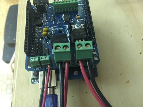
Hi Matthias, I checked the voltages as you asked, the Arduino/CR3 is supplied with 18.7vc from a laptop PS Left leg of the MOSFET to ground was 14.9mv Middle leg to right leg was .45vdc Left lg to right leg was 8.8mv also added Pics of board and fan motor connections thank you, sam
samk attached the following images:

|
|
|
|
| mg512 |
Posted on 08/01/2018 3:18 AM
|
|
1/4 Pounder Posts: 189 Joined: March 04, 2018 |
Quote samk wrote: Hi Matthias, I checked the voltages as you asked, the Arduino/CR3 is supplied with 18.7vc from a laptop PS Left leg of the MOSFET to ground was 14.9mv Middle leg to right leg was .45vdc Left lg to right leg was 8.8mv also added Pics of board and fan motor connections thank you, sam And that's with the fan spinning? And presumably middle leg to ground would be about 18V, right? I can think of two possibilities: 1. The MOSFET is damaged. 2. There is a short between middle and right leg somewhere on the PCB. You would likely be able to see that, e.g. if there's solder connecting the two legs on the bottom side of the PCB. Either way it sounds like a hardware defect with the board. If you happen to have a soldering iron and don't mind replacing the MOSFET yourself you could give that a try. Otherwise I will mail you a new board. |
|
|
|
| samk |
Posted on 08/01/2018 6:10 AM
|
|
Newbie Posts: 9 Joined: July 11, 2018 |
I was thinking that there was an issue with the MOSFET, so I ordered some a few days ago, they should be here today and ill Swap it out, I didn't check middle leg to ground but i will when i get home, and yes the fan was running with those readings sam |
|
|
|
| samk |
Posted on 08/01/2018 6:55 PM
|
|
Newbie Posts: 9 Joined: July 11, 2018 |
Hi Matthias, Good News!!! I replaced the MOSFET today when I got home and now the fan speed can be controlled by Artisan, Thanks for your Patience!! Also Thanks to greencardigan AKA Brad for his input as well. sam |
|
|
|
| mg512 |
Posted on 08/04/2018 10:46 AM
|
|
1/4 Pounder Posts: 189 Joined: March 04, 2018 |
Oh, I am very happy to hear you got it sorted! Just out of curiosity, can you think of anything that happened when you set up the board that might have damaged the MOSFET? This is actually the second time that has happened in just over a dozen boards; the other time we assumed it happened during assembly, but this time I assembled the board and tested the MOSFET before I mailed it to you. If the MOSFETS are so sensitive to ESD I will have to look into that. I'll in any case refund you a part of the order for your trouble and to cover the cost of the new transistor; However it got damaged, this is obviously not the robustness I am aiming for. |
|
|
|
| samk |
Posted on 08/04/2018 11:48 AM
|
|
Newbie Posts: 9 Joined: July 11, 2018 |
The only thing I do know was having the polarity of the flyback diode wrong, The fan wouldn't come on initially, I swapped the leads at the terminal strip and the the motor came on without any control. I then took an re soldered the leads and diode so the red and black leads were correct along with the diode (which when I double checked I saw the polarity was reversed) . At that point I think whatever happened was already done and the fan would only run full speed. Please there is no reason for a refund, I apologize that whatever i did caused a problem sam |
|
|
|
| mg512 |
Posted on 08/04/2018 1:24 PM
|
|
1/4 Pounder Posts: 189 Joined: March 04, 2018 |
Ahhh, yes, that would create a short, which could have damaged the MOSFET. Still a little surprised, as the IRF540N is rated for 33A continuous current, so I'd expect the power supply to go long before the MOSFET. ;) And no need to apologise, that's actually very good feedback - clearly there should be a prominent warning about this in the manual. ;)) Anyway, happy to hear it's sorted.  Let us know how the roasting goes. Let us know how the roasting goes. |
|
|
|
| Wiz Kalita |
Posted on 08/07/2018 3:09 AM
|
|
Newbie Posts: 49 Joined: August 06, 2018 |
How much power can the DC fan driver supply? My fan takes 20V and 2A, so I already burned through some L298N boards due to the 3-4V voltage drop. |
|
|
|
| mg512 |
Posted on 08/07/2018 3:28 AM
|
|
1/4 Pounder Posts: 189 Joined: March 04, 2018 |
Good question. Short answer: 20V and 2A will be fine, in fact it's what the board is made for. ;) I have been running mine with 24V 2A. In theory you should be good to about 28V 2A without a heatsink, or 28V 4A with a small heatsink on the IRF540N. Long answer: It depends. Voltage is limited mostly by the voltage regulator for the Arduino, the R-78E5.0 that the board comes with by default takes up to 28V. There's regulators that take a higher voltage too, or one could always use a separate AC-DC PSU for the Arduino, som ore than 28V are possible too. (That's for reasonably small voltages. I haven't really paid attention to separation distances on the board etc.; so don't go running 100V through the board.) For current, it's all about temperature and cooling. The IRF540N is rated for up to 33A continuous current, but without any cooling I think 2A is a safe level, with a small heatsink on the IRF540N 4A should be fine. Beyond that you could probably manage with some active cooling or heavier heatsinks; but you'd soon be limited by the copper trace on the PCB rather than the IRF540N. You'd have to do some testing if you want to go above 4-5A. (If required I could actually have a small number of PCBs with heavier copper traces made, but I'd be surprised if anyone needed more than 5A.) Also this all depends a little bit on usage - one 15 minute roast at a time is less stress on the system than continuous usage, obviously. |
|
|
|
| renatoa |
Posted on 08/29/2018 1:26 PM
|
|
Administrator Posts: 3104 Joined: September 30, 2016 |
How are TC supposed to be connected to this board, naked wires and screws ? Asking because I want a solution allowing me to preserve the genuine TC connector, either the fork clips, either yellow mini plug. I can source such green connectors locally, as yours, but force me to cut the TC connectors, not like. |
|
|
|
| mg512 |
Posted on 08/29/2018 2:07 PM
|
|
1/4 Pounder Posts: 189 Joined: March 04, 2018 |
Quote renatoa wrote: How are TC supposed to be connected to this board, naked wires and screws ? Asking because I want a solution allowing me to preserve the genuine TC connector, either the fork clips, either yellow mini plug. I can source such green connectors locally, as yours, but force me to cut the TC connectors, not like. The default connector is a 2.54mm spaced screw terminal. That works best with bare wires, but you could probably fit fork terminals in there too, if you preferred. I.e. you could screw one prong of the fork into the terminal, and have the other one stick out. Just have to be careful that the free prongs don't touch one another. If your thermocouple comes with a yellow two-pin plug, you might not have to cut the wire - some of those plugs are screw-on plugs, so you could just unscrew them, and could screw them back onto the thermocouple wire if you needed to. Only thing you can't do is plug a yellow TC plug directly into the board. I was considering that at some point, but those are simply too large, having matching connectors on the board would increase the PCB size by a third if not half. You could also solder any other 2.54mm spaced connector onto the board. I'm using mini Molex connectors myself, just need to crimp the appropriate connector onto the thermocouple wire. |
|
|
|
| mg512 |
Posted on 12/18/2018 5:26 PM
|
|
1/4 Pounder Posts: 189 Joined: March 04, 2018 |
I have now made a website! Check it out: https://coffee.ge...asser.net/ There is PayPal buttons for ordering now - hopefully that should make the process easier. No more emailing or PMing me. I'm also open to any other ways of making the ordering as straightforward as possible. I might put the boards on Tindie, but any other suggestions are welcome as well.I have also been in touch with Jim (from the original TC4), and might take over his remaining stock of TC4 boards and parts, along with maybe ZCD and TC4C boards. So if everything works out, those should be coming soon. |
|
|
|

| Jump to Forum: |
Powered by PHP-Fusion Copyright © 2024 PHP-Fusion Inc
Released as free software without warranties under GNU Affero GPL v3
Designed with ♥ by NetriXHosted by skpacman