
Login

Shoutbox
You must login to post a message.
renatoa
07/26/2024 3:49 PM
Bill grubbe and Jk, 
allenb
07/26/2024 5:15 AM
Spiderkw Welcome to HRO!

renatoa
07/24/2024 8:31 AM
ramiroflores and John123,

 ?
?
?renatoa
07/21/2024 1:18 AM
 , Luislobo
renatoa
07/19/2024 11:28 AM
Koepea,
Forum Threads
Newest Threads
Skywalker roaster modsBackground Roast Iss...
Hello from Arkansas
TC4ESP
Green coffee reviews
Hottest Threads
| Skywalker roaster... | [375] |
| TC4ESP | [115] |
| War on Farmers by... | [47] |
| Adventures in flu... | [26] |
| Hello! (soon) Roa... | [17] |
In Memory Of Ginny

Donations
Latest Donations
dmccallum - 10.00
JackH - 25.00
snwcmpr - 10.00
Anonymous - 2.00
Anonymous - 5.00
dmccallum - 10.00
JackH - 25.00
snwcmpr - 10.00
Anonymous - 2.00
Anonymous - 5.00
Users Online
Guests Online: 12
Members Online: 0
Total Members: 8,393
Newest Member: Bill grubbe
Members Online: 0
Total Members: 8,393
Newest Member: Bill grubbe
View Thread
Who is here? 2 guest(s)
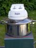
 Presto Poplite Wiring Problem
|
|
| CharcoalRoaster |
Posted on 11/17/2018 2:25 PM
|
 1 1/2 Pounder  Posts: 640 Joined: April 13, 2012 |
Trying to finish up this build and ran into another issue -- this time with getting the wiring straight. I am following the diagram found here https://www.engad...e-roaster/ And using this transformer https://www.amazo...&psc=1 After separating the fan and heater circuits I wired the heating coil to a single pole switch with no issues. Heat cranks on no problem. My first wiring attempt of the fan to a dimmer tripped my breaker because I think I had the transformer switched backwards. I had the 120v side of the transformer wired to the fan. Once I figured that one out I turned it around and rewired it so that the 24v leads were connected to the fan. It did certainly crank up the fan speed to where it could loft some greens before it tripped the breaker. However, once I rewired it and plugged it back into the outlet the dimmer would turn the fan on but (1) it was the same speed as original to the unit and (2) no variable control with the dimmer. I've been looking around for other wiring diagrams that can help me out but no luck. What am I missing with my wiring that would allow power but no dimmer control? |
|
|
|
| JackH |
Posted on 11/17/2018 2:40 PM
|
 Administrator Posts: 1809 Joined: May 10, 2011 |
Make sure that the dimmer is in series with one of the transformer input leads: I swiped this from another popper build. It is a much better schematic/drawing: (Ignore the optional router control) The site - http://popperyii....i-mod.html 
JackH attached the following image:

---Jack
KKTO Roaster. |
|
|
|
| CharcoalRoaster |
Posted on 11/17/2018 3:07 PM
|
|
1 1/2 Pounder Posts: 640 Joined: April 13, 2012 |
Thanks Jack! I followed that schematic and same result. Heat works great on the switch -- no problems there. However, dimmer turns the fan on but no variable control and same speed as came with the unit. Is it possible that when I reversed the transformer wiring with the 110 on the fan side that I blew the transformer? Or the dimmer? and that is what is causing the problem? |
|
|
|
| JackH |
Posted on 11/17/2018 4:20 PM
|
|
Administrator Posts: 1809 Joined: May 10, 2011 |
If your fan is operating at full speed then my guess would be a bad dimmer. Does it have a push on/off? One push of the switch is off and another push activates the dimmer. ---Jack
KKTO Roaster. |
|
|
|
| CharcoalRoaster |
Posted on 11/17/2018 4:34 PM
|
|
1 1/2 Pounder Posts: 640 Joined: April 13, 2012 |
Bummer, yeah it smelled a little funky once I popped the breaker. It's not a push button -- it clicks on turn to engage the fan. |
|
|
|
| renatoa |
Posted on 11/18/2018 12:50 AM
|
|
Administrator Posts: 3104 Joined: September 30, 2016 |
Standard dimmers, i.e. zero cross based, does not like inductive loads as are transformers... or induction motors... We are using here PWM DC dimmers, placed in series with the motor. Their principle is different, they are chopping the rectified sine, or DC, in multiple high frequency pulses, about 500 Hz, with variable duty cycle. Edited by renatoa on 11/18/2018 5:44 AM |
|
|
|
| ChicagoJohn |
Posted on 11/18/2018 5:27 AM
|
 Pounder  Posts: 513 Joined: June 15, 2015 |
Quote renatoa wrote: Standard dimmers, i.e. zero cross based, does not like inductive loads as are transformers... or induction motors... We are using here PWM DC dimmers, placed in series with the motor. There principle is different, they are chopping the rectified sine, or DC, in multiple high frequency pulses, about 500 Hz, with variable duty cycle. Rheostat / coil-based voltage regulators (autotransformers) don't work well with inductive loads. However residential light dimmers of the rotary type are dual-SCR based devices that produce a chopped AC with varying pulse width at constant frequency. I used a common rotary light dimmer from Home Depot on both of the popper builds I did on the 120VAC primary side of the 24VAC transformer with a full-wave bridge rectifying the output to unregulated DD, and they continue to work fine. On the larger air-roaster I did, I used a cheap SCR (triac) to control the 120VAC universal vacuum motor. So many beans; so little time.... |
|
|
|
| renatoa |
Posted on 11/18/2018 5:56 AM
|
|
Administrator Posts: 3104 Joined: September 30, 2016 |
Nobody wrote about autotransformers above, I meant the rectangular component, labelled dimmer, between the mains and 25V transformer. The chopped half sine shape produced by these dimmers isn't appropriate for a transformer input, as the sharp vertical front in the moment of triac firing is generating a lot of harmonics => iron core heat. This kind of controller does a better job, imo... https://www.ebay....mp;_sop=15 ... placed between transformer/bridge and motor. Edited by ChicagoJohn on 11/18/2018 10:43 AM |
|
|
|
| CharcoalRoaster |
Posted on 11/18/2018 6:57 AM
|
|
1 1/2 Pounder Posts: 640 Joined: April 13, 2012 |
So, can I pick up a new dimmer...?  Or do I need to go in a different direction for fan output? |
|
|
|
| ChicagoJohn |
Posted on 11/18/2018 10:45 AM
|
|
Pounder Posts: 513 Joined: June 15, 2015 |
Quote renatoa wrote: Nobody wrote about autotransformers above, I meant the rectangular component, labelled dimmer, between the mains and 25V transformer. The chopped half sine shape produced by these dimmers isn't appropriate for a transformer input, as the sharp vertical front in the moment of triac firing is generating a lot of harmonics => iron core heat. This kind of controller does a better job, imo... https://www.ebay....mp;_sop=15 ... placed between transformer/bridge and motor. In an SCR you don't have a "sharp vertical front" to the wave. What happens is when the voltage reaches a certain point (variable), it cuts out. So in effect, with a dual SCR device like a dimmer switch is, you are changing the RMS voltage of the AC that is input to the transformer primary at the same frequency as line AC. SCR's and true PWM are two different things, but in SCR the width of the normal sine wave rise (+ or -) does vary but the frequency does not change. Again, I used these for a couple years and they work fine. I had no problem with them on either build. Edited by ChicagoJohn on 11/18/2018 10:50 AM So many beans; so little time.... |
|
|
|
| JackH |
Posted on 11/18/2018 2:58 PM
|
|
Administrator Posts: 1809 Joined: May 10, 2011 |
Quote CharcoalRoaster wrote: So, can I pick up a new dimmer...? Or do I need to go in a different direction for fan output? I have also built this popper setup with the Poppery II. The dimmer in the build article will work fine. $6 at Home Depot. ---Jack
KKTO Roaster. |
|
|
|
| renatoa |
Posted on 11/19/2018 2:07 AM
|
|
Administrator Posts: 3104 Joined: September 30, 2016 |
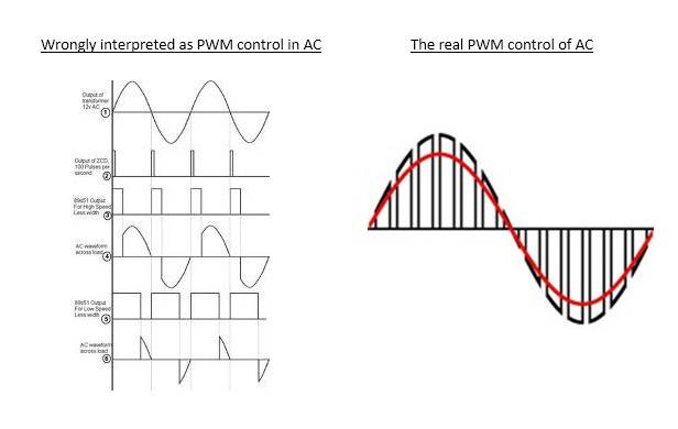
"In an SCR you don't have a "sharp vertical front" to the wave." Dare to disagree... This is how a SCR works, see attached, the left side. "when the voltage reaches a certain point (variable), it cuts out" Actually, is the reverse, the triac is fired when the sine wave reach a certain point in time (time, not voltage). Thus the name: Phase Angle Control. That's because a triac, once fired, can't be cut until the sine cross the zero line. The final result is indeed, a variation of RMS of AC voltage, but the sine waveform change is not good for inductive loads. The frequency does not change for PWM choppers too, what is changed is the duty cycle, see the right side picture. ...
renatoa attached the following image:
Edited by renatoa on 11/19/2018 2:28 AM |
|
|
|

| Jump to Forum: |
Powered by PHP-Fusion Copyright © 2024 PHP-Fusion Inc
Released as free software without warranties under GNU Affero GPL v3
Designed with ♥ by NetriXHosted by skpacman