
Login

Shoutbox
You must login to post a message.
renatoa
07/26/2024 3:49 PM
Bill grubbe and Jk, 
allenb
07/26/2024 5:15 AM
Spiderkw Welcome to HRO!

renatoa
07/24/2024 8:31 AM
ramiroflores and John123,

 ?
?
?renatoa
07/21/2024 1:18 AM
 , Luislobo
renatoa
07/19/2024 11:28 AM
Koepea,
Forum Threads
Newest Threads
Skywalker roaster modsBackground Roast Iss...
Hello from Arkansas
TC4ESP
Green coffee reviews
Hottest Threads
| Skywalker roaster... | [375] |
| TC4ESP | [115] |
| War on Farmers by... | [47] |
| Adventures in flu... | [26] |
| Hello! (soon) Roa... | [17] |
In Memory Of Ginny

Donations
Latest Donations
dmccallum - 10.00
JackH - 25.00
snwcmpr - 10.00
Anonymous - 2.00
Anonymous - 5.00
dmccallum - 10.00
JackH - 25.00
snwcmpr - 10.00
Anonymous - 2.00
Anonymous - 5.00
Users Online
Guests Online: 4
Members Online: 0
Total Members: 8,393
Newest Member: Bill grubbe
Members Online: 0
Total Members: 8,393
Newest Member: Bill grubbe
View Thread
Who is here? 1 guest(s)
 Transparent Fluid Bed Design
|
|
| CK |
Posted on 12/23/2018 9:14 PM
|
|
1/2 Pounder  Posts: 252 Joined: December 07, 2018 |
Thanks greencardigan, There are 2 thermocouples in this machine... 1 in the hot air supply tube below the RC, and 1 in the top of the machine. The top connection is a custom soldered USB male/female connector to the thermocouple wires, allowing the top to detach. These 2 sensors interface with a Yoctopuce thermocouple module, and Coffee Roaster Pro android software. The 3 displays are power meters... They allow me to measure power consumption of the machine's 3 separate circuits, and at the same time avoid tripping circuit breakers. They aren't needed, but have helped learn the system. A few days ago I insulated the heater body. After roasting 4 batches, the power meters showed the power savings when compared to the original roaster without insulation. Edited by CK on 12/28/2018 1:20 PM |
|
|
|
| CK |
Posted on 12/24/2018 12:04 AM
|
|
1/2 Pounder Posts: 252 Joined: December 07, 2018 |
Here are some numbers from the last day of roasting with the machine. Roast #1 used the most power because the machine was not preheated before beginning. The following 3 roasts, after machine preheating, all had very similar w/hr usage despite having different bean charges.
CK attached the following image:

|
|
|
|
| CK |
Posted on 12/24/2018 12:08 PM
|
|
1/2 Pounder Posts: 252 Joined: December 07, 2018 |
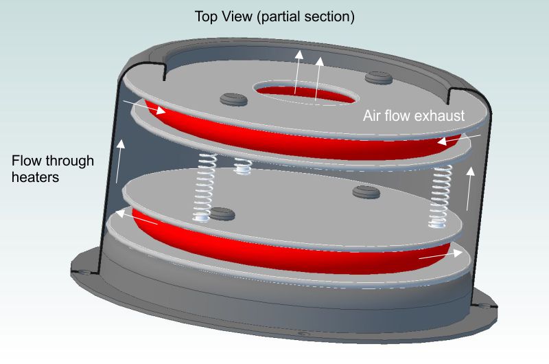
Air flow mapping the insulated transparent roaster.
CK attached the following image:

|
|
|
|
| CK |
Posted on 12/28/2018 6:35 PM
|
|
1/2 Pounder Posts: 252 Joined: December 07, 2018 |
Here is a view of the heater housing used from a Twobiu hot air popper. Inside is the large coil (heater 1) of the Twobiu popper with the small coil removed. Heater 2 is from a Popflix popper. It is sandwiched on top of heater 1. The Popflix mica plates were trimmed with a dremel to fit this housing. Airflow comes up the center of the bottom heater - flows outwards towards the steel case passing heater coil 1 - then flows upwards along the wall of the case and inwards passing the Popflix heat coil 2 - finally exiting out the top center into the delivery pipe.
CK attached the following image:

|
|
|
|
| CK |
Posted on 12/31/2018 8:12 PM
|
|
1/2 Pounder Posts: 252 Joined: December 07, 2018 |
A video of how the roast chamber and chaff collection chamber can be washed. |
|
|
|
| renatoa |
Posted on 01/01/2019 2:13 AM
|
|
Administrator Posts: 3104 Joined: September 30, 2016 |
How often they need washing ? |
|
|
|
| CK |
Posted on 01/01/2019 8:36 AM
|
|
1/2 Pounder Posts: 252 Joined: December 07, 2018 |
Quote This was after about 6 roasts. Normally after a day of roasting I store the machine in my office for a few weeks. I prefer to clean the containers before storing them, otherwise there can be a smell of residuals from chaff and oils. |
|
|
|
| renatoa |
Posted on 01/01/2019 10:46 AM
|
|
Administrator Posts: 3104 Joined: September 30, 2016 |
Similar to the glass of the turbo oven lid. Asked because I didn't seen so far nobody mentioning this detail for their FB or TO glass maintenance. Only the Gene guys sometimes. Also curious how the drums roasters aren't cleaned for years, and not accumulating tons of residues... |
|
|
|
| CK |
Posted on 01/05/2019 9:33 PM
|
|
1/2 Pounder Posts: 252 Joined: December 07, 2018 |
In case anyone else is building a roaster that has 3D printed parts on the machine, you may want to install threaded inserts for a stronger connection. This is a simple and effective technique of how to do it. Before these inserts, I used generic wood screws to hold parts together. That often caused the plastic to split when tightening, and the threads stripped easily. These cheap inserts are much better for making strong connections on your model. The custom tool I'm using is a 20mm M3 hex screw with the leftover silicone feet from a hot air popper. These insulate my fingers from the hot screw. I put nuts on the screw to space out the silicone feet so they cover nearly the whole 20mm length. Just the tip of the screw is available for putting your threaded insert on as seen in the video. When you set the insert to the plastic, the silicone feet act as a natural level for the install. |
|
|
|
| Brandon |
Posted on 01/07/2019 8:17 PM
|
 Newbie  Posts: 47 Joined: July 30, 2013 |
I really like this design and execution. Well done! |
|
|
|
| CK |
Posted on 01/07/2019 9:05 PM
|
|
1/2 Pounder Posts: 252 Joined: December 07, 2018 |
Thanks Brandon, I'll be posting a parts list soon in case anyone would like to do something similar. |
|
|
|
| eltakeiteasy |
Posted on 01/08/2019 7:06 PM
|
|
Newbie Posts: 9 Joined: January 07, 2019 |
This is the coolest roaster I have ever seen! I have been searching to make my own and this is absolutely amazing! Hat off to you sir! |
|
|
|
| jessep |
Posted on 01/08/2019 9:35 PM
|
|
Newbie Posts: 33 Joined: January 05, 2019 |
Quote CK wrote: Thanks Brandon, I'll be posting a parts list soon in case anyone would like to do something similar. yes please! |
|
|
|
| CK |
Posted on 01/09/2019 1:02 PM
|
|
1/2 Pounder Posts: 252 Joined: December 07, 2018 |
Here's the completed transparent roaster with insulation and aesthetic covers over the insulated heater. The top in this image is removed for loading/unloading beans or chaff.
CK attached the following image:

|
|
|
|
| eltakeiteasy |
Posted on 01/09/2019 2:31 PM
|
|
Newbie Posts: 9 Joined: January 07, 2019 |
Quote CK wrote: Here's the completed transparent roaster with insulation and aesthetic covers over the insulated heater. The top in this image is removed for loading/unloading beans or chaff. Looks great! |
|
|
|
| a1970gto |
Posted on 01/10/2019 5:13 PM
|
|
Newbie Posts: 34 Joined: October 31, 2018 |
That's pretty awesome! I'm a far cry from that. |
|
|
|
| CK |
Posted on 01/10/2019 7:36 PM
|
|
1/2 Pounder Posts: 252 Joined: December 07, 2018 |
Thank you everyone for the positive feedback. Some of you have been curious about the build, so here is a material list as promised. These items are used to create the transparent roaster as seen today. (I hope everything is accounted for.) Many more materials and products were used and discarded during R&D/trial and error over the course of a year... That is part of the enjoyment of this rabbit hole we all go down when making custom roasters.
CK attached the following image:

Edited by CK on 02/24/2019 11:05 PM |
|
|
|
| Estrangedinbaja |
Posted on 01/10/2019 8:15 PM
|
|
Newbie Posts: 2 Joined: January 10, 2019 |
Quote CK wrote: Thank you everyone for the positive feedback. Some of you have been curious about the build, so here is a material list as promised. These items are used to create the transparent roaster as seen today. (I hope everything is accounted for.) Many more materials and products were used and discarded during R&D/trial and error over the course of a year... That is part of the enjoyment of this rabbit hole we all go down when making custom roasters. Hey CK, Any idea of a general ballpark of what this machine cost to build? |
|
|
|
| CK |
Posted on 01/10/2019 9:59 PM
|
|
1/2 Pounder Posts: 252 Joined: December 07, 2018 |
Quick answer; more than planned... But it's a fun hobby. General ball park looking at the list... my cost of items (not including failed parts and ideas along the way), probably about $900-$1000. Much could be sourced cheaper from overseas if a person doesn't mind waiting 6-8 weeks for shipping... I don't have the time for that, so my costs were higher to get product fast. Also, I would guess a few hundred hours of design, CAD, reading reviews, learning about products, and shopping for parts. Edited by CK on 02/24/2019 11:07 PM |
|
|
|
| CK |
Posted on 01/10/2019 10:40 PM
|
|
1/2 Pounder Posts: 252 Joined: December 07, 2018 |
Here's an image to show the scale of the small 2 amp - 240w motor used in this build. It's a good fit for this design and the 4th motor I tested. It came from a Bissell corded stick vacuum. https://canada.bi...030c#specs Previously I tried; 1. 50mm EDF @ DC 14.8V 250 watts for RC planes - fun and powerful with lots of flow under no pressure, but it stalls with static pressure from heater resistance, ducting, and bean mass, no good 2. 10A 1200 watt full size vacuum motor - too heavy and loud, much vibration, too dirty - from a used vacuum 3. 5A 600 watt corded stick vac motor - great sized unit to be used in version 2 with Arduino/TC4 setup.
CK attached the following image:

Edited by CK on 01/18/2019 1:23 PM |
|
|
|
| renatoa |
Posted on 01/11/2019 2:25 AM
|
|
Administrator Posts: 3104 Joined: September 30, 2016 |
Yep, and this can be found as spares in the $20 ballpark, for a lot of vac brands, posted somewhere in the past a brands/codes list of similar items... LE: AEG Ardo Bosch Brandt Candy Electrolux Hoover LG Moulinex Nilfisc Philips Rowenta Samsung Siemens Cross Reference: EAU61004901 VCC264E02 VC9205FS4 VK8914NHCQ |
|
|
|
| CK |
Posted on 01/14/2019 10:46 PM
|
|
1/2 Pounder Posts: 252 Joined: December 07, 2018 |
This is a CAD bottom and top section view of the heater and how it was made. These show the intake and exhaust air flow pattern through the custom heat coils.
CK attached the following images:

|
|
|
|
| Linnaeus |
Posted on 01/18/2019 8:45 AM
|
|
Newbie Posts: 49 Joined: September 12, 2017 |
Hey CK, Really like your build. Very original configuration. I used a 3d printer for mine as well, but only to print molds. ( https://forum.homeroasters.org/forum/viewthread.php?thread_id=5442 ) I'm really intrigued by the 3d printed couplings. How is it that they do not melt under the heat? Specifically the coupling at the top of your roast chamber. |
|
|
|
| CK |
Posted on 01/18/2019 1:01 PM
|
|
1/2 Pounder Posts: 252 Joined: December 07, 2018 |
Quote Linnaeus wrote: I'm really intrigued by the 3d printed couplings. How is it that they do not melt under the heat? Specifically the coupling at the top of your roast chamber. Thanks Linnaeus. The couplings were made using high temperature food grade PLA from 3DK Berlin in Germany (3DK TOP). It needs to be annealed in an oven at 110C after printing, which causes it to shrink 3-4% on the horizontal plane, and a little expansion on the vertical depending on the part geometry. After that it's loadable to about 230C with no issues at all. My exhaust temperature never gets above 220C, so all works just fine. Edited by CK on 01/18/2019 2:45 PM |
|
|
|
| CK |
Posted on 01/18/2019 1:28 PM
|
|
1/2 Pounder Posts: 252 Joined: December 07, 2018 |
As a clarification, this is the blower/motor in my build. https://canada.bi...030c#specs Edited by CK on 02/24/2019 11:10 PM |
|
|
|

| Jump to Forum: |
Powered by PHP-Fusion Copyright © 2024 PHP-Fusion Inc
Released as free software without warranties under GNU Affero GPL v3
Designed with ♥ by NetriXHosted by skpacman