
Login

Shoutbox
You must login to post a message.
renatoa
07/26/2024 3:49 PM
Bill grubbe and Jk, 
allenb
07/26/2024 5:15 AM
Spiderkw Welcome to HRO!

renatoa
07/24/2024 8:31 AM
ramiroflores and John123,

 ?
?
?renatoa
07/21/2024 1:18 AM
 , Luislobo
renatoa
07/19/2024 11:28 AM
Koepea,
Forum Threads
Newest Threads
Skywalker roaster modsBackground Roast Iss...
Hello from Arkansas
TC4ESP
Green coffee reviews
Hottest Threads
| Skywalker roaster... | [375] |
| TC4ESP | [115] |
| War on Farmers by... | [47] |
| Adventures in flu... | [26] |
| Hello! (soon) Roa... | [17] |
In Memory Of Ginny

Donations
Latest Donations
dmccallum - 10.00
JackH - 25.00
snwcmpr - 10.00
Anonymous - 2.00
Anonymous - 5.00
dmccallum - 10.00
JackH - 25.00
snwcmpr - 10.00
Anonymous - 2.00
Anonymous - 5.00
Users Online
Guests Online: 1
Members Online: 0
Total Members: 8,393
Newest Member: Bill grubbe
Members Online: 0
Total Members: 8,393
Newest Member: Bill grubbe
View Thread
Who is here? 1 guest(s)
 Transparent Fluid Bed Design
|
|
| CK |
Posted on 03/27/2019 4:01 PM
|
|
1/2 Pounder  Posts: 252 Joined: December 07, 2018 |
Quote RobS wrote: Did you mount the motor like it was in the vacuum front ring and the rubber rectangle on the back? Yes, both end mounts were printed according to the original vacuum specs. |
|
|
|
| greenthumb |
Posted on 03/29/2019 5:08 PM
|
|
Newbie  Posts: 4 Joined: March 29, 2019 |
Awesome build! I was wondering where you sourced the copper bean cone? You mentioned that it was off the shelf and just wondering if you found it in a hardware store or line. Thanks! |
|
|
|
| CK |
Posted on 03/29/2019 7:19 PM
|
|
1/2 Pounder Posts: 252 Joined: December 07, 2018 |
Thanks Greenthumb. Quote The copper cone is an off the shelf 2" to 3/4" pipe reducer fitting bought here; https://www.amazo...&psc=1 It was cut, filed and then bonded to the SS cone. The image on Amazon isn't representative of the actual part... it is a cone shaped reducer fitting. Real copper, and heavy duty. |
|
|
|
| renatoa |
Posted on 03/30/2019 2:30 AM
|
|
Administrator Posts: 3104 Joined: September 30, 2016 |
This is a real 2 to 3/4 reducer image  https://www.olymp...ng-reducer
renatoa attached the following image:

Edited by renatoa on 04/01/2019 1:57 AM |
|
|
|
| CK |
Posted on 03/30/2019 7:10 AM
|
|
1/2 Pounder Posts: 252 Joined: December 07, 2018 |
Thanks Renatoa, that link is a correct representation image for what the reducer looks like... |
|
|
|
| greenthumb |
Posted on 03/31/2019 10:46 PM
|
|
Newbie Posts: 4 Joined: March 29, 2019 |
Appreciate the help! Might have to visit the supplier in Port Angles for other supplies. |
|
|
|
| CK |
Posted on 04/18/2019 11:23 PM
|
|
1/2 Pounder Posts: 252 Joined: December 07, 2018 |
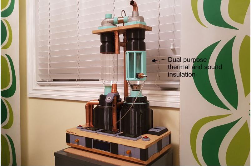
Here's an image of the current iteration of the transparent roaster. (TC4, ZCD, Arduino UNO) The PID has been dialed in relatively well, and the machine now runs automated alarm files for full auto roasting if desired. Analog controls are also functional for manual roasting. From clicking ON in Artisan Roaster Scope, it auto charges, roasts to a specific temperature/time profile, drops/cools, then shuts off when the beans fall below a preset temperature. The RC now has dual purpose insulation installed for easier handling post roast and for quieting the bean pinging on the thin glass. A video will be posted soon. Not sure why, but the image isn't loading as usual? Screenshot loads with image data, but not the image itself... I'll try a screenshot of the roaster.
CK attached the following images:

Edited by CK on 04/19/2019 9:18 AM |
|
|
|
| CK |
Posted on 04/18/2019 11:32 PM
|
|
1/2 Pounder Posts: 252 Joined: December 07, 2018 |
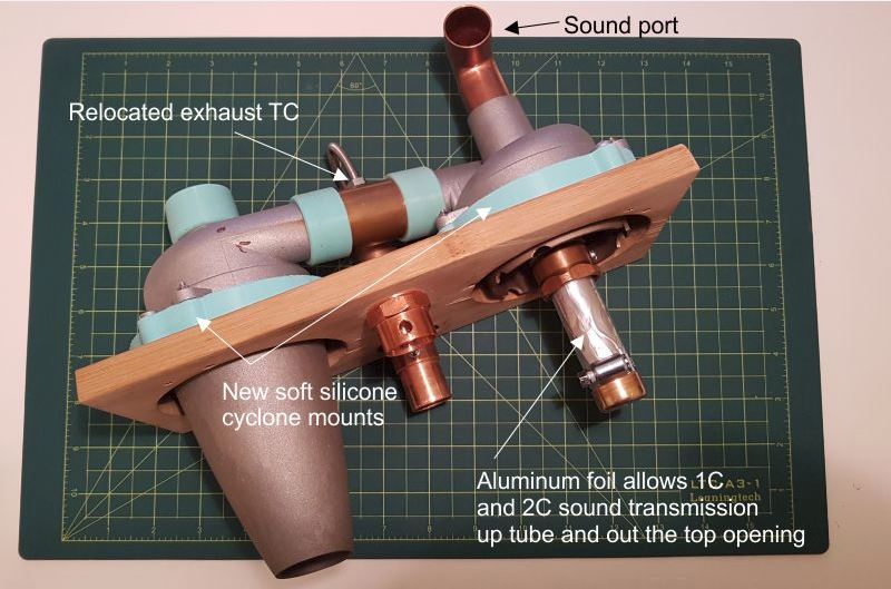
Here's another image. It is of the new sound tube feature of this roaster. It is a custom drilled copper tube with a layer of aluminum foil covering the holes. The thin foil allows for sound to be transmitted up the pipe and out the open-ended elbow fitting towards the user. With this modification, it is now possible to hear 1C and 2C for better roast logging. This post isn't showing the uploads either...
CK attached the following image:
Edited by CK on 04/19/2019 9:19 AM |
|
|
|
| JitterzZ |
Posted on 04/18/2019 11:54 PM
|
 1/4 Pounder  Posts: 151 Joined: October 08, 2018 |
Same happens to me. Try shrinking the image to 800 x 800. By the way, very clever idea to hear the cracks 
Edited by JitterzZ on 04/19/2019 12:10 AM |
|
|
|
| JackH |
Posted on 04/19/2019 2:34 AM
|
 Administrator Posts: 1809 Joined: May 10, 2011 |
It seems to work for me. File names often cause problems. Linux based so try to avoid spaces and special characters. Also do not use the preview feature, it does not work with images and you will have to re-load them again.
JackH attached the following images:


Edited by JackH on 04/19/2019 2:45 AM ---Jack
KKTO Roaster. |
|
|
|
| CK |
Posted on 04/19/2019 9:21 AM
|
|
1/2 Pounder Posts: 252 Joined: December 07, 2018 |
Thanks for the suggestions. The images were identical to my previous uploads so I'm not sure why they won't take this time. Screenshots worked fine. |
|
|
|
| CK |
Posted on 04/26/2019 10:25 PM
|
|
1/2 Pounder Posts: 252 Joined: December 07, 2018 |
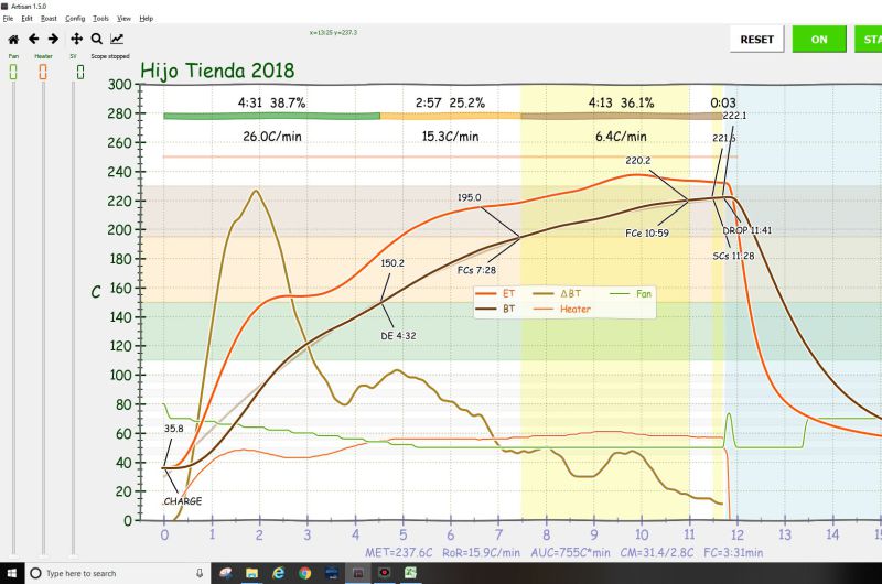
Roasted some Peru naturals today using the Artisan, Arduino UNO, TC4 setup. Here's a screenshot of the way it went. This was fully automated from the click of "ON"... charge, registering temperature markings, fan and heater, and drop. An alarm file was built to match the background profile. Still fine tuning the system PID and steps for the fan... These aren't the phase percentages many people use, but I'm experimenting with the naturals for development and end temperatures now. Tastes good!
CK attached the following image:
|
|
|
|
| CK |
Posted on 04/30/2019 12:22 PM
|
|
1/2 Pounder Posts: 252 Joined: December 07, 2018 |
A video showing bean agitation speed on the current setup. - 300-gram charge - ran at 50% and 100% |
|
|
|
| CK |
Posted on 05/07/2019 7:35 PM
|
|
1/2 Pounder Posts: 252 Joined: December 07, 2018 |
Here's an accelerated video of the actual roast from the screen-shot above. |
|
|
|
| greenthumb |
Posted on 05/12/2019 12:50 PM
|
|
Newbie Posts: 4 Joined: March 29, 2019 |
CK, I was wondering how the roasted beans are removed with your new modifications since it appears that the bean cone is placed within the tapper end of the glass cylinder vice the straighter more narrow section. |
|
|
|
| CK |
Posted on 05/12/2019 2:20 PM
|
|
1/2 Pounder Posts: 252 Joined: December 07, 2018 |
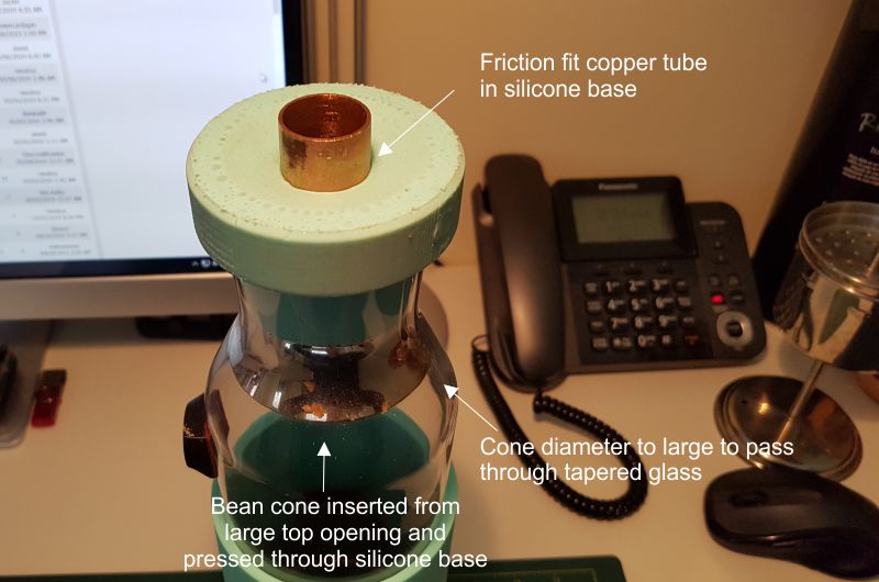
Quote greenthumb wrote: CK, I was wondering how the roasted beans are removed with your new modifications since it appears that the bean cone is placed within the tapper end of the glass cylinder vice the straighter more narrow section. Bean removal is the same as shown in the video on page 1. The whole carafe comes off to dump the beans and the cone stays friction fixed (via the copper tube) in its silicone base. The new metal cone is assembled by inserting from the top of the carafe and into the silicone base of the carafe. The cone is slightly too big to pass through the tapered bottom portion of glass so it all fits snug. |
|
|
|
| CK |
Posted on 05/12/2019 2:47 PM
|
|
1/2 Pounder Posts: 252 Joined: December 07, 2018 |
Images explain better.
CK attached the following image:
|
|
|
|
| CK |
Posted on 05/20/2019 3:34 PM
|
|
1/2 Pounder Posts: 252 Joined: December 07, 2018 |
Here's a video of how the sound tube was constructed and assembled. Before this modification sounds from 1C and 2C weren't audible on the roaster due to blower noise. Although the sounds of 1C and 2C are still slightly low, this unique feature allows roasters to hear the audible cracks for better data logging. (I may remove some layers of aluminum foil to allow better sound transmission. This version has multiple layers.) |
|
|
|
| treyd |
Posted on 06/05/2019 1:35 PM
|
 Newbie Posts: 3 Joined: June 28, 2018 |
This is a really cool roaster build. Very nice design and use of materials. After seeing this post, I think I'll refrain from posting my own, now very humbled efforts. ;-) I would like to ask why you chose to use the Smooth-sil 960 vs 950 or 940? Was it for the rigidity, the cure time or maybe the color? Also, how critical to the curing process is a vacuum chamber? I have a 3D printer also and have used it for a number of roaster parts already. Now that I know of high temp casting silicone I really want to print some custom molds and use it in my roaster build for an RC mount and for mating other components. You mentioned having a 600W vac motor you plan to use for a v2 build. Have you noticed, for a given airflow, if the 600W motor is quieter than the 250W motor? Thanks again for sharing your build and all the related details. |
|
|
|
| CK |
Posted on 06/05/2019 9:46 PM
|
|
1/2 Pounder Posts: 252 Joined: December 07, 2018 |
Quote treyd wrote: I would like to ask why you chose to use the Smooth-sil 960 vs 950 or 940? Was it for the rigidity, the cure time or maybe the color? Also, how critical to the curing process is a vacuum chamber? Thanks Treyd. Smooth-Sil 960 has the highest Shore rating (60A I believe) so it is harder when cured. I didn't use a vacuum chamber at first, and the parts turned out okay. A vac chamber isn't needed for curing, only degassing. Without degassing there will be bubbles entrapped on the top of the curing part that may affect quality and looks. If you look at the bottom of the RC base in the above image you can see the bubbles there. They're still fully functional, and the defects are hidden so I didn't cast them again. |
|
|
|
| CK |
Posted on 06/05/2019 9:57 PM
|
|
1/2 Pounder Posts: 252 Joined: December 07, 2018 |
Quote treyd wrote: You mentioned having a 600W vac motor you plan to use for a v2 build. Have you noticed, for a given airflow, if the 600W motor is quieter than the 250W motor? V2 is a completely new build I'm working on. Different look and flow dynamics. It is louder using the 600W motor, but I think that is from the housing design being boxy. Some more R&D and insulation will lower the decibels on the new machine, hopefully to the sound level of the transparent roaster. The 250W blower runs at 70% at the start of a roast and down to 40% at the end of the roast with a low sound level of about 62-65 decibels on my sound meter. |
|
|
|
| salperta |
Posted on 06/16/2019 7:16 PM
|
|
Newbie Posts: 10 Joined: June 16, 2019 |
This is totally amazing engineering! I am really inspired. I do have a question--would you mind sharing how you housed the vacuum motor, and got it to blow air? Did you merely house it so that the suctioned air which blows over the motor to cool it is then funneled in order to create higher pressure, or did you remove that steel sheath over the fans and divert the air from there? Or maybe your motor simply reverses? Thanks so much CK, this is really incredible work, and beautiful to boot. |
|
|
|
| CK |
Posted on 06/17/2019 9:46 AM
|
|
1/2 Pounder Posts: 252 Joined: December 07, 2018 |
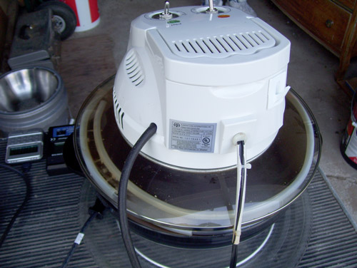
Quote salperta wrote: I do have a question--would you mind sharing how you housed the vacuum motor, and got it to blow air? Thank you Salperta. My motor housing is simply a "clam-shell type" design that entraps the motor. The top half engages the motor top mount with its rubber cushion, and bottom half engages the bottom mount and its rubber cushion. The parts have an intermeshed lip and groove setup for improved air tightness at the seam. The important thing is to keep it airtight from the inlet to the outlet side. Then simply decide how you'd like to direct your airflow to the heater section.
CK attached the following image:

|
|
|
|
| CK |
Posted on 06/17/2019 9:55 AM
|
|
1/2 Pounder Posts: 252 Joined: December 07, 2018 |
Quote salperta wrote: Did you merely house it so that the suctioned air which blows over the motor to cool it is then funneled in order to create higher pressure, or did you remove that steel sheath over the fans and divert the air from there? Keep your motor stock... it will work just fine. After you test your housing and ensure the system works properly, and you have it just how you want it to look, seal the top (intake) and bottom (exhaust) seams with silicone for better pressurization of the system. |
|
|
|
| BrewBoy |
Posted on 08/15/2019 10:05 AM
|
|
Newbie Posts: 2 Joined: August 15, 2019 |
Just joined the forum due to this thread. Amazing ingenuity! Thank you CK for all of your generous contributions thus far! Very much looking forward to seeing you V2 design, may I ask how it's coming along? |
|
|
|

| Jump to Forum: |
Powered by PHP-Fusion Copyright © 2024 PHP-Fusion Inc
Released as free software without warranties under GNU Affero GPL v3
Designed with ♥ by NetriXHosted by skpacman