
Login

Shoutbox
You must login to post a message.
renatoa
07/26/2024 3:49 PM
Bill grubbe and Jk, 
allenb
07/26/2024 5:15 AM
Spiderkw Welcome to HRO!

renatoa
07/24/2024 8:31 AM
ramiroflores and John123,

 ?
?
?renatoa
07/21/2024 1:18 AM
 , Luislobo
renatoa
07/19/2024 11:28 AM
Koepea,
Forum Threads
Newest Threads
Skywalker roaster modsBackground Roast Iss...
Hello from Arkansas
TC4ESP
Green coffee reviews
Hottest Threads
| Skywalker roaster... | [375] |
| TC4ESP | [115] |
| War on Farmers by... | [47] |
| Adventures in flu... | [26] |
| Hello! (soon) Roa... | [17] |
In Memory Of Ginny

Donations
Latest Donations
dmccallum - 10.00
JackH - 25.00
snwcmpr - 10.00
Anonymous - 2.00
Anonymous - 5.00
dmccallum - 10.00
JackH - 25.00
snwcmpr - 10.00
Anonymous - 2.00
Anonymous - 5.00
Users Online
Guests Online: 5
Members Online: 0
Total Members: 8,393
Newest Member: Bill grubbe
Members Online: 0
Total Members: 8,393
Newest Member: Bill grubbe
View Thread
Who is here? 1 guest(s)
 Transparent Fluid Bed Design
|
|
| CK |
Posted on 09/21/2020 12:23 PM
|
|
1/2 Pounder  Posts: 252 Joined: December 07, 2018 |
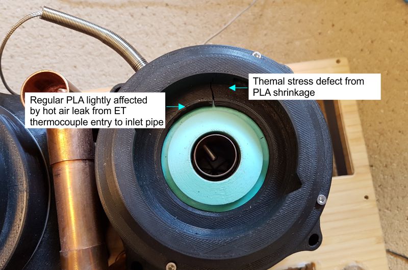
When reconfiguring the build a defect was found on the heater lid part. It still functions well to hold the RC... a high temperature PLA reprint may be made for a fix.
CK attached the following image:
|
|
|
|
| floptronica |
Posted on 10/07/2020 6:41 AM
|
|
Newbie  Posts: 2 Joined: October 07, 2020 |
That's a very nice rig you made. I had no idea about the high temp PLA and the gizmo to hear 1st crack better is a new idea to me. So much nicer than holding my ear next to the roast chamber. One Idea i might contribute to your build is to roll your own heating elements. The ones that come with poppers are made with the cheapest possible material, and just don't last too long. Ive been using nichrome 80 in 20 gauge, and an element lasts over a year. Use a knitting needle to roll it. Just get one in the mm diameter of your old coil. |
|
|
|
| CK |
Posted on 10/08/2020 1:47 PM
|
|
1/2 Pounder Posts: 252 Joined: December 07, 2018 |
Thanks for the tips on rolling custom coils and wire choice. That may come in handy in the future if there is need to do repairs. The original coils are still going strong with more than 2 years roasting and testing on them... perhaps because I don't run them maxed out. (They only run at about 50-60% of their potential.) I've simplified the FC sound feature by removing the copper piping, and putting foil directly over the 1" top opening. It's clamped in place with a band clamp over a silicone gasket, keeping the foil relatively flat and stretched tight. The function works just as well as the complicated copper pipe design. |
|
|
|
| TooL |
Posted on 02/07/2021 6:28 AM
|
|
Newbie Posts: 2 Joined: January 17, 2019 |
Hey there, I've been having a peruse through this thread cause this is a really neat design. Have I missed a part list or have you not released one? Just curious as I'm thinking of making a roaster myself and I am curious about how much this kind of setup would cost  One thing I'm interested in is how it's all powered, do you have a big psu of some sort or is everything just individually plugged into an extension bar or something? Cheers either way as it's been cool to see the idea and progression |
|
|
|
| CK |
Posted on 02/07/2021 11:26 PM
|
|
1/2 Pounder Posts: 252 Joined: December 07, 2018 |
You can refer to posts 21, 23, 42, and 44 for the information. Each 120v power inlet is pulled from a different circuit in the home. |
|
|
|
| TooL |
Posted on 02/12/2021 2:14 PM
|
|
Newbie Posts: 2 Joined: January 17, 2019 |
Oh awesome I feel a bit silly. So you power it with a bunch of plugs, makes a lot of sense haha. Cheers, totally should have seen that |
|
|
|
| iPa |
Posted on 01/20/2022 4:54 AM
|
|
Newbie Posts: 44 Joined: December 22, 2021 |
Quote CK wrote: Here's a screenshot of a recent ET PID roast from a couple of weeks ago. The PID follows the profile easily and consistently now. Using the Artisan profile designer, a person can adjust for total time, end temperature desired, and thus affect phase percentages as well. Simply save the generic profile as a template to be used for any bean type you like with that curve and flavor. What is the advantage of ET PID vs BT PID ? I think I am missing something, ET is following the background curve, so how is it possible to define(predict) BT temperature ? |
|
|
|
| renatoa |
Posted on 01/20/2022 6:16 AM
|
|
Administrator Posts: 3104 Joined: September 30, 2016 |
Thermodynamic laws: https://homeroast...post_73960 Getting a reliable BT is a lottery in some machines. In such cases has more sense to drive the roast based on ET, and some knowledge. There are $$$$ FB roasting machines not even featuring a BT sensor, and used by pros for sampling. |
|
|
|
| CK |
Posted on 01/20/2022 11:26 AM
|
|
1/2 Pounder Posts: 252 Joined: December 07, 2018 |
Quote iPa wrote: What is the advantage of ET PID vs BT PID ? I think I am missing something, ET is following the background curve, so how is it possible to define(predict) BT temperature ? ET PID is very easy to achieve. When you have the proper PID settings for your machine, the resulting heat profile is always smooth and consistent. The BT will naturally follow a smooth profile based on the thermal characteristics of your machine... there is no radically fluctuating BT during the roast. (This can also be achieved with a heater power profile, no PID involved, just smooth power increases to create the desired time and temperature curve you want as Renato often says. You see an example of power curve roast control in post#1 and #9 here https://homeroast...post_74801) The key is practice, practice, practice to learn how your machine transfers heat to the beans... this will vary depending on charge weight, so it's easier to learn using a constant charge weight. |
|
|
|
| renatoa |
Posted on 01/20/2022 1:39 PM
|
|
Administrator Posts: 3104 Joined: September 30, 2016 |
An alternate approach is to use power profiles instead temperature profiles, for machines where the relation power ~ heat is mostly linear. Thus no more need for PID settings/tuning. It's a simple mod for TC4, but unfortunately Artisan lacks support for power profiles. |
|
|
|
| rk27 |
Posted on 07/07/2022 1:58 PM
|
 Newbie Posts: 12 Joined: July 27, 2020 |
Quote CK wrote: Quote Does the RC cover, taken from a second cyclone, requires a cut job, or you succeeded to dismount the cyclone in the two component parts ? The aluminum cyclone is one piece and needed cutting. Here's an image of the underside of the RC and CC lid with the solution that worked in this setup. Hey CK, once again great build, thanks a lot for sharing all the information. Following your posts I also made a roaster out from Ikea carafe. Just a quick question, how does the holes in the cyclone actually prevent beans from escaping the RC through the main exhaust hole? |
|
|
|
| CK |
Posted on 07/09/2022 4:55 PM
|
|
1/2 Pounder Posts: 252 Joined: December 07, 2018 |
I'm not sure I understand the question, but here is an image to explain. Please see post #28 for airflow mapping. (images not loading... sorry) |
|
|
|
| CK |
Posted on 07/10/2022 10:02 PM
|
|
1/2 Pounder Posts: 252 Joined: December 07, 2018 |
Quote CK wrote: I'm not sure I understand the question, but here is an image to explain. Please see post #28 for airflow mapping. (images not loading... sorry)
CK attached the following image:

|
|
|
|
| rk27 |
Posted on 07/12/2022 9:33 AM
|
|
Newbie Posts: 12 Joined: July 27, 2020 |
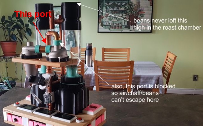
Quote Thanks for the image CK. I meant the port that exits the roasting chamber and goes to the chaff collector. I see now from your image that beans never get that high. Just wondering is there any reason you cut these semi-circular holes in the lid on top of the roasting chamber. Attached the images to better describe what I mean.
rk27 attached the following images:

Edited by rk27 on 07/12/2022 9:47 AM |
|
|
|
| CK |
Posted on 07/13/2022 3:11 PM
|
|
1/2 Pounder Posts: 252 Joined: December 07, 2018 |
Quote Just wondering is there any reason you cut these semi-circular holes in the lid on top of the roasting chamber. Attached the images to better describe what I mean. Those semi-circular holes are from when I drilled the cyclone originally... no function anymore. Originally I had tried to vent the chaff by drilling many 10mm holes all around the cyclone body as seen in the upper image with the red description. That prototype failed, so I just cut the whole cyclone off instead... Everything worked fine after that. |
|
|
|

| Jump to Forum: |
Powered by PHP-Fusion Copyright © 2024 PHP-Fusion Inc
Released as free software without warranties under GNU Affero GPL v3
Designed with ♥ by NetriXHosted by skpacman