
Login

Shoutbox
You must login to post a message.
renatoa
07/26/2024 3:49 PM
Bill grubbe and Jk, 
allenb
07/26/2024 5:15 AM
Spiderkw Welcome to HRO!

renatoa
07/24/2024 8:31 AM
ramiroflores and John123,

 ?
?
?renatoa
07/21/2024 1:18 AM
 , Luislobo
renatoa
07/19/2024 11:28 AM
Koepea,
Forum Threads
Newest Threads
Skywalker roaster modsBackground Roast Iss...
Hello from Arkansas
TC4ESP
Green coffee reviews
Hottest Threads
| Skywalker roaster... | [375] |
| TC4ESP | [115] |
| War on Farmers by... | [47] |
| Adventures in flu... | [26] |
| Hello! (soon) Roa... | [17] |
In Memory Of Ginny

Donations
Latest Donations
dmccallum - 10.00
JackH - 25.00
snwcmpr - 10.00
Anonymous - 2.00
Anonymous - 5.00
dmccallum - 10.00
JackH - 25.00
snwcmpr - 10.00
Anonymous - 2.00
Anonymous - 5.00
Users Online
Guests Online: 11
Members Online: 0
Total Members: 8,393
Newest Member: Bill grubbe
Members Online: 0
Total Members: 8,393
Newest Member: Bill grubbe
View Thread
Who is here? 1 guest(s)
 Transparent Fluid Bed Design
|
|
| a1970gto |
Posted on 01/10/2019 5:13 PM
|
|
Newbie  Posts: 34 Joined: October 31, 2018 |
That's pretty awesome! I'm a far cry from that. |
|
|
|
| CK |
Posted on 01/10/2019 7:36 PM
|
|
1/2 Pounder  Posts: 252 Joined: December 07, 2018 |
Thank you everyone for the positive feedback. Some of you have been curious about the build, so here is a material list as promised. These items are used to create the transparent roaster as seen today. (I hope everything is accounted for.) Many more materials and products were used and discarded during R&D/trial and error over the course of a year... That is part of the enjoyment of this rabbit hole we all go down when making custom roasters.
CK attached the following image:

Edited by CK on 02/24/2019 11:05 PM |
|
|
|
| Estrangedinbaja |
Posted on 01/10/2019 8:15 PM
|
|
Newbie Posts: 2 Joined: January 10, 2019 |
Quote CK wrote: Thank you everyone for the positive feedback. Some of you have been curious about the build, so here is a material list as promised. These items are used to create the transparent roaster as seen today. (I hope everything is accounted for.) Many more materials and products were used and discarded during R&D/trial and error over the course of a year... That is part of the enjoyment of this rabbit hole we all go down when making custom roasters. Hey CK, Any idea of a general ballpark of what this machine cost to build? |
|
|
|
| CK |
Posted on 01/10/2019 9:59 PM
|
|
1/2 Pounder Posts: 252 Joined: December 07, 2018 |
Quick answer; more than planned... But it's a fun hobby. General ball park looking at the list... my cost of items (not including failed parts and ideas along the way), probably about $900-$1000. Much could be sourced cheaper from overseas if a person doesn't mind waiting 6-8 weeks for shipping... I don't have the time for that, so my costs were higher to get product fast. Also, I would guess a few hundred hours of design, CAD, reading reviews, learning about products, and shopping for parts. Edited by CK on 02/24/2019 11:07 PM |
|
|
|
| CK |
Posted on 01/10/2019 10:40 PM
|
|
1/2 Pounder Posts: 252 Joined: December 07, 2018 |
Here's an image to show the scale of the small 2 amp - 240w motor used in this build. It's a good fit for this design and the 4th motor I tested. It came from a Bissell corded stick vacuum. https://canada.bi...030c#specs Previously I tried; 1. 50mm EDF @ DC 14.8V 250 watts for RC planes - fun and powerful with lots of flow under no pressure, but it stalls with static pressure from heater resistance, ducting, and bean mass, no good 2. 10A 1200 watt full size vacuum motor - too heavy and loud, much vibration, too dirty - from a used vacuum 3. 5A 600 watt corded stick vac motor - great sized unit to be used in version 2 with Arduino/TC4 setup.
CK attached the following image:

Edited by CK on 01/18/2019 1:23 PM |
|
|
|
| renatoa |
Posted on 01/11/2019 2:25 AM
|
|
Administrator Posts: 3104 Joined: September 30, 2016 |
Yep, and this can be found as spares in the $20 ballpark, for a lot of vac brands, posted somewhere in the past a brands/codes list of similar items... LE: AEG Ardo Bosch Brandt Candy Electrolux Hoover LG Moulinex Nilfisc Philips Rowenta Samsung Siemens Cross Reference: EAU61004901 VCC264E02 VC9205FS4 VK8914NHCQ |
|
|
|
| CK |
Posted on 01/14/2019 10:46 PM
|
|
1/2 Pounder Posts: 252 Joined: December 07, 2018 |
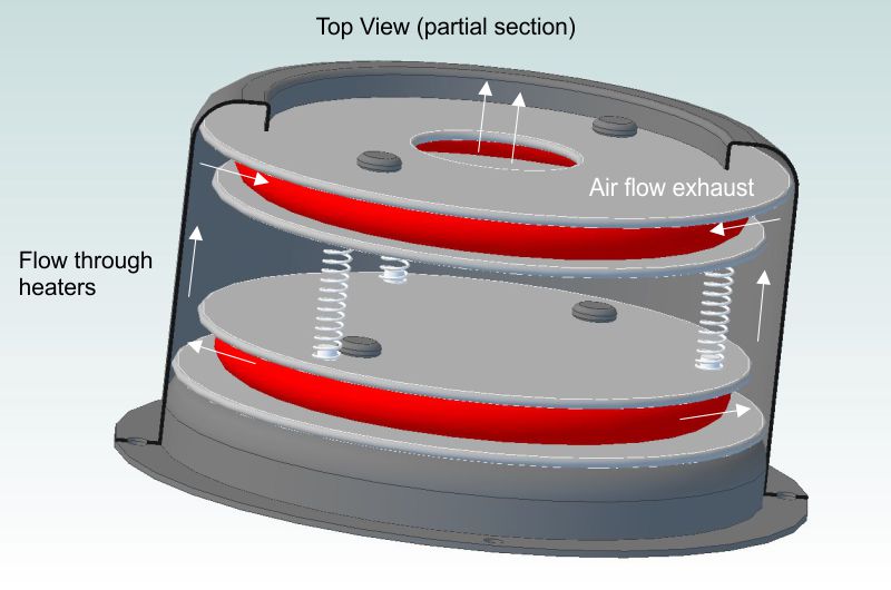
This is a CAD bottom and top section view of the heater and how it was made. These show the intake and exhaust air flow pattern through the custom heat coils.
CK attached the following images:

|
|
|
|
| Linnaeus |
Posted on 01/18/2019 8:45 AM
|
|
Newbie Posts: 49 Joined: September 12, 2017 |
Hey CK, Really like your build. Very original configuration. I used a 3d printer for mine as well, but only to print molds. ( https://forum.homeroasters.org/forum/viewthread.php?thread_id=5442 ) I'm really intrigued by the 3d printed couplings. How is it that they do not melt under the heat? Specifically the coupling at the top of your roast chamber. |
|
|
|
| CK |
Posted on 01/18/2019 1:01 PM
|
|
1/2 Pounder Posts: 252 Joined: December 07, 2018 |
Quote Linnaeus wrote: I'm really intrigued by the 3d printed couplings. How is it that they do not melt under the heat? Specifically the coupling at the top of your roast chamber. Thanks Linnaeus. The couplings were made using high temperature food grade PLA from 3DK Berlin in Germany (3DK TOP). It needs to be annealed in an oven at 110C after printing, which causes it to shrink 3-4% on the horizontal plane, and a little expansion on the vertical depending on the part geometry. After that it's loadable to about 230C with no issues at all. My exhaust temperature never gets above 220C, so all works just fine. Edited by CK on 01/18/2019 2:45 PM |
|
|
|
| CK |
Posted on 01/18/2019 1:28 PM
|
|
1/2 Pounder Posts: 252 Joined: December 07, 2018 |
As a clarification, this is the blower/motor in my build. https://canada.bi...030c#specs Edited by CK on 02/24/2019 11:10 PM |
|
|
|
| pixelsmithy |
Posted on 03/14/2019 10:58 AM
|
|
Newbie Posts: 28 Joined: October 14, 2016 |
Nice build CK. I just wanted to mention that this thread and your YouTube video have been shared in the Facebook Group: "Fluid Bed Coffee Roasters".  |
|
|
|
| CK |
Posted on 03/14/2019 12:28 PM
|
|
1/2 Pounder Posts: 252 Joined: December 07, 2018 |
Thanks pixelsmithy. I've just finished version2 (gutted V1 and put new internals in) and will start posting some of the information soon. The roaster is now automated using Arduino/TC4 and Artisan. |
|
|
|
| homeroaster |
Posted on 03/14/2019 1:23 PM
|
 Newbie Posts: 28 Joined: November 02, 2007 |
An awesome elegant and functional design. Well executed.
*********************
Ed Needham "to absurdity and beyond!" http://www.homero... http://www.facebo...EdNeedham1 ********************* |
|
|
|
| Graeme Lindsay |
Posted on 03/14/2019 4:39 PM
|
|
Newbie Posts: 7 Joined: April 13, 2017 |
Hi CK, What an amazing, well thought-out build...very impressed. I've got a several questions if you don't mind, particularly around PID as dialling in PID for a machine is a frustrating experience for many people. BATCH SIZE I was looking at the power input and roast times that you posted. It looks as though you could have some spare power to potentially push the green bean weight even higher and still roast in a less than 12 minutes. Have you tried larger batch sizes yet or have you found the roast chamber not quite big enough, beans flow not ideal or they shoot out the exhaust? PID SETTINGS AND APPROACH Re the TC4 and Artisan automation I would be really grateful if you could share your PID settings. I know they won't be the exact settings I need as each machine is different, but it would be a good starting point as I'm (along with many others!) finding dialling in Artisan PID settings very frustrating. Been trying standard PID on error as well as the newer PID on input (measurement) feature in Artisan. I'm using an Artisan 6M spouted fluid bed, batches 500 grams to 1.8 kg usually, TC4 hooked up to a Macbook running Artisan (swapped out the heater Fotek VA SSRs for Fotek DA SSRs to enable Artisan control via TC4), still controlling fan manually. What version of Artisan are you using (1.4, 1.5. 1.6.1?) Are you using PID firmware on the TC4 or Artisan software PID? Are you using "PID on error" or "PID on input" (measurement)? What are the P, I and D settings? Are you using the PID mode to follow a "background" or "ramp/soak"? Lookahead period is something I'm still playing around with...been using anywhere from 5-20 seconds...what period have you settled on? Sampling interval? Also, very curious as to your approach to PID tuning...lots of discussion/frustration in these forums and others on tuning approaches. e.g. did you try first changing amounts of P to get a certain result, then worked on the next variable (e.g. I or D) to obtain a desired result, then moved on to the third variable (if using). How well is the PID working...any crashes or flicks or temperature or is it following the desired temperatures well? Many thanks. Graeme |
|
|
|
| CK |
Posted on 03/14/2019 11:00 PM
|
|
1/2 Pounder Posts: 252 Joined: December 07, 2018 |
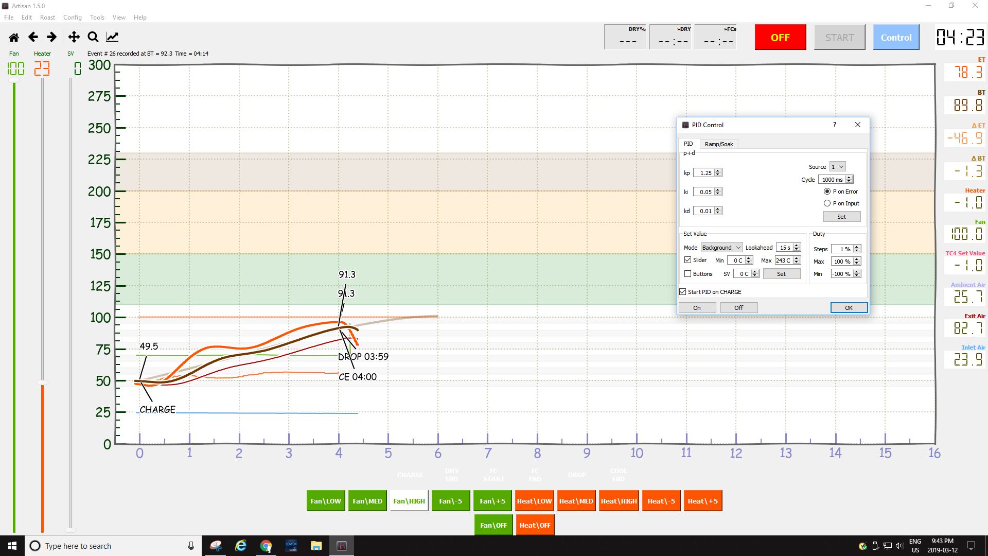
Graeme, thank you. I'm totally new at PID and the whole automation process. At first, without a visual aid, I was entering higher than necessary numbers in P and I and D inputs. My machine was all over the map... high spike, low spike, terrible. After many hours of trial runs on old greens and finally red beans (the chili type), I gave up. I did a lot of reading and YT still nothing. Then I read this page https://en.wikipe...controller and found the animated GIF about the middle of the page on the right side to be most helpful. Starting with the PID values all at 0 I did as shown, starting with a small P number... the rest comes easily following this method. The image I'm attaching is what worked for my machine. I may tweak it some, but it works quite good already.
CK attached the following image:
|
|
|
|
| JitterzZ |
Posted on 03/15/2019 12:04 AM
|
 1/4 Pounder  Posts: 151 Joined: October 08, 2018 |
Effects of varying PID parameters (Kp,Ki,Kd) on the step response of a system.
JitterzZ attached the following image:

|
|
|
|
| renatoa |
Posted on 03/15/2019 2:26 AM
|
|
Administrator Posts: 3104 Joined: September 30, 2016 |
Sincerely, this graph don't inspire me much confidence. PID values depends a lot of the process, and the conclusions of this animations are wrong for 99% of the processes I know. Actually, I think to a single case where these values could be appropriate, and even this is not a common situation we experience in the whole life: making a drift with a car  P and D simultaneously at same big value means nothing else than acceleration (P) and brake (D) pressed together, as I seen in a drift tutorial. Never experienced... As I wrote many times in the past, I am done with PID and profile following for coffee roasting, it's simply not the right control method for such process, period. Especially recovering after a TP is the nightmare of a PID, and a disaster when not tuned. A PID can't predict approaching the profile and TP event, to start increasing power, so usually ends into a profile undershot, followed by oscillations. Manually adjusting in this moment negates the automatic profile following idea. Check here some posts yesterday about an alternative approach of profiling a roast without PID. https://forum.hom...post_68211 Edited by renatoa on 03/15/2019 2:57 AM |
|
|
|
| CK |
Posted on 03/15/2019 3:29 PM
|
|
1/2 Pounder Posts: 252 Joined: December 07, 2018 |
Quote Graeme Lindsay wrote: BATCH SIZE I was looking at the power input and roast times that you posted. It looks as though you could have some spare power to potentially push the green bean weight even higher and still roast in a less than 12 minutes. Have you tried larger batch sizes yet or have you found the roast chamber not quite big enough, beans flow not ideal or they shoot out the exhaust? This machine has plenty of spare power but it is currently limited by the slim RC. The glass only has an 85mm inner diameter and about 210mm inner height. The most roasted so far was 350g... easily, in under 12 minutes. The problem comes with cooling the beans at the end. A higher fan output during cooling ejects some beans to the chaff cyclone. So the best balance is 300g. With 500g greens in the RC, the beans still loft well even without heat applied. I never roasted them because of the small RC... there's no room for expanding bean mass at 500g. The height of the green beans in the RC is about 150mm deep over the screen inlet, and I'm quite surprised the little fan works so well. I'm thinking of making a larger RC that can be modular to this roaster to up the batch sizes. |
|
|
|
| CK |
Posted on 03/19/2019 9:49 PM
|
|
1/2 Pounder Posts: 252 Joined: December 07, 2018 |
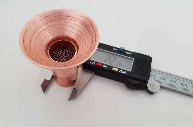
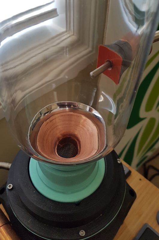
I've replaced the old silicone bean cone for a more resilient high-temperature copper and stainless steel bean cone. Works great. This allows the roaster to go to hotter drop temperatures.
CK attached the following images:

|
|
|
|
| MaKoMo |
Posted on 03/20/2019 12:25 PM
|
|
1/4 Pounder Posts: 127 Joined: April 06, 2011 |
Quote renatoa wrote: Especially recovering after a TP is the nightmare of a PID, and a disaster when not tuned. A PID can't predict approaching the profile and TP event, to start increasing power, so usually ends into a profile undershot, followed by oscillations. Manually adjusting in this moment negates the automatic profile following idea. Check here some posts yesterday about an alternative approach of profiling a roast without PID. https://forum.hom...post_68211 I agree that a PID will always struggle with the TP "effect" in a drum roaster profile, mostly because it is totally artificial. I haven't looked at your alternating approach, but what to say against an hybrid approach, where you use some event replay by time/temp or an alarm program up to DRY and the let a PID do the rest? You can even adjust p-i-d parameters over the second half of the roast, like using a different tuning from FCs on then before using a simple rule in Artisan. |
|
|
|
| revive |
Posted on 03/21/2019 10:06 AM
|
|
Newbie Posts: 2 Joined: July 11, 2011 |
Beautiful design. I actually came across your youtube vid before seeing your full breakdown of the build here.. excellent work! Out of curiosity, where did you source the cyclone from? And did you custom make the new copper copper and SS bean cone or are those off the shelf? Great work! |
|
|
|
| CK |
Posted on 03/21/2019 10:16 AM
|
|
1/2 Pounder Posts: 252 Joined: December 07, 2018 |
An upgrade for the roaster to quiet the machine down. These copper intake pipes bring air from inside the machine through holes in the bottom plate of the body. With the solid intake spacer ring, it now has a lower operating sound of 65 DB at 50% fan... quite comfortable to be around while roasting. (Before this modification, it was a loud 73-75 DB.)
CK attached the following image:

|
|
|
|
| CK |
Posted on 03/21/2019 11:02 AM
|
|
1/2 Pounder Posts: 252 Joined: December 07, 2018 |
Quote revive wrote: Out of curiosity, where did you source the cyclone from? And did you custom make the new copper cone and SS bean cone or are those off the shelf? The cyclone was bought here; https://www.amazo...&psc=1 The copper cone is an off the shelf 2" to 3/4" pipe reducer fitting bought here; https://www.amazo...&psc=1 It was cut, filed and then bonded to the SS cone. The SS cone was left over from another project. It too was cut and filed to custom specs for this RC. It was bought here; https://www.amazo...&psc=1 |
|
|
|
| revive |
Posted on 03/21/2019 2:26 PM
|
|
Newbie Posts: 2 Joined: July 11, 2011 |
Quote CK wrote: Quote revive wrote: Out of curiosity, where did you source the cyclone from? And did you custom make the new copper cone and SS bean cone or are those off the shelf? The cyclone was bought here; https://www.amazo...&psc=1 The copper cone is an off the shelf 2" to 3/4" pipe reducer fitting bought here; https://www.amazo...&psc=1 It was cut, filed and then bonded to the SS cone. The SS cone was left over from another project. It too was cut and filed to custom specs for this RC. It was bought here; https://www.amazo...&psc=1 Very nice, and very resourceful indeed!! I just noticed them, but your chambers are tapered...what did you use for them?? |
|
|
|
| CK |
Posted on 03/21/2019 4:10 PM
|
|
1/2 Pounder Posts: 252 Joined: December 07, 2018 |
Quote I just noticed them, but your chambers are tapered...what did you use for them?? https://www.ikea..../90279719/ |
|
|
|

| Jump to Forum: |
Powered by PHP-Fusion Copyright © 2024 PHP-Fusion Inc
Released as free software without warranties under GNU Affero GPL v3
Designed with ♥ by NetriXHosted by skpacman