
Login

Shoutbox
You must login to post a message.
renatoa
07/26/2024 3:49 PM
Bill grubbe and Jk, 
allenb
07/26/2024 5:15 AM
Spiderkw Welcome to HRO!

renatoa
07/24/2024 8:31 AM
ramiroflores and John123,

 ?
?
?renatoa
07/21/2024 1:18 AM
 , Luislobo
renatoa
07/19/2024 11:28 AM
Koepea,
Forum Threads
Newest Threads
Skywalker roaster modsBackground Roast Iss...
Hello from Arkansas
TC4ESP
Green coffee reviews
Hottest Threads
| Skywalker roaster... | [375] |
| TC4ESP | [115] |
| War on Farmers by... | [47] |
| Adventures in flu... | [26] |
| Hello! (soon) Roa... | [17] |
In Memory Of Ginny

Donations
Latest Donations
dmccallum - 10.00
JackH - 25.00
snwcmpr - 10.00
Anonymous - 2.00
Anonymous - 5.00
dmccallum - 10.00
JackH - 25.00
snwcmpr - 10.00
Anonymous - 2.00
Anonymous - 5.00
Users Online
Guests Online: 8
Members Online: 0
Total Members: 8,393
Newest Member: Bill grubbe
Members Online: 0
Total Members: 8,393
Newest Member: Bill grubbe
View Thread
Who is here? 1 guest(s)
Page 1 of 2: 12
|
 Make "CR3" part of TC4 family?
|
|
| mg512 |
Posted on 12/24/2018 1:05 PM
|
 1/4 Pounder  Posts: 189 Joined: March 04, 2018 |
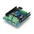
Hi all, as some of you know, I have made a TC4-like Arduino shield, so far codenamed "CR3". I began offering this to people on here earlier this year when the original TC4 became unavailable. The whole thing started very ad-hoc - there was people looking for boards, and I had a few extra ones left over. Going forward, I want to make things more thought through and clearer for everyone. To this end, I am thinking it would make sense to officially make the board part of the TC4 "family". It's a bit like the TC4C - the board is essentially a TC4 + extras. Hence I was thinking of renaming it "TC4X" or "TC4+" or similar. I am also planning to make the schematics and board layout files available on github under a CC-BY-NC-SA license, so that the project will stay available even if in the future I myself get tied up in other things (just want to sort out a proper name for the board before I do that). What do you all think? I realise that the TC4 is a community project, and I want to make sure that everyone is happy for me to get involved in this way. Cheers, Matthias |
|
|
|
| fransgo |
Posted on 12/24/2018 2:43 PM
|
|
Newbie  Posts: 4 Joined: February 28, 2018 |
Wonderful initiative! |
|
|
|
| renatoa |
Posted on 12/25/2018 2:39 AM
|
|
Administrator Posts: 3104 Joined: September 30, 2016 |
You are not alone, a TC4ESP will follow soon  |
|
|
|
| mg512 |
Posted on 12/25/2018 5:08 AM
|
|
1/4 Pounder Posts: 189 Joined: March 04, 2018 |
Ah, yes, I'm considering something like that in the long term too. ;) |
|
|
|
| JackH |
Posted on 12/25/2018 7:18 AM
|
 Administrator Posts: 1809 Joined: May 10, 2011 |
I think it is a good idea to keep a general family name and add extensions to show the differences. Thanks Matthias, for keeping it going, it is a worthy device. ---Jack
KKTO Roaster. |
|
|
|
| mg512 |
Posted on 12/30/2018 4:06 AM
|
|
1/4 Pounder Posts: 189 Joined: March 04, 2018 |
Thank you for your kind words, Jack.  And great - I take it everyone is happy for me to make this a TC4 variant. I am hereby naming the board the "TC4+" then. More updates to follow. |
|
|
|
| greencardigan |
Posted on 12/30/2018 5:11 AM
|
 1 1/2 Pounder  Posts: 1185 Joined: November 21, 2010 |
I agree that a variation of the TC4 name is a good idea. TC4+ sounds good to me. |
|
|
|
| CK |
Posted on 12/31/2018 8:28 PM
|
|
1/2 Pounder  Posts: 252 Joined: December 07, 2018 |
Good name choice. Creates anticipation for the extras this board has... |
|
|
|
| mg512 |
Posted on 01/05/2019 2:50 AM
|
|
1/4 Pounder Posts: 189 Joined: March 04, 2018 |
Great! Thank you, everyone, for the wonderful comments and encouragement. The TC4+ is now available on Tindie! https://www.tindi...no-shield/ And the source files are on Github: https://github.co...ter-shield |
|
|
|
| marcov |
Posted on 01/26/2019 3:07 AM
|
|
1/4 Pounder Posts: 61 Joined: January 21, 2019 |
Hey guys, it's great to hear about a potential TC4ESP. I'd suggest using the "new" ESP32 SoC. Are you thinking to leave the headers for Arduino so that it could still be used as shield? Probably this would make sense. I am willing to contribute at this porting or rewriting the existing aArtisan FW for the ESP. |
|
|
|
| mg512 |
Posted on 01/26/2019 4:03 PM
|
|
1/4 Pounder Posts: 189 Joined: March 04, 2018 |
Quote marcov wrote: Hey guys, it's great to hear about a potential TC4ESP. I'd suggest using the "new" ESP32 SoC. Are you thinking to leave the headers for Arduino so that it could still be used as shield? Probably this would make sense. I am willing to contribute at this porting or rewriting the existing aArtisan FW for the ESP. I have been using an ESP32 for a controller for my Gaggia Classic espresso machine, so I already have a lot of code for temperature control written for that, and some PCB designs. ;) What do you mean by Arduino headers? As in, put an Arduino header on the board and route it to some ESP32 pins? I don't think an ESP32 would easily work with Arduino shields for a variety of reasons, starting with different voltages. Or you mean make it a shield that could work with both ESP32 and Arduino? More or less the same technical obstacles apply. An additional thing there would be that there isn't a standardised pinout for ESP32 modules, like there is with the Arduino Uno platform, and no further "shield"-ecosystem around it for that reason. I think with an ESP (8266 or 32), it would make more sense to take the TC4C approach, and put the controller directly onto the board. Could still be programmed via USB and the Arduino IDE, and could retain full pinout for hooking up more hardware, of course. But making it a "shield" would just create confusion I think, if people don't get the exact same ESP board, their pinout might be completely different, and the shield wouldn't work. |
|
|
|
| renatoa |
Posted on 01/27/2019 2:37 AM
|
|
Administrator Posts: 3104 Joined: September 30, 2016 |
Me too evaluated using an ESP as an Arduino shield, and there is no benefit. I have no potential board to stack with this hypothetical shield, appealing enough to make me consider this way. There is a problem with ESP32 though, it is still not enough mature for such task. Tried to use it for the TC4ESP project and at least two big missing made me abandon it, and stick with the older ESP8266, at least for the first draft. This is unfortunate, because ESP32 features BT, a lot simpler to use for Artisan interface than MQTT approach. |
|
|
|
| JackH |
Posted on 01/27/2019 3:09 AM
|
|
Administrator Posts: 1809 Joined: May 10, 2011 |
Quote renatoa wrote: This is unfortunate, because ESP32 features BT, a lot simpler to use for Artisan interface than MQTT approach. Most people here do not understand these acronyms. Can you explain? Edited by JackH on 01/28/2019 6:32 PM ---Jack
KKTO Roaster. |
|
|
|
| marcov |
Posted on 01/27/2019 3:39 AM
|
|
1/4 Pounder Posts: 61 Joined: January 21, 2019 |
Quote mg512 wrote: What do you mean by Arduino headers? ... Or you mean make it a shield that could work with both ESP32 and Arduino? Correct, I thought that having a board that could be used either as an Arduino shield or as a standalone board (by populating it with a ESP-12 module) would be interesting. The main advantage that I see is that it would still be backward compatible with the existing Arduino implementations, and at the same time it would allow hackers to experiment something new Voltages difference is the most annoying thing. Level shifters are a solution, but would make the design not so attractive in the end. Quote Are you talking about ESP-32 specific features (e.g. BT) that are still not supported? Or is it lacking features even when compared to the old ESP8266? |
|
|
|
| marcov |
Posted on 01/27/2019 3:59 AM
|
|
1/4 Pounder Posts: 61 Joined: January 21, 2019 |
Quote JackH wrote: Quote renatoa wrote: This is unfortunate, because ESP32 features BT, a lot simpler to use for Artisan interface than MQTT approach. Most people here do not understand these acronym. Can you explain? BT is an abbreviation for Bluetooth. ESP32 is a chip containing in a single package a microcontroller, a WiFi radio and and a Bluetooth / Bluetooth low energy radio. You can buy ready-to-solder ESP-32 modules for as low as 3$, and ready-to-use development boards for 5$. MQTT is a protocol commonly used to read sensor data / write commands to ESP modules over WiFi. It's popular because it abstracts from devices addressing details (e.g. you dont need to know the IP of your WiFi node) and because writing code using MQTT is very easy. |
|
|
|
| renatoa |
Posted on 01/27/2019 4:03 AM
|
|
Administrator Posts: 3104 Joined: September 30, 2016 |
BT = Bluetooth, is supported, tried it and it works, even if not performed a full roast 15 minutes test, to be sure is connection does not drop. What I don't like about ESP32 is the Arduino compatibility, unfinished, and still in progress, somewhat... too slow addressing issues that seems never ending. Only the lack of AnalogWrite make many people thinking about ESP32 creators "what do they have in mind?!"... to cut the main PWM support that everyone that pretend to be compatible with Arduino must offer, to not lose 90% of mass projects already done. The replacement solution library offer is lame, people simply want the old known stuff. The most annoying part of this story is the incertitude seed in many people thoughts... "if they dropped AnalogWrite, what other many <Ester eggs> could be hidden elsewhere"... that could make me drop the project when I am near deadline... And they abandon using ESP32, as me. MQTT is an internet protocol: https://en.wikipe.../wiki/MQTT ... that seems to be established as the most preferred communication way in the IoT (Internet of Things) world, i.e. intelligent home devices. Unfortunately, MQTT is not so well supported in the PC world, not for average Joe. Lots of support from and to programmers/developers, but not so simple to use as plug an USB or pairing a Bluetooth device. So, to use MQTT with a roaster someone should install additional software (that is not yet written) as a bridge between Artisan or another traditional roasting software that wasn't been developed from the roots with intelligent sensors in mind. |
|
|
|
| mg512 |
Posted on 01/27/2019 7:30 PM
|
|
1/4 Pounder Posts: 189 Joined: March 04, 2018 |
Bear in mind that ESP32 is Bluetooth 4, aka Bluetoot Low Energy. This is not the same as classic Bluetooth, and in particular, at least as far as I know, doesn't have a simple Bluetooth Serial profile. As a consequence, I don't think it's possible to connect directly to an ESP32 in Artisan or similar, as it won't show up as a serial interface on the computer. So there would be some software development required on the Artisan or host computer side - at which point indeed one might as well go with WiFi and some IP based protocol, whether that be MQTT or something else. Personally I have found the Arduino ESP32 support perfectly fine. |
|
|
|
| JackH |
Posted on 01/28/2019 5:50 AM
|
|
Administrator Posts: 1809 Joined: May 10, 2011 |
Thanks for the explanation. I was trying to make things a bit clearer for everyone. Sometimes acronym-speak can be confusing.
---Jack
KKTO Roaster. |
|
|
|
| CharcoalRoaster |
Posted on 01/28/2019 8:02 AM
|
 1 1/2 Pounder Posts: 640 Joined: April 13, 2012 |
I recently picked up an Arduino Uno board and was about to purchase the TC4 before I saw this post. Can someone simplify for me what, if any, differences there are between these two board in a *simple* way? |
|
|
|
| mg512 |
Posted on 01/28/2019 1:27 PM
|
|
1/4 Pounder Posts: 189 Joined: March 04, 2018 |
Quote CharcoalRoaster wrote: I recently picked up an Arduino Uno board and was about to purchase the TC4 before I saw this post. Can someone simplify for me what, if any, differences there are between these two board in a *simple* way? The two main differences are: 1: The TC4+ has support for an optional Bluetooth module, if you want to connect to your roaster wirelessly. 2: For roasters that have a DC fan motor, the TC4+ has everything on board to control those, which makes things easier in those setups. This is especially relevant for many popcorn machine based roasters, though I have also heard of some other cases where a DC driver was useful. In a nutshell, your roaster's fan will be powered either by mains 110V/230V AC (alternating current), or by a lower-voltage DC (direct current). If it's AC, both the TC4 and TC4+ will work the same way (but both will require extra hardware, which you could buy pre-built, e.g. on Tindie). If it's DC, then the TC4+ has everything on-board to control the fan. The TC4 could still control a DC fan as well, but would require extra hardware (a small circuit, which you would have to build yourself). Or, in very simplified terms, TC4+ = TC4 + Bluetooth + DC fan control. |
|
|
|
| CharcoalRoaster |
Posted on 01/28/2019 2:38 PM
|
|
1 1/2 Pounder Posts: 640 Joined: April 13, 2012 |
Ok, great thanks. I also found your website info helpful. What is the extra hardware required for fan control? I'll be running a 120v vacuum blower |
|
|
|
| mg512 |
Posted on 01/28/2019 4:27 PM
|
|
1/4 Pounder Posts: 189 Joined: March 04, 2018 |
Quote CharcoalRoaster wrote: Ok, great thanks. I also found your website info helpful. What is the extra hardware required for fan control? I'll be running a 120v vacuum blower There is two ways you can do it. 1: The "ZCD + random-fire SSR" approach. You will need a ZCD / "zero-cross detector", and a "random-fire SSR". (Note that random-fire SSR is different than the more common zero-crossing SSR. If it's not specified, it's likely the latter!) This is the way it has commonly been done with the TC4. There is a ZCD made specifically for the TC4. I don't make these, but I believe greencardigan does, or at least has done at some point, and has them on Tindie. The random-fire SSR you could get from digikey, mouser, etc.; they might be harder to find on eBay or other sources, as they are less common than regular SSRs. 2: The "PWM dimmer module" approach. This is how I personally would go about it. You need a PWM dimmer module, which replaces both the ZCD and the random-fire SSR. You can get them on e.g. on Tindie: https://www.tindi...-50hz-60hz I personally prefer the PWM dimmer module approach, since it separates out all the AC dimming into a self-contained module - I think fewer things can go wrong this way, and it frees up some resources on the Arduino for other things. It is also slightly cheaper, I think, since the PWM dimmer module replaces both the ZCD and the random-fire SSR. But both approaches work well. For slightly more technical background: To control an AC fan, you can't just turn power on and off very quickly, as you would with a DC fan. Instead, the turning on and off has to be synchronised with the timing of the AC signal. Essentially, you want to switch the power on part-way through each half-sine wave of the AC signal, so you need to know when each wave starts. There is two ways of doing it. 1: With the "ZCD + random-fire SSR" approach, the ZCD devices generates a pulse every time the AC signal crosses zero (hence the name). This is sent to the Arduino, which in turn sends a signal to the random-fire SSR a certain time after receiving the pulse. The random-fire SSR then immediately switches on until the AC crosses zero again, and the cycle repeats. So the ZCD detects the zero-crossing, the Arduino keeps track of the timing, the random-fire SSR switches when told to. 2: With the "PWM dimmer module" approach, the Arduino switches on-and-off a signal very quickly, which is sent to the PWM dimmer module. PWM stands for pulse-width modulation, and refers to this switching on-and-off rapidly; pulse-width means how much of the signal is on and how much is off, which controls signal intensity. The PWM dimmer module detects the zero-crossing of the AC; it reads the PWM signal; and it switches the AC on at the right time. In this approach, the PWM dimmer modules detects zero-cross, keeps track of timing, and switches the AC; the Arduino only outputs the desired fan level as a PWM signal. If you want even more technical background, an obvious follow-up questions is, "What are zero-crossing SSRs then, and why is none if this an issue for controlling a heating element?". A zero-crossing SSR detects the AC zero-cross itself, and switches on exactly when the AC zero-cross occurs (if it is told to be "on"), and then stays on at least until the next zero-cross occurs. This is because switching AC on and off at other points in time can create various issues if you don't time it right, hence the zero-cross SSR does the timing for you. This is easier, but it means you can only switch your AC load on and off relatively slowly, or with relatively coarse-grained control. And indeed, the standard way the TC4 controls a heating element is by switching them on and off (via the zero-crossing SSR) once a second, leaving the heating on for a specified part of each second. This is OK: The heating element doesn't heat up or cool down much in the span of one second. But for a fan, switching it on for half a second and off for half a second would make for very choppy operation at best, hence something faster is required. With DC a straight PWM signal works, and with AC, chopping off part of each AC half-sine wave is the usual approach (same as an old-fashioned dimmer switch for your ceiling light). Now, the difference between a zero-crossing and random-fire SSR: A zero-crossing SSR switches on only when the AC crosses zero - if the input signal switches from off to on halfway through a half-sine wave, the SSR waits until the next zero-cross before it switches on. A random-fire SSR switches on immediately if the input signal changes from off to on. Hence the random-fire one can be used to time the switching on within each half-sine wave (but it requires you to handle the zero-cross detection and timing externally); but the zero-crossing one can't (but you don't have to worry about zero-cross or timing). And a PWM dimmer module combines the best of both - fine-graind, fast control, but no worrying about zero-cross or timing. |
|
|
|
| greencardigan |
Posted on 01/28/2019 10:50 PM
|
|
1 1/2 Pounder Posts: 1185 Joined: November 21, 2010 |
Just to add to what Matthias has said. The "PWM dimmer module" on Tindie is rated for 5A current. That's about 600 Watts on 120V or 1200 Watts on 240V. That should be ok for small vacuum cleaner motors. |
|
|
|
| renatoa |
Posted on 01/29/2019 1:43 AM
|
|
Administrator Posts: 3104 Joined: September 30, 2016 |
The BT139-600 triac used in the Tindie project is rated for 16A. So 5A limitation come from heatsink only, can be raised with a greater heatsink. |
|
|
|
| CharcoalRoaster |
Posted on 01/29/2019 8:43 AM
|
|
1 1/2 Pounder Posts: 640 Joined: April 13, 2012 |
Is there a need for use of an external PID in combination with these boards? If used in conjunction with Artisan/something like it, the boards handle control of the roast profile? Or, are they just data tracking/logging? |
|
|
|

Page 1 of 2: 12
| Jump to Forum: |
Powered by PHP-Fusion Copyright © 2024 PHP-Fusion Inc
Released as free software without warranties under GNU Affero GPL v3
Designed with ♥ by NetriXHosted by skpacman