
Login

Shoutbox
You must login to post a message.
renatoa
07/26/2024 3:49 PM
Bill grubbe and Jk, 
allenb
07/26/2024 5:15 AM
Spiderkw Welcome to HRO!

renatoa
07/24/2024 8:31 AM
ramiroflores and John123,

 ?
?
?renatoa
07/21/2024 1:18 AM
 , Luislobo
renatoa
07/19/2024 11:28 AM
Koepea,
Forum Threads
Newest Threads
Background Roast Iss...Skywalker roaster mods
Hello from Arkansas
TC4ESP
Green coffee reviews
Hottest Threads
| Skywalker roaster... | [374] |
| TC4ESP | [115] |
| War on Farmers by... | [47] |
| Adventures in flu... | [26] |
| Hello! (soon) Roa... | [17] |
In Memory Of Ginny

Donations
Latest Donations
dmccallum - 10.00
JackH - 25.00
snwcmpr - 10.00
Anonymous - 2.00
Anonymous - 5.00
dmccallum - 10.00
JackH - 25.00
snwcmpr - 10.00
Anonymous - 2.00
Anonymous - 5.00
Users Online
Guests Online: 5
Members Online: 0
Total Members: 8,393
Newest Member: Bill grubbe
Members Online: 0
Total Members: 8,393
Newest Member: Bill grubbe
View Thread
Who is here? 1 guest(s)
 Need help rewiring new popper
|
|
| marcov |
Posted on 02/20/2019 11:55 AM
|
|
1/4 Pounder  Posts: 61 Joined: January 21, 2019 |
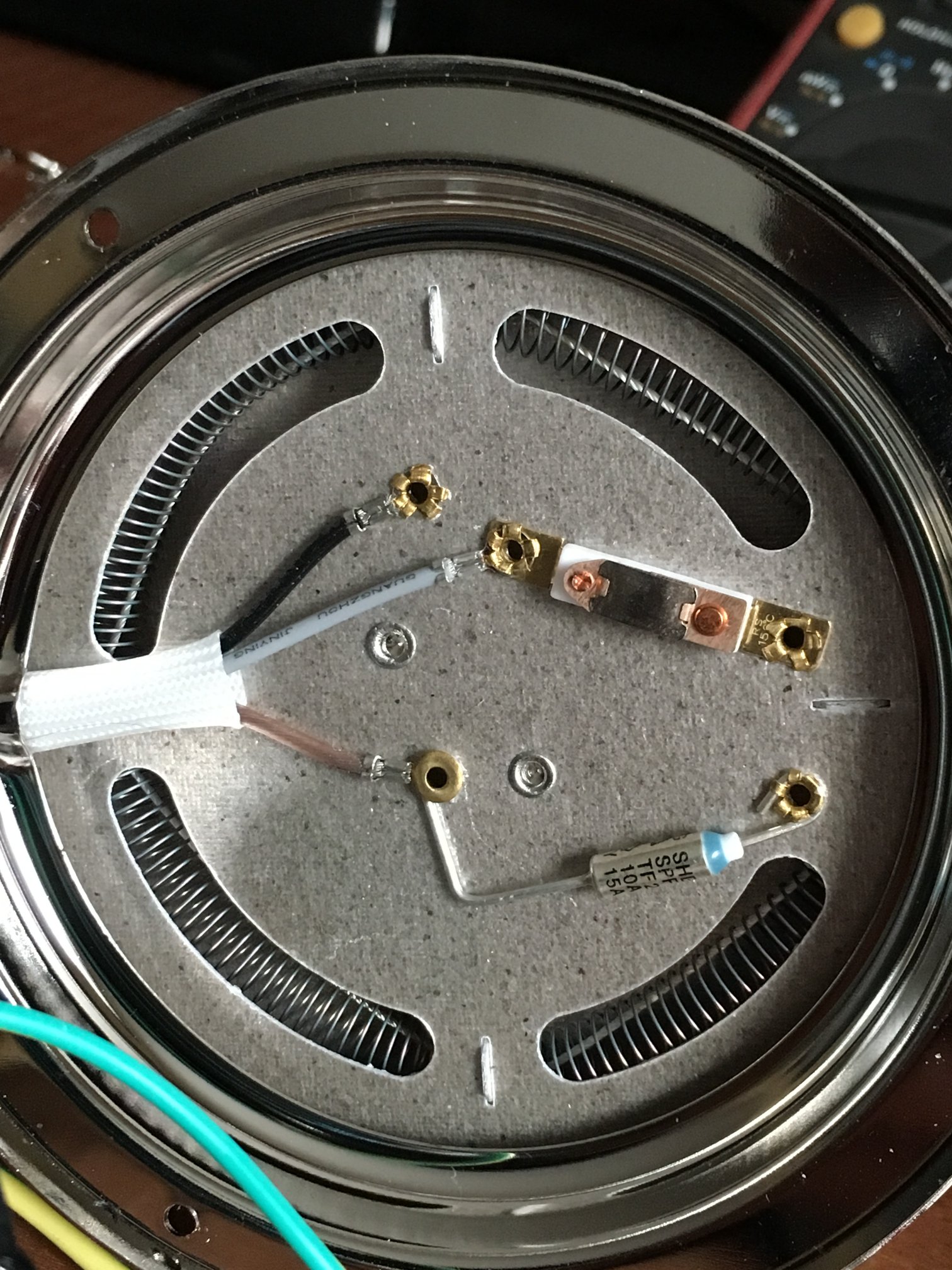
Hi, I just bought a popper with the only goal to roast coffee. I need some help with the rewiring. My goal is to control the heating element with a zero-cross SSR and the fan using a MOSFET. I am attaching the schematic I reverse engineered and picture of the heating element. This is an european popper, 220V 50Hz (Severin PC 3751). Some of the questions I have are: - Should I short/bypass the thermal fuse and the thermostat? - Should the 2 heating coils be kept in series and supplied with the SSR? - Can I plug the DC supply/MOSFET to the motor directly? Should the 3 capacitors be kept? - I measured 19VDC at the motor terminal. Is it ok to supply the motor using 25VDC?
marcov attached the following images:

|
|
|
|
| renatoa |
Posted on 02/20/2019 1:08 PM
|
|
Administrator Posts: 3104 Joined: September 30, 2016 |
1. Bypass thermostat only, keep the fuse 2. Yes, keep. Removing the 8 Ohms motor coil will overload the main heater with about 16% more voltage => 35% more power, less life. 3. Yes, directly is fine. The capacitors, together with L1/L2, are brush spark filters and should be let there. 4. ok is a relative term...  clearly motor life will be decreased, but we want more airflow, so... Those motors are usually RS385, rated for 24V, check attached datasheet. clearly motor life will be decreased, but we want more airflow, so... Those motors are usually RS385, rated for 24V, check attached datasheet....
renatoa attached the following file:
|
|
|
|
| marcov |
Posted on 02/20/2019 1:21 PM
|
|
1/4 Pounder Posts: 61 Joined: January 21, 2019 |
Thank you renatoa! I'm really looking forward to the first roast |
|
|
|
| marcov |
Posted on 03/05/2019 3:27 PM
|
|
1/4 Pounder Posts: 61 Joined: January 21, 2019 |
I progressed in my modding and now I have almost everything ready for a first roast. However I have quite a big problem bothering me: when the DC fan motor on, reading from TCs are very erratic and almost garbage at ambient temperature. Strangely enough, if I keep my laptop close by the trackpad too seems to be affected by EMI (electromagnetic interferences) and have behaves poorly when trying to move the pointer. To add some more information, I am using the cheapest (chinese) 24V switching DC power supply you can find on amazon, and a TC4+ board. I am not sure if: - the problem is with the motor or the supply (when heavily loaded) emitting EMI. - the reason of the erratic measures is the ADC on the board or the TCs picking up EMI. However, I did try to read the temperature from TC with a cheap multimeter, and in this case I did not observe this behaviour. Do you have any suggestion of what I can do? Could the 2 inductors in series to the motor cause this (see pic in the first post). |
|
|
|
| renatoa |
Posted on 03/05/2019 3:35 PM
|
|
Administrator Posts: 3104 Joined: September 30, 2016 |
Are the TC wires shielded/not ? If shielded, is the mesh grounded? and how ? How is the TC4 powered, via usb or own power source ? |
|
|
|
| marcov |
Posted on 03/05/2019 4:19 PM
|
|
1/4 Pounder Posts: 61 Joined: January 21, 2019 |
Quote Yes, they are shielded with metal sleeves, and NO, sleeves are not grounded. Quote renatoa wrote: How is the TC4 powered, via usb or own power source ? Powered with the same 24V power supply used for the motor. Thanks for replying ;) |
|
|
|
| renatoa |
Posted on 03/06/2019 1:45 AM
|
|
Administrator Posts: 3104 Joined: September 30, 2016 |
I would try to power TC4 from other source, usb, whatever... If that source is low current, like 1A, you could be surprised to hear that motor chops the output voltage with huge spikes. This can be easily found measuring source voltage under load, and see how severe is the drop. If current draw of the motor is matched with source capabilities, the voltage drop should be unnoticeable, under 0.1V. |
|
|
|
| marcov |
Posted on 03/06/2019 8:04 AM
|
|
1/4 Pounder Posts: 61 Joined: January 21, 2019 |
Hi, so I tried to supply the TC4 with a 12V adapter. Still, the GND of the 24V needs to be connected to the TC4 to switch the IO3 MOSFET. After some more investigation I found that grounding TC shields makes things much better. Thanks for the hint. However I am still troubleshooting what to do exactly, because: - when using 2 TCs, if I ground the shields to GND for both, one of the 2 is off goes off by 10C. Maybe that TC is grounded... - when grounding the shield of just one of the 2, everything is OK until I plug the heater plug. When I plug it, one of the 2 TC goes off again of around 10C. Note that this happens without actually the heater being switched ON by the SSR, just the 220V plug being in the socket. I suspect this is because of a ground loop, but I am not sure how to fix it. Probably I'll just live with it. Edited by marcov on 03/06/2019 12:06 PM |
|
|
|
| marcov |
Posted on 03/06/2019 12:04 PM
|
|
1/4 Pounder Posts: 61 Joined: January 21, 2019 |
Quote marcov wrote: - when using 2 TCs, if I shield both one of the 2 is off goes off by 10C. Maybe that TC is grounded... - when shielding just one of the 2, everything is OK until I plug the heater plug. When I plug it, So, I think it makes sense not to ground both TCs at their base. TCs heads are both touching the metal basket of the popper, so their shields are connected to GND anyway. If I connect to GND both shields at the TC base, I am creating a big GND loop that is picking up noise. All this is kind of weird. When connecting the TC to my multimeter, I dont get all this issues. I am not sure if the ADC or the TC4 board is the culprit here. |
|
|
|
| greencardigan |
Posted on 03/06/2019 2:46 PM
|
 1 1/2 Pounder  Posts: 1185 Joined: November 21, 2010 |
Try grounding the TC4 board. There's a 2 pin header on the board you can connect a ground wire to. |
|
|
|
| marcov |
Posted on 03/06/2019 2:52 PM
|
|
1/4 Pounder Posts: 61 Joined: January 21, 2019 |
Quote greencardigan wrote: Try grounding the TC4 board. There's a 2 pin header on the board you can connect a ground wire to. Grounding to what? |
|
|
|
| greencardigan |
Posted on 03/06/2019 3:34 PM
|
|
1 1/2 Pounder Posts: 1185 Joined: November 21, 2010 |
I have mine grounded to mains ground. |
|
|
|
| marcov |
Posted on 03/09/2019 9:40 AM
|
|
1/4 Pounder Posts: 61 Joined: January 21, 2019 |
Thanks for the tips. In the end I figured out the problem and how to fix it. The problem is indeed that 12$ 24V 5A chinese power supply bought on Amazon. The fixes are: - Connect the power supply V- the mains ground (earth). - Add 1uF, 10uF, 100uF between V- and V+. - Use the power supply for the fan, but supply the TC4 with another supply. - Ground TC metal sleeves. Started to play roasting a couple of batches... now I actually need to learn how to roast! |
|
|
|
| marcov |
Posted on 03/10/2019 9:43 AM
|
|
1/4 Pounder Posts: 61 Joined: January 21, 2019 |
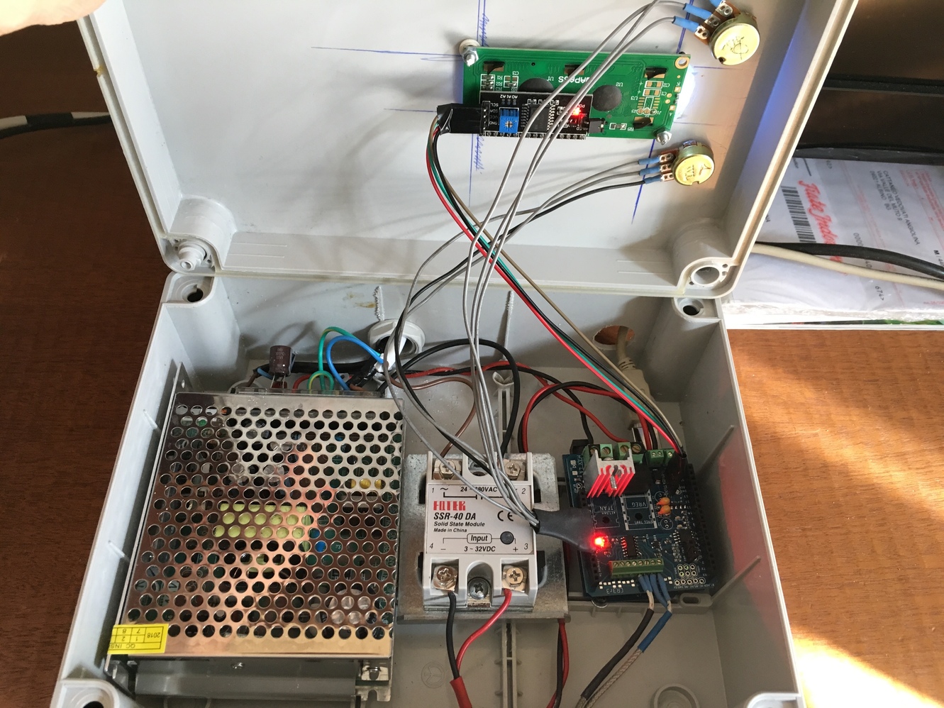
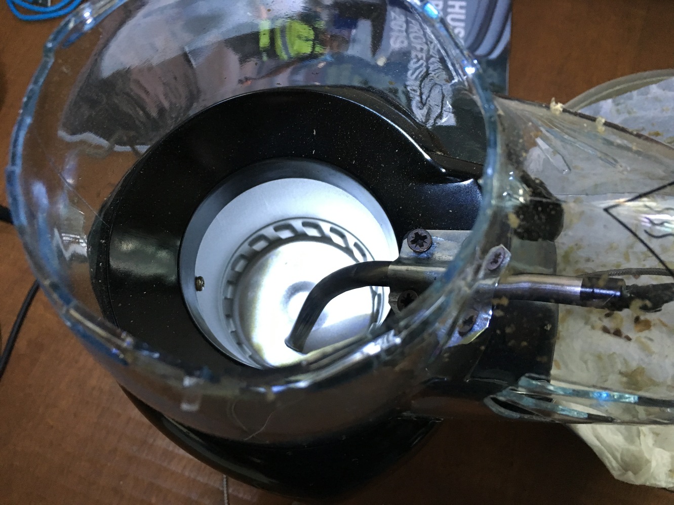
Adding some pictures with a semi-finished build. I need to find some longer TC probes to have less wires around.
marcov attached the following images:

|
|
|
|
| renatoa |
Posted on 03/10/2019 10:12 AM
|
|
Administrator Posts: 3104 Joined: September 30, 2016 |
That probe is too much into direct airflow stream, imo... I would raise it at least to be in the middle height of beans mass. And centered in the vortex. |
|
|
|
| marcov |
Posted on 03/10/2019 11:52 AM
|
|
1/4 Pounder Posts: 61 Joined: January 21, 2019 |
I'll fix that, thanks! BTW, I noted that in the center the beans moves much slower, curious to see if putting the probe there will change anything. |
|
|
|
| renatoa |
Posted on 03/11/2019 2:20 AM
|
|
Administrator Posts: 3104 Joined: September 30, 2016 |
Please be aware there are big differences in airflow pattern for the two main fluid bed machine approach: - the poppers, where the air column is a vortex, as in a tornado, faster near the walls, and almost still in the center (that's why is best to have probe there) - the others, based on hot gun blowers, air comes vertically through a funnel in the bottom. The central column is the most turbulent area in the roast chamber in this case, the best probe placement being in a corner between the wall and funnel start, out of reach of the main hot air jet. |
|
|
|
| marcov |
Posted on 03/11/2019 7:28 AM
|
|
1/4 Pounder Posts: 61 Joined: January 21, 2019 |
That makes a lot of sense! The center of the tornado is supposed to be calm, so the same applies here. |
|
|
|
| Gullygossner |
Posted on 03/27/2019 10:33 AM
|
|
1/4 Pounder Posts: 95 Joined: January 06, 2019 |
Quote Curious what your setup to ground the TC metal sleeves looks like. I am using a max31855 connected to an arduino. Everything reads fine until any portion of the thermocouple comes in contact with metal within my popper. I tried grounding the metallic portion of the popper to mains but that did not solve the issue which leads me to believe the sleeve of thermocouple may need to be grounded? |
|
|
|
| marcov |
Posted on 03/27/2019 11:32 AM
|
|
1/4 Pounder Posts: 61 Joined: January 21, 2019 |
I posted some pictures above. It is a TC4+ board with the MCP3424 ADC. I think the main source of the noise was the cheap 24V switching regulator used to supply the DC fan. After some tests I ended up grounding TC sleeves and also shorting V- to main's earth. Did you ground to earth the metal of your popper? |
|
|
|
| Gullygossner |
Posted on 03/27/2019 12:07 PM
|
|
1/4 Pounder Posts: 95 Joined: January 06, 2019 |
I studied your photos but I could not see how or what the TC sleeves were grounded to. I tried grounding the metal of the popper to earth via the mains power with no success. I do not have any switching regulator in my setup. 110v heater, 110v fan and the arduino is powered via my macbook air which is running on battery power during operation. |
|
|
|
| marcov |
Posted on 03/27/2019 12:36 PM
|
|
1/4 Pounder Posts: 61 Joined: January 21, 2019 |
My TC sleeves are tied to the metal parts of the popper, hence they are grounded. I suggest you anyway to keep the metal of your popper grounded to earth for your safety. I played around a bit before finding a solution that worked for me. Start by trying to undertand what's the source of your bad readings, so that you know what needs to be fixed. |
|
|
|
| renatoa |
Posted on 03/27/2019 12:41 PM
|
|
Administrator Posts: 3104 Joined: September 30, 2016 |
Or use unshielded probes. If not a noisy medium, like brushed motors in the proximity, then unshielded works fine. I am using unshielded probe in my roaster with under 0.1 C reading stability. |
|
|
|
| Gullygossner |
Posted on 03/27/2019 12:51 PM
|
|
1/4 Pounder Posts: 95 Joined: January 06, 2019 |
I will ground the metalic body of the popper again and see what happens. I started out with a shielded probe but figured that was the source of my issue so cut the probe off and tried with exposed thermocouple ends. I have a feeling that the AC fan is the source of the issue, but rectifying the problem has been puzzling. |
|
|
|
| rrgudur |
Posted on 08/10/2020 2:11 AM
|
|
Newbie  Posts: 1 Joined: August 10, 2020 |
Quote marcov wrote: Adding some pictures with a semi-finished build. I need to find some longer TC probes to have less wires around. Hi! Total Noob question. How did you connect the pots? and how do they work? Are they similar to sliders on Artisan-scope? Thanks |
|
|
|

| Jump to Forum: |
Powered by PHP-Fusion Copyright © 2024 PHP-Fusion Inc
Released as free software without warranties under GNU Affero GPL v3
Designed with ♥ by NetriXHosted by skpacman