
Login

Shoutbox
You must login to post a message.
renatoa
07/26/2024 3:49 PM
Bill grubbe and Jk, 
allenb
07/26/2024 5:15 AM
Spiderkw Welcome to HRO!

renatoa
07/24/2024 8:31 AM
ramiroflores and John123,

 ?
?
?renatoa
07/21/2024 1:18 AM
 , Luislobo
renatoa
07/19/2024 11:28 AM
Koepea,
Forum Threads
Newest Threads
Skywalker roaster modsBackground Roast Iss...
Hello from Arkansas
TC4ESP
Green coffee reviews
Hottest Threads
| Skywalker roaster... | [375] |
| TC4ESP | [115] |
| War on Farmers by... | [47] |
| Adventures in flu... | [26] |
| Hello! (soon) Roa... | [17] |
In Memory Of Ginny

Donations
Latest Donations
dmccallum - 10.00
JackH - 25.00
snwcmpr - 10.00
Anonymous - 2.00
Anonymous - 5.00
dmccallum - 10.00
JackH - 25.00
snwcmpr - 10.00
Anonymous - 2.00
Anonymous - 5.00
Users Online
Guests Online: 5
Members Online: 0
Total Members: 8,393
Newest Member: Bill grubbe
Members Online: 0
Total Members: 8,393
Newest Member: Bill grubbe
View Thread
Who is here? 1 guest(s)
 TC4ESP
|
|
| renatoa |
Posted on 10/28/2021 2:53 AM
|
|
Administrator Posts: 3104 Joined: September 30, 2016 |
True, there is no step by step setup manual, there are some warnings in the introductory post about the advanced level of forensic needed to build such project. Maybe will do such manual together  First lesson... this project is a TC4 clone, it walks and quacks as a TC4, Modbus is just an extra, and you should forget about it for now. So for the setup, Artisan side, read all you find about TC4, for example the greencardigan video. |
|
|
|
| zamunda |
Posted on 10/28/2021 3:39 AM
|
 1/4 Pounder  Posts: 173 Joined: November 17, 2020 |
Quote renatoa wrote: True, there is no step by step setup manual, there are some warnings in the introductory post about the advanced level of forensic needed to build such project. Maybe will do such manual together I am aware that TC4ESP it is not a "plug-and-play" solution... No problem in helping to write a manual, but before doing that, first need a better understanding of how it works Quote First lesson... this project is a TC4 clone, it walks and quacks as a TC4, Modbus is just an extra, and you should forget about it for now. So for the setup, Artisan side, read all you find about TC4, for example the greencardigan video. OK, your point is clear...will look at the greencardigan video... BTW: the Bluetooth-option works? If yes, I could connect a HC-06 and test it from the start as well... Also considering getting the LCD and buttons, if that would give me a more "out-of-the-box"-solution. Thanks and keep you posted. ########################
### A lot can happen over coffee ### ######################## |
|
|
|
| renatoa |
Posted on 10/28/2021 6:17 AM
|
|
Administrator Posts: 3104 Joined: September 30, 2016 |
Bluetooth works, but for connecting greencardigan Android app, not for Artisan wireless serial connection on a laptop. However, to activate this BT mode you need to press a button at startup... or modify the code. To help you start without buttons, nor recompile, add a wire jumper between A0 pin and any unused of the 3.3V pins. With this trick, and TC4 setup in Artisan done properly, you should be able to have an Artisan connection capable to control the heater, at least. |
|
|
|
| zamunda |
Posted on 10/28/2021 12:53 PM
|
|
1/4 Pounder Posts: 173 Joined: November 17, 2020 |
Hello Renatoa, After adding the jumper as you indicated, I configured the setup, following the vid of greencardigan (very good): https://www.youtube.com/watch?v=0-Co-pXF2NM In his video, I can see the value changing of the heater when moving the heater-slider, however, in my case, nothing happens there (see screenshot). Also the led on the SSR keeps blinking as before at a constant rate. So there is no interaction between the slider and the SSR yet... Any ideas? Thanks!
zamunda attached the following image:

########################
### A lot can happen over coffee ### ######################## |
|
|
|
| renatoa |
Posted on 10/28/2021 2:16 PM
|
|
Administrator Posts: 3104 Joined: September 30, 2016 |
Did you configured the slider event as in the attached image ? SSR blinking is suspicious, though... ...
renatoa attached the following image:

|
|
|
|
| zamunda |
Posted on 10/28/2021 3:00 PM
|
|
1/4 Pounder Posts: 173 Joined: November 17, 2020 |
Quote Yes I did... ########################
### A lot can happen over coffee ### ######################## |
|
|
|
| renatoa |
Posted on 10/29/2021 2:00 AM
|
|
Administrator Posts: 3104 Joined: September 30, 2016 |
The normal behaviour should be to have LED off at start, and blinking when moving the slider to any position, except zero. Should go off again when slider down to zero. |
|
|
|
| zamunda |
Posted on 10/29/2021 2:01 AM
|
|
1/4 Pounder Posts: 173 Joined: November 17, 2020 |
Hello, Today I heard from Aliexpress that my order for the AD8495 was refused by customs and sent back to the seller (without any specific reason), money will be reimbursed I suppose. In order not to wait another 4 weeks decided to buy the AD8495 now in Europe, double price but delivered within 1-2 days. However, the board looks a bit different... Could you confirm this is the same technically? Thanks!
zamunda attached the following image:
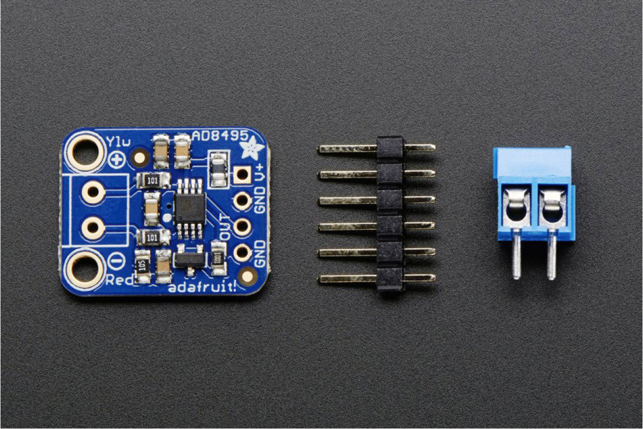
########################
### A lot can happen over coffee ### ######################## |
|
|
|
| zamunda |
Posted on 10/29/2021 2:05 AM
|
|
1/4 Pounder Posts: 173 Joined: November 17, 2020 |
Quote renatoa wrote: The normal behaviour should be to have LED off at start, and blinking when moving the slider to any position, except zero. Should go off again when slider down to zero. That was what I expected somehow, will do some more testing today...and the blinking rate should go up and down accordingly as well I suppose? Thanks! ########################
### A lot can happen over coffee ### ######################## |
|
|
|
| renatoa |
Posted on 10/29/2021 2:17 AM
|
|
Administrator Posts: 3104 Joined: September 30, 2016 |
The duty should vary, i.e. the ratio between on/off, the period is fixed, one second. Small changes are unnoticeable visually, you should have a large value jump, like 25-75% to see the change in the on/off ratio. |
|
|
|
| zamunda |
Posted on 10/29/2021 2:18 AM
|
|
1/4 Pounder Posts: 173 Joined: November 17, 2020 |
Hello, Progress! Just reconnected the setup per USB to my computer, opened Artisan and now the SSR responds to the slider! What I see now: - When setting slider to '0', SSR stops blinking: good! - When moving the slider, value changes but blinking rate on SSR remains the same: good! - When setting the slider value > 80 the value showed at the right remains '80', any idea why? And why is the ambient value showing '25'? Thanks again!
zamunda attached the following images:

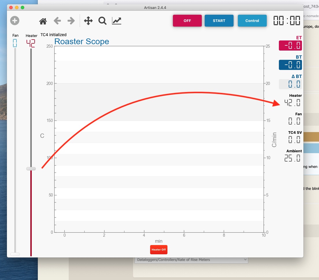
########################
### A lot can happen over coffee ### ######################## |
|
|
|
| zamunda |
Posted on 10/29/2021 2:33 AM
|
|
1/4 Pounder Posts: 173 Joined: November 17, 2020 |
Hello, Quote renatoa wrote: The duty should vary, i.e. the ratio between on/off, the period is fixed, one second. Small changes are unnoticeable visually, you should have a large value jump, like 25-75% to see the change in the on/off ratio. You're right, large jumps makes evident difference in duties... However, I noticed that the heater-value at the right varies but does not pass '80' and does not go below '40', it only reacts if slider > 40 and < 80. Is this a setting? Thanks! Edited by zamunda on 10/29/2021 1:26 PM ########################
### A lot can happen over coffee ### ######################## |
|
|
|
| renatoa |
Posted on 10/29/2021 3:28 AM
|
|
Administrator Posts: 3104 Joined: September 30, 2016 |
Yes, MIN/MAX_OT1 in user.h Time for some TC4 lessons |
|
|
|
| miyankizu |
Posted on 11/02/2021 2:11 AM
|
|
Newbie  Posts: 10 Joined: August 10, 2021 |
Hello friends is this okay for ad8495 ? US $6.92 44? Off | Amplifier Module Thermocouple Type K Electronic Component Board AD8495 ARMZ https://a.aliexpress.com/_vqm44E |
|
|
|
| zamunda |
Posted on 11/02/2021 2:13 AM
|
|
1/4 Pounder Posts: 173 Joined: November 17, 2020 |
Hello, The thermocouples arrived and so I started soldering the pins, was my first experience with soldering but went out right I think. Connected this set-up to Artisan and heater control is working as before... However, BT and ET still show "-0.0" values (only connected one TC). Do I have to recompile since I am using K-type? Or could there be any other reason temp is not showing yet?
zamunda attached the following images:


########################
### A lot can happen over coffee ### ######################## |
|
|
|
| zamunda |
Posted on 11/02/2021 2:13 AM
|
|
1/4 Pounder Posts: 173 Joined: November 17, 2020 |
Hello, Found this in user.h //////////////////// // Thermocouple Input Options // TC type is selectable by input channel // permissable options: typeT, typeK, typeJ #define TC_TYPE1 tcLinear //#define TC_TYPE2 typeK //#define TC_TYPE3 ... //#define TC_TYPE4 ... ..guess this should be read: #define TC_TYPE1 typeK //#define TC_TYPE2 typeK //#define TC_TYPE3 ... //#define TC_TYPE4 ... ...if using CH1???? ########################
### A lot can happen over coffee ### ######################## |
|
|
|
| renatoa |
Posted on 11/02/2021 2:13 AM
|
|
Administrator Posts: 3104 Joined: September 30, 2016 |
typeK is for the original TC4 design, where you connect the TC(s) directly to ADC input(s). For the TC amp used in TC4ESP you have to use tcLinear option. This option assume there is a hardware, like a TC dedicated amp, who performs the scale linearization, because the type K TC has a S shaped scale. Also, that hardware performs cold junction compensation, which for original TC4 is done by software. The result of the signal processing above is a voltage that shows directly the temperature for the whole scale, 5mV for each Celsius degree, voltage that needs just to be measured, and no further processing needed. The most immediate advantage is speed, only 70 ms needed for a measurement, compared to 300 ms for TC4. Edited by renatoa on 11/02/2021 4:41 AM |
|
|
|
| zamunda |
Posted on 11/02/2021 2:14 AM
|
|
1/4 Pounder Posts: 173 Joined: November 17, 2020 |
Hello Renatoa, Quote typeK is for the original TC4 design, where you connect the TC(s) directly to ADC input(s). For the TC amp used in TC4ESP you have to use tcLinear option. This option assume there is a hardware, like a TC dedicated amp, who performs the scale linearization, because the type K TC has a S shaped scale. Also, that hardware performs cold junction compensation, which for original TC4 is done by software. The result of the signal processing above is a voltage that shows directly the temperature for the whole scale, 5mV for each Celsius degree, voltage that needs just to be measured, and no further processing needed. The most immediate advantage is speed, only 70 ms needed for a measurement, compared to 300 ms for TC4. Thanks for your reply...so for the AD8495, I have to use "tcLinear"? and connect 1 cable from "out" to CH1+ according the documentation (https://github.com/renatoa/TC4-shield/blob/master/hardware/TC4ESP/TC4ESP-SSR_bb.jpg)? That is what I tested but did not gave me any results within Artisan... Thanks for any hints... Regards ########################
### A lot can happen over coffee ### ######################## |
|
|
|
| renatoa |
Posted on 11/02/2021 2:16 AM
|
|
Administrator Posts: 3104 Joined: September 30, 2016 |
Not only ONE cable... you have to connect all of them, that drawing is just for the signal paths, powering the modules is implied. Also, please note for the AD module only, there is need for a custom connection to ADC, how to and reason explained here: https://github.co...warning.md Edited by renatoa on 11/02/2021 4:40 AM |
|
|
|
| zamunda |
Posted on 11/02/2021 4:04 AM
|
|
1/4 Pounder Posts: 173 Joined: November 17, 2020 |
Quote renatoa wrote: Not only ONE cable... you have to connect all of them, that drawing is just for the signal paths, powering the modules is implied. Also, please note for the AD module only, there is need for a custom connection to ADC, how to and reason explained here. OK, you're right, you mean this info I guess: https://github.com/renatoa/TC4-shield/blob/master/hardware/TC4ESP/AD849x%20connecting%20warning.md https://github.com/renatoa/TC4-shield/blob/master/hardware/TC4ESP/Amp-ADC%20connection.jpg I will look into it and try to get it worked. Thanks! ########################
### A lot can happen over coffee ### ######################## |
|
|
|
| Will2 |
Posted on 11/04/2021 3:34 PM
|
 1/4 Pounder Posts: 154 Joined: March 24, 2015 |
I apologize for not communicating with you often enough. I have many other responsibilities. In April 2021, I did several experiments with TC4ESP. Not everything worked for me, I don't remember exactly. 
Viliam
|
|
|
|
| Will2 |
Posted on 11/06/2021 3:18 PM
|
|
1/4 Pounder Posts: 154 Joined: March 24, 2015 |
I should add information to the previous post. I haven't tried since April. At that time, if I remember correctly, ESP did not communicate with the Artisan roaster scope application. Although through the same computer through the serial monitor the response was correct. Today I tried connecting from another laptop, it works. I am also aware that I cannot use potentiometers, ie analog control. For me, button operation is not very intuitive. If I need to decide quickly, I never know which button and how long to press. Maybe the reason is that I have my habits of using TC4 and fluidbed roaster. Then I still miss that I can't use phase angle control for the fan. As you know, I use a fluid motor for a vacuum cleaner. Never mind, I'll use "PWM 2A AC Light Dimmer LED 50Hz 60Hz" instead. What I really like about TC4ESP and I consider it a great advantage is the ability to move the points for cold end measurements closer to the k-type terminals. On the contrary, I do not need Wifi or Bluetooth from ESP. So I would combine the benefits of TC4ESP and old TC4 by using newer boards, maybe different Arduino, with higher memory and the possibility of analog inputs. So that I keep Brad's aArtisanQ_PID as much as possible and it would be enough to upload only one sketch to Arduino, then switch my buttons to 3 modes: stand alone, artisan, android. I haven't roasted coffee with TC4ESP yet, if I have enough time, I'll either continue to try roasting TC4ESP + fluidbed roaster. Viliam
|
|
|
|
| renatoa |
Posted on 11/06/2021 4:40 PM
|
|
Administrator Posts: 3104 Joined: September 30, 2016 |
You can use analog pots, if connecting them to CH3/CH4 of ADC, supposedly unused for temperatures, and activate this alternate use of CH3/4 with ANLG1ADC3 / ANLG2ADC4 defines. The pots used for this purpose should be trimmed to output 0-2V for the whole rotating range, corresponding to 0-100 values of HTR/FAN. Combined usage of buttons/pot is possible, for example buttons for heater with a pot for the fan, or viceversa. Just activate the ch3 or ch4 only. Edited by renatoa on 11/06/2021 4:48 PM |
|
|
|
| renatoa |
Posted on 11/06/2021 4:45 PM
|
|
Administrator Posts: 3104 Joined: September 30, 2016 |
A notice for the both setups shown these days: you are stressing too much the usb plug on the ESP boards, imo. You risk broke of the PCB and traces exfoliating. Please ensure a support for the cable weight as close to the board as possible. |
|
|
|
| CamMor89 |
Posted on 11/08/2021 6:14 AM
|
|
Newbie Posts: 10 Joined: April 06, 2021 |
Does this work with ESP32? |
|
|
|

| Jump to Forum: |
Powered by PHP-Fusion Copyright © 2024 PHP-Fusion Inc
Released as free software without warranties under GNU Affero GPL v3
Designed with ♥ by NetriXHosted by skpacman