
Login

Shoutbox
You must login to post a message.
renatoa
07/26/2024 3:49 PM
Bill grubbe and Jk, 
allenb
07/26/2024 5:15 AM
Spiderkw Welcome to HRO!

renatoa
07/24/2024 8:31 AM
ramiroflores and John123,

 ?
?
?renatoa
07/21/2024 1:18 AM
 , Luislobo
renatoa
07/19/2024 11:28 AM
Koepea,
Forum Threads
Newest Threads
Skywalker roaster modsBackground Roast Iss...
Hello from Arkansas
TC4ESP
Green coffee reviews
Hottest Threads
| Skywalker roaster... | [375] |
| TC4ESP | [115] |
| War on Farmers by... | [47] |
| Adventures in flu... | [26] |
| Hello! (soon) Roa... | [17] |
In Memory Of Ginny

Donations
Latest Donations
dmccallum - 10.00
JackH - 25.00
snwcmpr - 10.00
Anonymous - 2.00
Anonymous - 5.00
dmccallum - 10.00
JackH - 25.00
snwcmpr - 10.00
Anonymous - 2.00
Anonymous - 5.00
Users Online
Guests Online: 7
Members Online: 0
Total Members: 8,393
Newest Member: Bill grubbe
Members Online: 0
Total Members: 8,393
Newest Member: Bill grubbe
View Thread
Who is here? 1 guest(s)
 TC4ESP
|
|
| Will2 |
Posted on 11/04/2021 3:34 PM
|
 1/4 Pounder  Posts: 154 Joined: March 24, 2015 |
I apologize for not communicating with you often enough. I have many other responsibilities. In April 2021, I did several experiments with TC4ESP. Not everything worked for me, I don't remember exactly. 
Viliam
|
|
|
|
| Will2 |
Posted on 11/06/2021 3:18 PM
|
|
1/4 Pounder Posts: 154 Joined: March 24, 2015 |
I should add information to the previous post. I haven't tried since April. At that time, if I remember correctly, ESP did not communicate with the Artisan roaster scope application. Although through the same computer through the serial monitor the response was correct. Today I tried connecting from another laptop, it works. I am also aware that I cannot use potentiometers, ie analog control. For me, button operation is not very intuitive. If I need to decide quickly, I never know which button and how long to press. Maybe the reason is that I have my habits of using TC4 and fluidbed roaster. Then I still miss that I can't use phase angle control for the fan. As you know, I use a fluid motor for a vacuum cleaner. Never mind, I'll use "PWM 2A AC Light Dimmer LED 50Hz 60Hz" instead. What I really like about TC4ESP and I consider it a great advantage is the ability to move the points for cold end measurements closer to the k-type terminals. On the contrary, I do not need Wifi or Bluetooth from ESP. So I would combine the benefits of TC4ESP and old TC4 by using newer boards, maybe different Arduino, with higher memory and the possibility of analog inputs. So that I keep Brad's aArtisanQ_PID as much as possible and it would be enough to upload only one sketch to Arduino, then switch my buttons to 3 modes: stand alone, artisan, android. I haven't roasted coffee with TC4ESP yet, if I have enough time, I'll either continue to try roasting TC4ESP + fluidbed roaster. Viliam
|
|
|
|
| renatoa |
Posted on 11/06/2021 4:40 PM
|
|
Administrator Posts: 3104 Joined: September 30, 2016 |
You can use analog pots, if connecting them to CH3/CH4 of ADC, supposedly unused for temperatures, and activate this alternate use of CH3/4 with ANLG1ADC3 / ANLG2ADC4 defines. The pots used for this purpose should be trimmed to output 0-2V for the whole rotating range, corresponding to 0-100 values of HTR/FAN. Combined usage of buttons/pot is possible, for example buttons for heater with a pot for the fan, or viceversa. Just activate the ch3 or ch4 only. Edited by renatoa on 11/06/2021 4:48 PM |
|
|
|
| renatoa |
Posted on 11/06/2021 4:45 PM
|
|
Administrator Posts: 3104 Joined: September 30, 2016 |
A notice for the both setups shown these days: you are stressing too much the usb plug on the ESP boards, imo. You risk broke of the PCB and traces exfoliating. Please ensure a support for the cable weight as close to the board as possible. |
|
|
|
| CamMor89 |
Posted on 11/08/2021 6:14 AM
|
|
Newbie  Posts: 10 Joined: April 06, 2021 |
Does this work with ESP32? |
|
|
|
| renatoa |
Posted on 11/08/2021 6:53 AM
|
|
Administrator Posts: 3104 Joined: September 30, 2016 |
Not yet completely, some functions missing. |
|
|
|
| Will2 |
Posted on 11/11/2021 4:41 PM
|
|
1/4 Pounder Posts: 154 Joined: March 24, 2015 |
Today I tried connecting tc4ESp and ARTISAN from laptop. The sliders and buttons work, I used the same settings as for tc4, it was necessary to change OT2 to IO3, according to the LCD 4x20 TC4ESP commands received correctly. But part of the code for fast PWM output on D4 (IO2) or D5 (IO14) seems to be missing, so the fan does not work, even though the display shows fan values in% (I use AC fan for FB). Slow PWM on D0 (IO16) works normally. Furthermore, TC4ESp does not seem to send Arduino TC4 78 channels to ARTISAN channels, so TC4 SV reading is missing, Ambient value is displayed as 25, I don't know where. Is it related to the various sketches that can be uploaded? Viliam
|
|
|
|
| renatoa |
Posted on 11/12/2021 1:51 AM
|
|
Administrator Posts: 3104 Joined: September 30, 2016 |
Quote Will2 wrote: ... part of the code for fast PWM output on D4 (IO2) or D5 (IO14) seems to be missing ... It is there and working, already used it for a popper, code here: https://github.co...6.cpp#L312 Quote Will2 wrote: Furthermore, TC4ESp does not seem to send Arduino TC4 78 channels to ARTISAN channels, so TC4 SV reading is missing, Ambient value is displayed as 25, I don't know where. Is it related to the various sketches that can be uploaded? The packet structure is from original TC4 code and not modified. Check code here: https://github.co...D.ino#L476 Setpoint value seems added to the packet only when PID is working. You can verify this is true visualizing packet format in Artisan serial log, and check values count. Should be as bellow: AT, t1, t2, t3, t4, HTR, FAN, SV (or nothing for no PID active). AT is hardcoded internally as 25C, because is not used in TC4ESP, cold junction compensation being done in hardware. Which various sketches ? There is only one source in github. Edited by renatoa on 11/12/2021 7:42 AM |
|
|
|
| Will2 |
Posted on 11/12/2021 8:03 AM
|
|
1/4 Pounder Posts: 154 Joined: March 24, 2015 |
Quote Thank you Renato, these files haven't been published in april, I'll try. Quote Which various sketches ? There is only one source in github. I thought AlternativeUI, how is it possible to run only that one? Viliam
|
|
|
|
| renatoa |
Posted on 11/12/2021 9:24 AM
|
|
Administrator Posts: 3104 Joined: September 30, 2016 |
Not published yet |
|
|
|
| Will2 |
Posted on 11/12/2021 1:00 PM
|
|
1/4 Pounder Posts: 154 Joined: March 24, 2015 |
I used new libraries, now: - works fast pwm on D4 (IO2), AC fan connected to "PWM 2A AC Light Dimmer LED 50Hz 60Hz" - slow pwm on D0 (IO16) does not work, so now we will look in the code on which the pin will be - ambient value shows the value 0.0 Viliam
|
|
|
|
| Will2 |
Posted on 11/12/2021 1:23 PM
|
|
1/4 Pounder Posts: 154 Joined: March 24, 2015 |
Quote Will2 wrote: ... - slow pwm on D0 (IO16) does not work, so now we will look in the code on which the pin will be ... should be on D5! Viliam
|
|
|
|
| renatoa |
Posted on 11/12/2021 1:31 PM
|
|
Administrator Posts: 3104 Joined: September 30, 2016 |
You are right, the libraries are out of sync with main code. For obscure reasons, too long to explain, the heater output pin have to be defined twice, in two places, here: https://github.co...M16.h#L138 and here: https://github.co...ser.h#L183 Please, make them point both to same pin, either D0 or D5, as you like, all the others are busy. The initial version was on D0, but later I found that this pin is used in the flashing process, so if your heater-SSR circuit is plugged at the moment of flashing a sketch, you can have heater burning, without fan ! which is not desirable for fluid bed machines. For this reason moved OT1/HTR to D5 and left D0 unused. The complete actual pins usage is below: Code Download source /* Edited by renatoa on 11/12/2021 1:38 PM |
|
|
|
| Will2 |
Posted on 11/12/2021 2:15 PM
|
|
1/4 Pounder Posts: 154 Joined: March 24, 2015 |
Quote renatoa wrote: ... For obscure reasons, too long to explain, the heater output pin have to be defined twice, in two places, here: ... OK it works. Heats to D5 even if the output pin is not defined twice in 2 places. Now I need to understand how the buttons pad works. It will be difficult for Fluidbed to use the preset roasting philosophy. Specify once again (16.11.2021): The heater works on D5, no matter how it is defined in user.h (it doesn't matter if D5, or D0, or 14, or 16) ARTISAN automatic steering does not work. Manual control from ARTISAN works. There are 2 different libraries on the GitHub repository, but also 2 different files: aArtisanESP 1_0_1 (bottons do not works, accepts commands, does not respond to READ command): https://github.co...sanESP.ino aArtisanESP 1_0 (bottons works - not well, receives commands, responds to READ command): https://github.co...sanESP.zip 
Edited by Will2 on 11/16/2021 8:56 AM Viliam
|
|
|
|
| renatoa |
Posted on 11/16/2021 9:27 AM
|
|
Administrator Posts: 3104 Joined: September 30, 2016 |
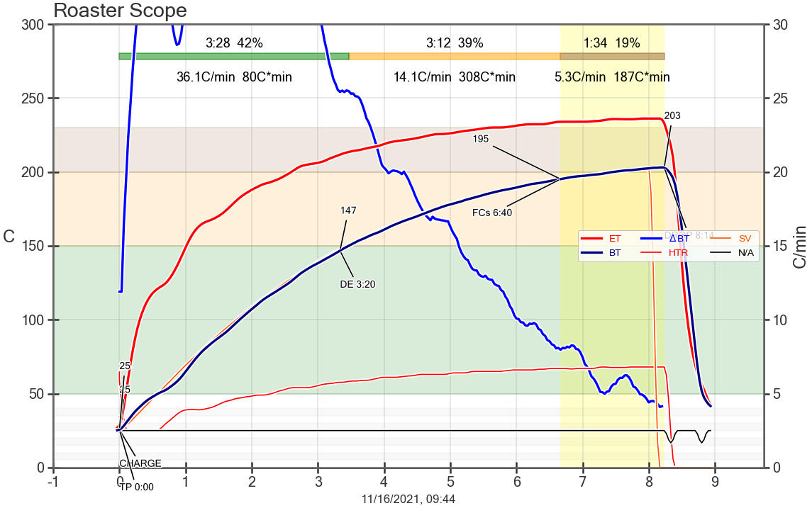
Quote The heater works on D5, no matter how it is defined in user.h (it doesn't matter if D5, or D0, or 14, or 16) Yes, true for slow PWM only. For ICC (CONFIG_PAC2) is used the pin defined in user.h. These are both TC4 legacy code, same behavior there too. Quote ARTISAN automatic steering does not work. Please detail. You means profile following using PID ? Yes, it works, with TC4 PID, not used Artisan PID. Will check what is different in the archives above and come back. Quote It will be difficult for Fluidbed to use the preset roasting philosophy. What you mean ? Using board embedded profiles ? The attached graph is of a roast done today on a FB, following a board profile defined as below: Code Download source int16_t time[50] = { 0, 59, 91, 120, 150, 179, 209, 241, 272, 300, 329, 359, 387, 413, 445, 470, 484, 0 };You can define 9 such custom profiles in board memory, and playback them. The master profile was been designed in Artisan designer, then exported as .csv, to use the data points, picking enough points to describe the profile.
renatoa attached the following image:
Edited by renatoa on 11/16/2021 9:33 AM |
|
|
|
| Will2 |
Posted on 11/16/2021 12:27 PM
|
|
1/4 Pounder Posts: 154 Joined: March 24, 2015 |
Quote renatoa wrote: Please detail. You means profile following using PID ? Yes, it works, with TC4 PID, not used Artisan PID. It doesn't work for me. After the pid;on command, the htr;up command sequence runs inside TC4ESP every 20 seconds, in which case it does not respond to the pid; sv; xxx commands from ARTISAN. It looks like automatic PID tuning is triggered. I have not yet identified the reason for this behavior. Or is there any other way to start ARTISAN mode?   Quote renatoa wrote: What you mean ? Using board embedded profiles?. No, I don't think so. I am thinking, for example, of preheating and that, and in what way it is possible to cancel it. I can't imagine button-operated roasting because they don't work the way you describe them. Edited by Will2 on 11/16/2021 12:34 PM Viliam
|
|
|
|
| renatoa |
Posted on 11/16/2021 1:17 PM
|
|
Administrator Posts: 3104 Joined: September 30, 2016 |
Who sends pid;on command ? Its purpose is to resume an embedded (board) profile following, that was been suspended by a pid;off command. You can't start a roast using pid;on command alone, because counter is not reset to zero. So random values pick from the profile arrays. If no embedded profile is selected, pid;on command has no effect. PID On/off buttons of Artisan and TC4 PID;on/off commands are different things. Please, describe your usage scenario, |
|
|
|
| Will2 |
Posted on 11/16/2021 1:46 PM
|
|
1/4 Pounder Posts: 154 Joined: March 24, 2015 |
It already works, Renato. I think the problem is already solved. ARTISAN: some data on the Modbus ports configuration tab must not be filled in, even if there is another port. Specify 17.11.2021: In the PID window the Slave cell must not be filled as the value 1 Therefore, channels 78 did not work. ie SV, ie PID;SV;xxx. Quote renatoa wrote: ... You can't start a roast using pid;on command alone, because counter is not reset to zero. ... This is not my case, i always have it set event serial command reset at the charge. Edited by Will2 on 11/17/2021 1:11 AM Viliam
|
|
|
|
| renatoa |
Posted on 11/17/2021 1:10 AM
|
|
Administrator Posts: 3104 Joined: September 30, 2016 |
Using board PID and board embedded profile ? I don't mean following a background profile on the Artisan screen, but a profile stored in TC4 board memory. |
|
|
|
| Will2 |
Posted on 11/17/2021 1:24 AM
|
|
1/4 Pounder Posts: 154 Joined: March 24, 2015 |
Quote He hasn't tried this yet. At first I fixed what didn't work. Now I will try to start roasting from a profile stored in TC4ESP. In addition, I'm not sure if the buttons work properly. Or it's not entirely clear to me how the buttons should work. In which part of memory is the profile stored? For TC4, it was remembered on the TC4 board, not in Arduino. For TC4ESP, will it be in a different part of the memory than the recorded sketch? The profile will remain stored in eeprom even if a new sketch is uploaded? Viliam
|
|
|
|
| renatoa |
Posted on 11/17/2021 2:43 AM
|
|
Administrator Posts: 3104 Joined: September 30, 2016 |
The profiles are stored in the 4M EEPROM, on the ESP board. 4096 bytes of this memory is available to the user via programming language. A profile is 400 bytes, thus maximum 9 to store in this memory. They aren't lost when program changes, IF... your Tools/Erase Flash option from Arduino is set to "Sketch Only" (default). A default profile, index 1, is created at memory initialization, you can find the definition of this profile here: https://github.co...Data.h#L76 To create other profile, you change the following below: Code Download source int16_t number = 1; - number, to any 1...9 value, - name, to your desired profile name, only first 20 chars will be shown on LCD - description, to your desired profile desc, only first 40 chars will be shown on LCD - temp, the temperatures array that describe the profile. If you want more points, then you need to change also the time array accordingly. ... and finally... reflash the sketch with the new profile block definition. You can extract a profile data from an Artisan .alog roast file by looking for timex and time2 value lists, en excerpt is shown below: Code Download source 'timex': [0.0499, 2.00732, 4.00739, 6.00743, 8.00754, 10.00763, 12.00863, 14.00871, 16.00874, 18.00891, 20.00899, ... ...extract them into an excel sheet, and decimate to the desired time precision, but maximum 50 values for the entire roast ! This equates to 4 values per minute, every 15 seconds, for a 12 minutes roast. 4*12=48 points, plus an ambient temperature zero time starting point, and a final trailing point with zero values for both time and temp, that mark end of profile. For longer than 12 minutes roasts, you can try 3 points per minute, thus every 20 seconds, allowing 16 minute roasts, or 2 points per minute, thus every 30 seconds, allowing maximum 24 minute roasts. If you want to overwrite an existing profile slot, just change the name, even only one char, for example add a space at the end, if you want to preserve the profile, and change the data only. Edited by renatoa on 11/17/2021 2:49 AM |
|
|
|
| Will2 |
Posted on 11/17/2021 8:18 AM
|
|
1/4 Pounder Posts: 154 Joined: March 24, 2015 |
Before I can work with the profiles stored in eeprom on the tc4ESP board, it must first resolve the button issues. Quote Quote Will2 wrote: ... In addition, I'm not sure if the buttons work properly. Or it's not entirely clear to me how the buttons should work. ... How important is defining Brad buttons in user.h? Did I buy the wrong button board? It is connected to 3.3V. The "UNUSED" button now works as a "MODE " button (for example as a toggle for UP/DOWN buttons target). The "ENTER" key sometimes works the same as the "UP" key. Long press the "DOWN" button at the Fan target to turn off the HTR. (ok, user.h: HTR_CUTOFF_FAN_VAL 20) Short pressing the "DOWN" key does not decrease the values. And the tact in all sorts of ways is impossible to describe. Most likely I'm using the wrong combination of .ino file and libraries. 
Edited by Will2 on 11/17/2021 9:11 AM Viliam
|
|
|
|
| renatoa |
Posted on 11/17/2021 12:31 PM
|
|
Administrator Posts: 3104 Joined: September 30, 2016 |
If the buttons board looks like in the project doc, and board orientation is "portrait" as in photography, i.e. the four buttons cross up, and the "unused" button down, then it should behave ok. 3.3V is ok. If owning a multimeter, you can check the board output voltages, according to: https://github.co...n.cpp#L215 MODE/SETUP is same button, multiple roles/meanings. Could be also CANCEL in some scenarios. Same for ENTER, it has also SELECT meaning. |
|
|
|
| Will2 |
Posted on 11/17/2021 1:57 PM
|
|
1/4 Pounder Posts: 154 Joined: March 24, 2015 |
Thank you Renato, I'm glad an explanation was found. This means that the same boards with different resistance ladders are sold. voltage values should be: 0 = UP, 0.45V = Enter, 1V = Settings, 1.6V = DOWN my resistance ladder generates voltage values: 0 = UP, 0.10V = Enter, 0.28V = Settings, 0.53V = DOWN, 1.10v Unused, 3.0V Unpressed  Surely the best way would be to have the resistance values of a ladder that works measured. Will it be possible? Viliam
|
|
|
|
| renatoa |
Posted on 11/17/2021 2:38 PM
|
|
Administrator Posts: 3104 Joined: September 30, 2016 |
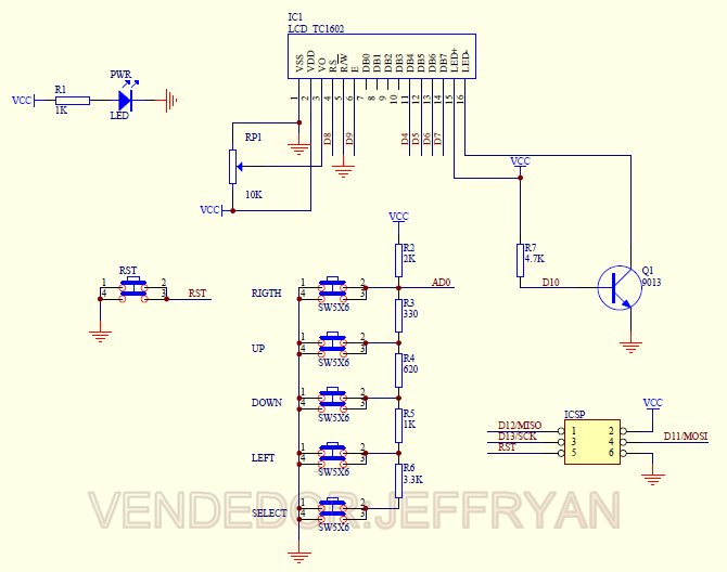
Great find ! The values are (somewhat) public... because they are copied by chinese from the Adafruit LCD/buttons shield, whose schematic is attached. The only difference you should be aware is that my code is for board above rotated 90 degrees clockwise. So the buttons from the schematic and picture above have other meanings: LEFT - is UP for me UP - is ENTER/SELECT DOWN - is MODE/SETUP RIGHT - is DOWN rightmost SW5 - SELECT in the schematic - is the unused button
renatoa attached the following image:
|
|
|
|

| Jump to Forum: |
Powered by PHP-Fusion Copyright © 2024 PHP-Fusion Inc
Released as free software without warranties under GNU Affero GPL v3
Designed with ♥ by NetriXHosted by skpacman