Login
Shoutbox
You must login to post a message.
renatoa
07/26/2024 3:49 PM
Bill grubbe and Jk, 

allenb
07/26/2024 5:15 AM
Spiderkw Welcome to HRO!


renatoa
07/24/2024 8:31 AM
ramiroflores and John123,

 ?
?

 ?
?renatoa
07/21/2024 1:18 AM
 , Luislobo
renatoa
07/19/2024 11:28 AM
Koepea, 

Forum Threads
Newest Threads
Skywalker roaster modsBackground Roast Iss...
Hello from Arkansas
TC4ESP
Green coffee reviews
Hottest Threads
| Skywalker roaster... | [375] |
| TC4ESP | [115] |
| War on Farmers by... | [47] |
| Adventures in flu... | [26] |
| Hello! (soon) Roa... | [17] |
Donations
Latest Donations
dmccallum - 10.00
JackH - 25.00
snwcmpr - 10.00
Anonymous - 2.00
Anonymous - 5.00
dmccallum - 10.00
JackH - 25.00
snwcmpr - 10.00
Anonymous - 2.00
Anonymous - 5.00
Users Online
Guests Online: 10
Members Online: 0
Total Members: 8,393
Newest Member: Bill grubbe
Members Online: 0
Total Members: 8,393
Newest Member: Bill grubbe
View Thread
Who is here? 1 guest(s)
|
TC4ESP
|
|
| renatoa |
Posted on 11/17/2021 2:43 AM
|
|
Administrator  Posts: 3104 Joined: September 30, 2016 |
The profiles are stored in the 4M EEPROM, on the ESP board. 4096 bytes of this memory is available to the user via programming language. A profile is 400 bytes, thus maximum 9 to store in this memory. They aren't lost when program changes, IF... your Tools/Erase Flash option from Arduino is set to "Sketch Only" (default). A default profile, index 1, is created at memory initialization, you can find the definition of this profile here: https://github.co...Data.h#L76 To create other profile, you change the following below: Code Download source int16_t number = 1; - number, to any 1...9 value, - name, to your desired profile name, only first 20 chars will be shown on LCD - description, to your desired profile desc, only first 40 chars will be shown on LCD - temp, the temperatures array that describe the profile. If you want more points, then you need to change also the time array accordingly. ... and finally... reflash the sketch with the new profile block definition. You can extract a profile data from an Artisan .alog roast file by looking for timex and time2 value lists, en excerpt is shown below: Code Download source 'timex': [0.0499, 2.00732, 4.00739, 6.00743, 8.00754, 10.00763, 12.00863, 14.00871, 16.00874, 18.00891, 20.00899, ... ...extract them into an excel sheet, and decimate to the desired time precision, but maximum 50 values for the entire roast ! This equates to 4 values per minute, every 15 seconds, for a 12 minutes roast. 4*12=48 points, plus an ambient temperature zero time starting point, and a final trailing point with zero values for both time and temp, that mark end of profile. For longer than 12 minutes roasts, you can try 3 points per minute, thus every 20 seconds, allowing 16 minute roasts, or 2 points per minute, thus every 30 seconds, allowing maximum 24 minute roasts. If you want to overwrite an existing profile slot, just change the name, even only one char, for example add a space at the end, if you want to preserve the profile, and change the data only. Edited by renatoa on 11/17/2021 2:49 AM |
|
|
|
| Will2 |
Posted on 11/17/2021 8:18 AM
|
|
1/4 Pounder  Posts: 154 Joined: March 24, 2015 |
Before I can work with the profiles stored in eeprom on the tc4ESP board, it must first resolve the button issues. Quote Quote Will2 wrote: ... In addition, I'm not sure if the buttons work properly. Or it's not entirely clear to me how the buttons should work. ... How important is defining Brad buttons in user.h? Did I buy the wrong button board? It is connected to 3.3V. The "UNUSED" button now works as a "MODE " button (for example as a toggle for UP/DOWN buttons target). The "ENTER" key sometimes works the same as the "UP" key. Long press the "DOWN" button at the Fan target to turn off the HTR. (ok, user.h: HTR_CUTOFF_FAN_VAL 20) Short pressing the "DOWN" key does not decrease the values. And the tact in all sorts of ways is impossible to describe. Most likely I'm using the wrong combination of .ino file and libraries. 
Edited by Will2 on 11/17/2021 9:11 AM Viliam
|
|
|
|
| renatoa |
Posted on 11/17/2021 12:31 PM
|
|
Administrator  Posts: 3104 Joined: September 30, 2016 |
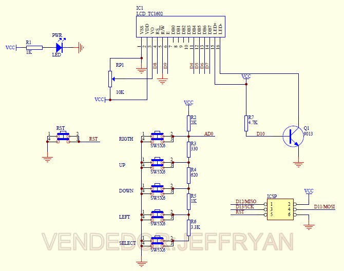
If the buttons board looks like in the project doc, and board orientation is "portrait" as in photography, i.e. the four buttons cross up, and the "unused" button down, then it should behave ok. 3.3V is ok. If owning a multimeter, you can check the board output voltages, according to: https://github.co...n.cpp#L215 MODE/SETUP is same button, multiple roles/meanings. Could be also CANCEL in some scenarios. Same for ENTER, it has also SELECT meaning. |
|
|
|
| Will2 |
Posted on 11/17/2021 1:57 PM
|
|
1/4 Pounder  Posts: 154 Joined: March 24, 2015 |
Thank you Renato, I'm glad an explanation was found. This means that the same boards with different resistance ladders are sold. voltage values should be: 0 = UP, 0.45V = Enter, 1V = Settings, 1.6V = DOWN my resistance ladder generates voltage values: 0 = UP, 0.10V = Enter, 0.28V = Settings, 0.53V = DOWN, 1.10v Unused, 3.0V Unpressed  Surely the best way would be to have the resistance values of a ladder that works measured. Will it be possible? Viliam
|
|
|
|
| renatoa |
Posted on 11/17/2021 2:38 PM
|
|
Administrator  Posts: 3104 Joined: September 30, 2016 |
Great find ! The values are (somewhat) public... because they are copied by chinese from the Adafruit LCD/buttons shield, whose schematic is attached. The only difference you should be aware is that my code is for board above rotated 90 degrees clockwise. So the buttons from the schematic and picture above have other meanings: LEFT - is UP for me UP - is ENTER/SELECT DOWN - is MODE/SETUP RIGHT - is DOWN rightmost SW5 - SELECT in the schematic - is the unused button
renatoa attached the following image:
|
|
|
|
| Will2 |
Posted on 11/17/2021 3:35 PM
|
|
1/4 Pounder  Posts: 154 Joined: March 24, 2015 |
Renato You were faster, I just measured the resistances on my board and drew a diagram. 3k3, 1k, 1020, 330, they agree. instead of 2k i have 10k, so just replace 1 resistor and it will work. Viliam
|
|
|
|
| renatoa |
Posted on 11/18/2021 3:32 AM
|
|
Administrator  Posts: 3104 Joined: September 30, 2016 |
Yes, this was my guess too, your values are ok as proportions, just scaled down due to that wrong pull-up resistor. One change fix all ! Meanwhile, thinking more about this orientation confusion, did some quick additions to the buttons library, and now it can be used in both landscape and portrait mode ! Not posted yet, to not amplify the versions mess, if you want I can post here for you to test. |
|
|
|
| Will2 |
Posted on 11/19/2021 8:00 AM
|
|
1/4 Pounder  Posts: 154 Joined: March 24, 2015 |
Quote renatoa wrote: ... if you want I can post here for you to test. I'd rather use the landscape button mode, you can post here, or send me an e-mail. Yesterday I added another pull-up resistor 2k5, so together it's 2k, the buttons now work normally. Today I bought a SMD 0805 2k, so I will exchange a 10k resistor for 2k. Viliam
|
|
|
|
| renatoa |
Posted on 11/19/2021 8:37 AM
|
|
Administrator  Posts: 3104 Joined: September 30, 2016 |
Attached... You just have to un-comment the // #define LANDSCAPE at line 196 in adcButton.cpp ...
renatoa attached the following file:
|
|
|
|
| Will2 |
Posted on 11/19/2021 12:50 PM
|
|
1/4 Pounder  Posts: 154 Joined: March 24, 2015 |
Quote renatoa wrote: ... because they are copied by chinese from the Adafruit ... But the Chinese probably don't care if he puts 2001 or 1002 there: 
Viliam
|
|
|
|
| renatoa |
Posted on 11/19/2021 1:06 PM
|
|
Administrator  Posts: 3104 Joined: September 30, 2016 |
Lol  |
|
|
|
| CamMor89 |
Posted on 12/22/2021 6:03 AM
|
|
Newbie  Posts: 10 Joined: April 06, 2021 |
Hi Renatoa. Is it possible to use max31865 (pt100 tc)? I can't seem to find any AD8495, and I already have 3x max31865 laying around (from when I tried to make a esp32 controller). |
|
|
|
| renatoa |
Posted on 12/23/2021 7:16 AM
|
|
Administrator  Posts: 3104 Joined: September 30, 2016 |
Yes, I am aware about the issue, until April they seems gone, unobtainium at any price... You have the choice to disable their usage though, and use the MCP3424 ADC standalone, as in the classic TC4. The changes required are the following: - first disable TC amp usage here: https://github.co...cADC.h#L64 - then choose your TC type here, K or whatever: https://github.co...uple.h#L58 ... and don't forget to disable Pt sensor usage - and finally, update the thermocouple variables here: https://github.co...user.h#L68 and here... https://github.co...D.ino#L302 Regarding using max31865 or MAX31856, that was been previously discussed here in this thread, there is a hardware limitation: not enough pins. They both are using SPI, whose pins are already busy with I2C of LCD display, so is a matter of ... or-or, exclusive, display or SPI sensor(s) If you agree using the setup without UI, then I can add the MAX chips library somewhere after holidays. There is a third choice though... using TL amp board for Pt sensors, with analog output and the current ADC. This is a new feature added to TC4ESP, announced some months ago, in the first page of the thread. Not sure if you are familiar with these amp boards, they are widely used in 3d printing, this model: https://www.go-3d...d-printer/ |
|
|
|
| trisse |
Posted on 06/01/2024 2:36 PM
|
|
Newbie  Posts: 21 Joined: November 01, 2020 |
Is this project still alive? Thinking order the components for modding my Ali fluidbed roaster |
|
|
|
| renatoa |
Posted on 06/02/2024 2:19 AM
|
|
Administrator  Posts: 3104 Joined: September 30, 2016 |
Yes and no  The github version is a good start and it's working But my working copy evolved so much... that became unstable. I have some stable intermediate copies though... I can assist you with all you need anyway. Also, an accident, last year, due to powering with 5V instead 3.3V destroyed all my modules stock, and also a lot of confidence in mine... :( so frozen it in an unknown state. Roasting full manual since then, with a variator and Mastech meter. Also, as a sidenote, consider that the last versions were redesigned to use the full range of MAX chips, instead the patriarch MC3424 ADC that define the TC4 architecture. This paradigm change allows you to use even Pt sensors instead TC, a feature that many considered unrivaled, atm when I did it. |
|
|
|
| trisse |
Posted on 06/02/2024 9:55 AM
|
|
Newbie  Posts: 21 Joined: November 01, 2020 |
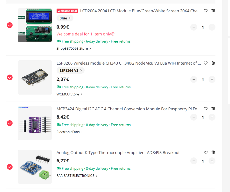
Quote renatoa wrote: Yes and no  The github version is a good start and it's working But my working copy evolved so much... that became unstable. I have some stable intermediate copies though... I can assist you with all you need anyway. Also, an accident, last year, due to powering with 5V instead 3.3V destroyed all my modules stock, and also a lot of confidence in mine... :( so frozen it in an unknown state. Roasting full manual since then, with a variator and Mastech meter. Also, as a sidenote, consider that the last versions were redesigned to use the full range of MAX chips, instead the patriarch MC3424 ADC that define the TC4 architecture. This paradigm change allows you to use even Pt sensors instead TC, a feature that many considered unrivaled, atm when I did it. Sounds Good. Found most of the components on ali so will make a order there. Tho i got some stuff over from a Gaggiuno Lego build. You said it will work with most MAX chips now, does that include MAX6675? This should be enough to get me started right? Already got a Fotek SSR 40A, also got a robotdyn 4A-400V dimmer that i dont use but it will not take my heater
trisse attached the following image:
Edited by trisse on 06/02/2024 10:55 AM |
|
|
|
| renatoa |
Posted on 06/02/2024 1:06 PM
|
|
Administrator  Posts: 3104 Joined: September 30, 2016 |
Yes, it does include MAX6675, but provided just as the little brother of the family, i.e. the cheapest solution, without having expectations about the precision. If you go on MAX path, any MAX, then the list above changes a lot... the last two positions removed, and two MAX boards added, with the schematic changed accordingly. Contact me via PM for this case, to sketch together the new schematic and provide new code. |
|
|
|
| trisse |
Posted on 06/02/2024 1:50 PM
|
|
Newbie  Posts: 21 Joined: November 01, 2020 |
Hmm ok so the precision would be lower with the MAX boards then your BOM alternative? What would you recommend? Maybe some other MAX board? Type k thermocouple would be enough, at least to start with as I have a lot of those laying around. Maybe go down the pt100 path later |
|
|
|
| renatoa |
Posted on 06/03/2024 1:43 AM
|
|
Administrator  Posts: 3104 Joined: September 30, 2016 |
MAX6675/31855 have 0.25C resolution, which is not enough to accurately reproduce an average 10C/minute RoR slope, which equates to 0.167C per second rate of change. All the others solutions are in other league, with resolutions in a hundredth of C degree range. MAX31856 for example has 0.0078125°C resolution, obviously much more that is needed in many industries... but they made it... because they can  Original TC4, and my variation using TC amps, are both close to MAX31856. |
|
|
|
| trisse |
Posted on 06/03/2024 10:42 AM
|
|
Newbie  Posts: 21 Joined: November 01, 2020 |
Quote renatoa wrote: MAX6675/31855 have 0.25C resolution, which is not enough to accurately reproduce an average 10C/minute RoR slope, which equates to 0.167C per second rate of change. All the others solutions are in other league, with resolutions in a hundredth of C degree range. MAX31856 for example has 0.0078125°C resolution, obviously much more that is needed in many industries... but they made it... because they can  Original TC4, and my variation using TC amps, are both close to MAX31856. Thx, ordered according to your BOM. Now for the waiting... |
|
|
|
| tam |
Posted on 06/19/2024 2:16 AM
|
|
Newbie  Posts: 3 Joined: June 19, 2024 |
I am a novice with arduino-ide but managed to compile and upload a blink sketch to my esp8266 using Debian 11 and arduino-ide_2.2.1_Linux_64bit. Placed contents of TC4-shield-master/applications/Artisan/aArtisanESP/tags/REL_aArtisanESP_1_0/aArtisanESP.zip into my sketchbook folder and get these errors trying to compile aArtisanESP.ino: /home/tam/Arduino/aArtisanESP/cmndreader.cpp: In member function 'virtual boolean unitsCmnd::doCommand(CmndParser*)': /home/tam/Arduino/aArtisanESP/cmndreader.cpp:495:1: error: control reaches end of non-void function [-Werror=return-type] 495 | } | ^ /home/tam/Arduino/aArtisanESP/cmndreader.cpp: In member function 'virtual boolean pidCmnd::doCommand(CmndParser*)': /home/tam/Arduino/aArtisanESP/cmndreader.cpp:651:1: error: control reaches end of non-void function [-Werror=return-type] 651 | } | ^ cc1plus: some warnings being treated as errors exit status 1 Compilation error: control reaches end of non-void function [-Werror=return-type] Can anyone help with this? Thanks |
|
|
|
| renatoa |
Posted on 06/19/2024 5:21 AM
|
|
Administrator  Posts: 3104 Joined: September 30, 2016 |
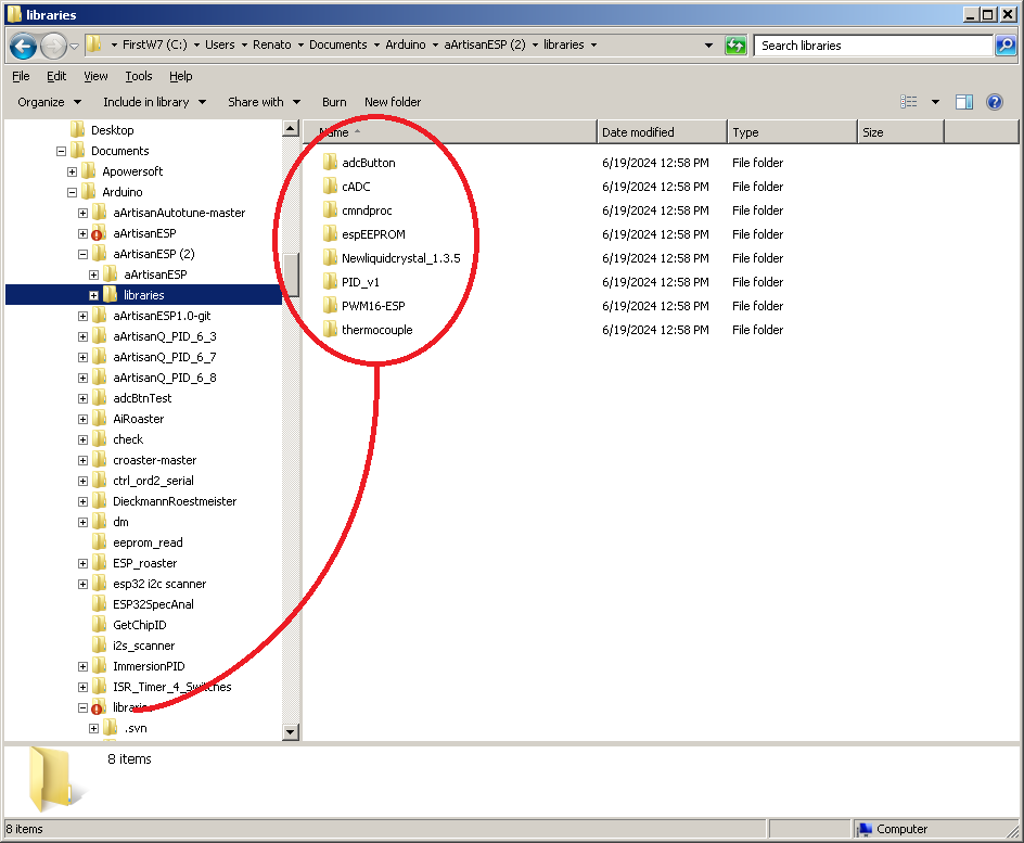
Just checked, and I hate when I have to say this, but... it worked for me Did you copied the content of libraries folder from archive to libraries folder of Arduino ? As I sketched in attached screen ...
renatoa attached the following image:
|
|
|
|
| tam |
Posted on 06/19/2024 7:37 AM
|
|
Newbie  Posts: 3 Joined: June 19, 2024 |
Thanks for responding, I have copied the archive library folder contents to my sketchbook folder: ls Arduino/libraries/ adcButton cmndproc Newliquidcrystal_1.3.5 PWM16-ESP cADC espEEPROM PID_v1 thermocouple ls Arduino/aArtisanESP/ aArtisanESP.ino cmndreader.h espProfiles.ino phase_ctrl.h aArtisanQ_PID.ino ESP8266 libESP.h SGfilters.ino cmndreader.cpp espData.h phase_ctrl.cpp user.h Also inside arduino-ide gui under Sketch>include_libraries> I see them as available. |
|
|
|
| tam |
Posted on 06/20/2024 11:33 AM
|
|
Newbie  Posts: 3 Joined: June 19, 2024 |
Fixed by downgrading my esp8266 arduino core to version 3.0. |
|
|
|
| renatoa |
Posted on 06/21/2024 7:20 AM
|
|
Administrator  Posts: 3104 Joined: September 30, 2016 |
Ah... this explains a lot... project is 5 years old, code written for 2.x core. Added this requirement to the first post. Also github Instructions file updated. |
|
|
|
| Jump to Forum: |
Powered by PHP-Fusion Copyright © 2024 PHP-Fusion Inc
Released as free software without warranties under GNU Affero GPL v3
Designed with ♥ by NetriXHosted by skpacman


