
Login

Shoutbox
You must login to post a message.
renatoa
07/26/2024 3:49 PM
Bill grubbe and Jk, 
allenb
07/26/2024 5:15 AM
Spiderkw Welcome to HRO!

renatoa
07/24/2024 8:31 AM
ramiroflores and John123,

 ?
?
?renatoa
07/21/2024 1:18 AM
 , Luislobo
renatoa
07/19/2024 11:28 AM
Koepea,
Forum Threads
Newest Threads
Skywalker roaster modsBackground Roast Iss...
Hello from Arkansas
TC4ESP
Green coffee reviews
Hottest Threads
| Skywalker roaster... | [375] |
| TC4ESP | [115] |
| War on Farmers by... | [47] |
| Adventures in flu... | [26] |
| Hello! (soon) Roa... | [17] |
In Memory Of Ginny

Donations
Latest Donations
dmccallum - 10.00
JackH - 25.00
snwcmpr - 10.00
Anonymous - 2.00
Anonymous - 5.00
dmccallum - 10.00
JackH - 25.00
snwcmpr - 10.00
Anonymous - 2.00
Anonymous - 5.00
Users Online
Guests Online: 4
Members Online: 0
Total Members: 8,393
Newest Member: Bill grubbe
Members Online: 0
Total Members: 8,393
Newest Member: Bill grubbe
View Thread
Who is here? 2 guest(s)
 Fluid Bed Roaster Build - bye bye Heat Gun and Flour Sifter
|
|
| jbrux4 |
Posted on 11/11/2019 7:39 PM
|
|
1/4 Pounder  Posts: 139 Joined: October 26, 2019 |
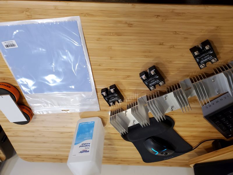
Build Episode 1: SSR and Heatsink Assembly *also attached in the .7z file Disclaimer: This is how I did it. You don?t have to do it this way. If I have done something detrimental to the safety of myself or others, please let me know. Discussion: I will be utilizing 3 different 110V circuits for the elements and blower, and I will have my two heating elements wired in parallel. It is better to have SSRs with heat sinks to prevent overheating and to achieve specifications as stated by the manufacturer. Goal(s):
Materials & Tools:
Process:
Links to things:
jbrux4 attached the following file:
jbrux4 attached the following images:

Edited by jbrux4 on 11/11/2019 9:46 PM R/
Jared |
|
|
|
| jbrux4 |
Posted on 11/13/2019 2:20 PM
|
|
1/4 Pounder Posts: 139 Joined: October 26, 2019 |
Quote jbrux4 wrote: Questions Regarding HONEYCOMB AIRFLOW STRAIGHTENER: For those who have the know-how with the honeycomb airflow straightener:
From what I have gathered from a NASA paper on an MAF straightener, it is best to have the strightener as far down the tunnel/tube as possible prior to its purposeful use. My own intuition tells me that the turbulence of the air while passing the heating elements is good because this means it gets heated for longer. Whether there is a measurable impact - don't know, but the diagrams and drawings I reviewed suggest it. As for the replacement of a perf plate or screen, I don't quite know yet because I don't know the sizes of the openings of the honeycomb, but I suspect those openings are too large and a perf plate or mesh scree is necessary. I am pretty sure I can use a few different tools to snip away at the honeycomb or even power cut - depends on the rigidity of the stuff - it is aluminum. I also read in the NASA paper that damage to the honeycomb has significant ramifications in terms of performance, so I want to handle it carefully. R/
Jared |
|
|
|
| jbrux4 |
Posted on 11/13/2019 2:31 PM
|
|
1/4 Pounder Posts: 139 Joined: October 26, 2019 |
I am still waiting on some pieces and parts. I did get notification of a package from the Australian Post, so I should have the TC4 and ZCD. I learned how to crimp those DuPont connectors last night, but I am still waiting on the housings. I need to practice with the soldering iron - it's been 8 years since I did any soldering for my home brew and wood working stuff. I ran into an issue with the Flow-Thru Motor Housing I am devising, so I had to return a couple pieces and I am waiting on replacement parts. I am in contact with a couple vendors regarding the roast chamber and high temp gaskets. The cyclone is on its way from China. When I get a set of pieces to make a logical build episode, I will. Thanks to everybody for info, whether directly or indirectly from past threads and posts. It all helps. R/
Jared |
|
|
|
| allenb |
Posted on 11/13/2019 4:57 PM
|
 Administrator Posts: 3869 Joined: February 23, 2010 |
Youre moving along at a rapid pace! This is the Christmas morning phase when all the parts start arriving and can't wait to see it all come together. Keep us posted
1/2 lb and 1 lb drum, Siemens Sirocco fluidbed, presspot, chemex, cajun biggin brewer from the backwoods of Louisiana
|
|
|
|
| jbrux4 |
Posted on 11/13/2019 9:05 PM
|
|
1/4 Pounder Posts: 139 Joined: October 26, 2019 |
Quote allenb wrote: Youre moving along at a rapid pace! This is the Christmas morning phase when all the parts start arriving and can't wait to see it all come together. Keep us posted I am moving fast. My wife and kids have raised a couple eyebrows so far, but they know exactly where to put the strange looking things that come in. R/
Jared |
|
|
|
| jbrux4 |
Posted on 11/18/2019 2:27 PM
|
|
1/4 Pounder Posts: 139 Joined: October 26, 2019 |
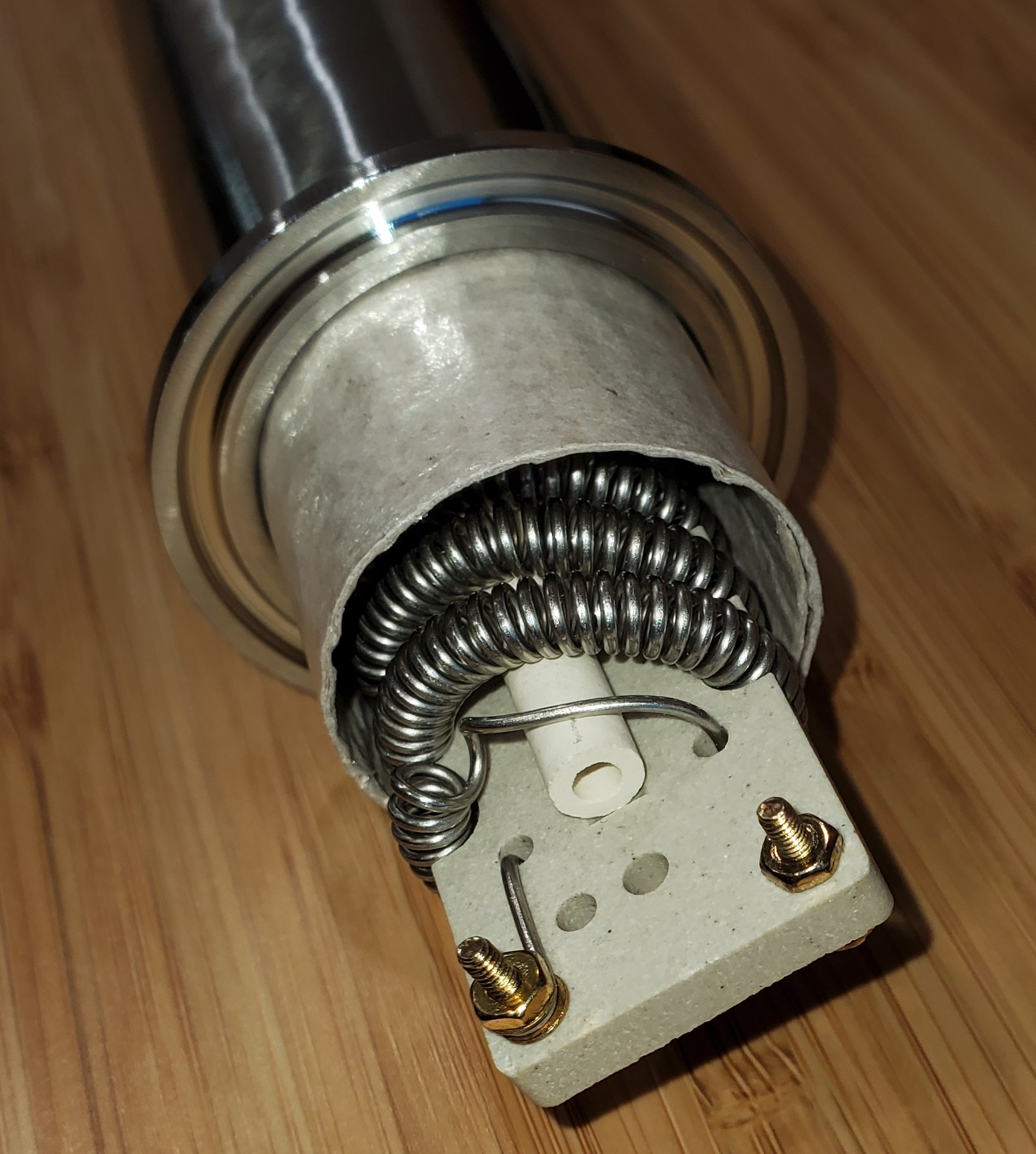
QUESTION: FLEXIBLE MICA I am using a 1.5" stainless steel heat pipe which will have two heating elements in line. the elements will have less that 1/4" around the circumference. The ID of the pipe will have flexible mica as a sleeve. This mica will reduce the amoutn around the circumference of the element. Is this safe? What if the element physically touches the mica? Is there a chance of burn through of the mica leading to electrical shock? The mica is .020, rated to 930F, and 508v/mil: https://www.mcmas...m/85825k45 Thanks in advance.
jbrux4 attached the following image:
Edited by jbrux4 on 11/18/2019 7:34 PM R/
Jared |
|
|
|
| jbrux4 |
Posted on 11/21/2019 2:56 PM
|
|
1/4 Pounder Posts: 139 Joined: October 26, 2019 |
Quote jbrux4 wrote: QUESTION: FLEXIBLE MICA I am using a 1.5" stainless steel heat pipe which will have two heating elements in line. the elements will have less that 1/4" around the circumference. The ID of the pipe will have flexible mica as a sleeve. This mica will reduce the amoutn around the circumference of the element. Is this safe? What if the element physically touches the mica? Is there a chance of burn through of the mica leading to electrical shock? The mica is .020, rated to 930F, and 508v/mil: https://www.mcmas...m/85825k45 Thanks in advance. From the non response - I am guessing I asked a self-evident question considering the specs of the mica. The self-evident answer is "of course it will work." Still waiting on some parts and pieces, and I still haven't found a suitable solution for the blower motor housing. I will keep searching. R/
Jared |
|
|
|
| allenb |
Posted on 11/21/2019 5:13 PM
|
|
Administrator Posts: 3869 Joined: February 23, 2010 |
Quote Is this safe? What if the element physically touches the mica? Is there a chance of burn through of the mica leading to electrical shock? Probably not a chance for burn through unless you lose air flow and nichrome turns to whitish yellow just before melting down. In that case, as long as the tube is well grounded, you'll pop the circuit breaker if the breaker is in good shape. Although it's theoretically safe, it's not in meeting best practice standards since this usually doesn't afford optimum air flow past all areas of the element since some of the coil turns will be touching the mica surface and those areas of the element will be to some degree hotter than the rest. Its best to use some form of stand-off to center the element. What I usually do is take a piece of mica board and cut a notch in it to allow sliding it snugly over the ends which forms a sort of "T" arrangement and keeps the element centered within the tube. 1/2 lb and 1 lb drum, Siemens Sirocco fluidbed, presspot, chemex, cajun biggin brewer from the backwoods of Louisiana
|
|
|
|
| jbrux4 |
Posted on 11/22/2019 7:46 AM
|
|
1/4 Pounder Posts: 139 Joined: October 26, 2019 |
Quote allenb wrote: Quote Is this safe? What if the element physically touches the mica? Is there a chance of burn through of the mica leading to electrical shock? Probably not a chance for burn through unless you lose air flow and nichrome turns to whitish yellow just before melting down. In that case, as long as the tube is well grounded, you'll pop the circuit breaker if the breaker is in good shape. Although it's theoretically safe, it's not in meeting best practice standards since this usually doesn't afford optimum air flow past all areas of the element since some of the coil turns will be touching the mica surface and those areas of the element will be to some degree hotter than the rest. Its best to use some form of stand-off to center the element. What I usually do is take a piece of mica board and cut a notch in it to allow sliding it snugly over the ends which forms a sort of "T" arrangement and keeps the element centered within the tube. Understood allenb. I was planning on setting it in the center, but with the airflow causing possible vibration/movement over time, the possibility for the nichrome to touch the mica exists. However, since I have the ability to put this together and to take apart in pieces, I can monitor this when performing cleaning. I can also slide the mica out and look at the surface for any marks or burns. Thanks for the tip on how you have done this. R/
Jared |
|
|
|
| jbrux4 |
Posted on 11/24/2019 11:00 AM
|
|
1/4 Pounder Posts: 139 Joined: October 26, 2019 |
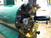
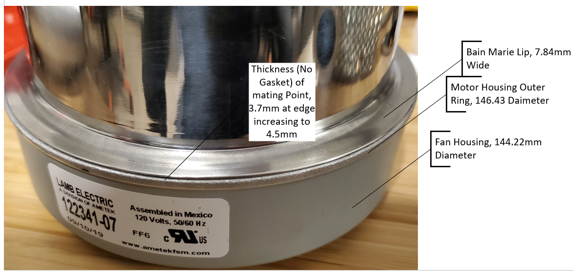
Question: Unique Coupling Required - Any Examples of Proven Methods for My Use Case? The picture shows a flow through vacuum/blower with a Bain-Marie pot covering the motor. The unique compression needed is pressure around the circumference and top down to press the lid against the blower housing. The possibility exists to add a gasket between the two pieces which would add to the thickness dimension below. Dimensions: Fan Housing Diameter: 144.22mm, 5.678" Motor Housing Outer Ring: 146.43, 5.765" Bain Marie Lip: 7.84mm, .309" Motor Outer Ring and Bain Marie Lip Thickness: 3.7mm to 4.5mm, 0.146" to 0.177"
jbrux4 attached the following image:
R/
Jared |
|
|
|
| CK |
Posted on 11/25/2019 11:06 AM
|
|
1/2 Pounder  Posts: 252 Joined: December 07, 2018 |
Post 98 on the transparent roaster link shows a design that works to house any number of blower styles. I've used this design to house 3 different blowers already... only with slight modification to the original 2 part setup. In your case, you most likely would have a top and bottom board, with a top and bottom clamshell part respectively, both wood halves could be held together with threaded rod external to the plastic blower housing. |
|
|
|
| CK |
Posted on 11/27/2019 10:36 AM
|
|
1/2 Pounder Posts: 252 Joined: December 07, 2018 |
An example of how flow-through motors can be housed.
CK attached the following images:


|
|
|
|
| jbrux4 |
Posted on 11/28/2019 1:08 PM
|
|
1/4 Pounder Posts: 139 Joined: October 26, 2019 |
Quote Great example CK. There is a black covering over the fan housing (see pic for callout). I am wondering what it is, where you got it from, and its purpose. Mine doesn't have that.
jbrux4 attached the following image:

R/
Jared |
|
|
|
| CK |
Posted on 11/28/2019 1:18 PM
|
|
1/2 Pounder Posts: 252 Joined: December 07, 2018 |
That is the rubber mount that that mated to the plastic housing of the hand-held stick vacuum it came from... vibration dampening for the whole unit. For your application, you could probably get away with compressing any other suitable damping material under your motor for vibration and sound reduction. |
|
|
|
| jbrux4 |
Posted on 12/08/2019 11:47 AM
|
|
1/4 Pounder Posts: 139 Joined: October 26, 2019 |
You can see the potential heat Pipe Design in the attached pic. The one thing I am still up in the air about is whether to switch the mass airflow straightener and the thermocouple. Any comments on the placement? I am currently on the hunt for someone with a drill press so I can get those holes drilled. Needing some of those holes tapped as well. I also received my Sight Glass a.k.a. Roast Chamber, but was broke in shipment. A replacement is on the way. It was horrible to see it broken upon opening. But hey, I will have a couple of extra Sight Flanges, so I can't complain too much. The borosilicate glass is 9mm thick on this thing. I was going to replace the glass with a taller one, but I think I am going to keep it stock and just extend upwards with a 4" spool.  The TC4/Arduino connection with Artisan works. Big thanks to Greencardigan for the TC4 and all the information provided. I did plug in the thermocouples to see the real-time temp in Artisan. I connected & created the controls and sliders as prescribed in https://forum.hom...ad_id=5393. I didn't modify the user.h because I was just establishing the connection and just getting accustomed to loading the sketches onto the Arduino, etc. I bought some dupont housings on ebay - but am waiting and waiting for delivery. Once I get those, I can start making all the wires for connections to the TC4. I prob should have bought pre-made ones, but I wanted the full immersion experience I guess. Anyways, I am looking forward to progressing further and providing actual build episodes because that means I will be getting closer to roasting/testing with this thing.
jbrux4 attached the following images:
R/
Jared |
|
|
|
| jbrux4 |
Posted on 12/15/2019 1:03 PM
|
|
1/4 Pounder Posts: 139 Joined: October 26, 2019 |
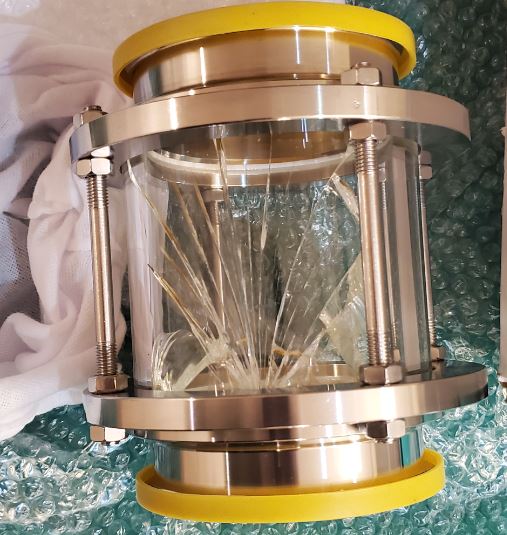
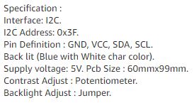
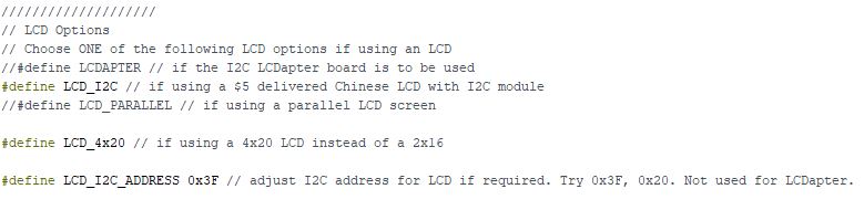
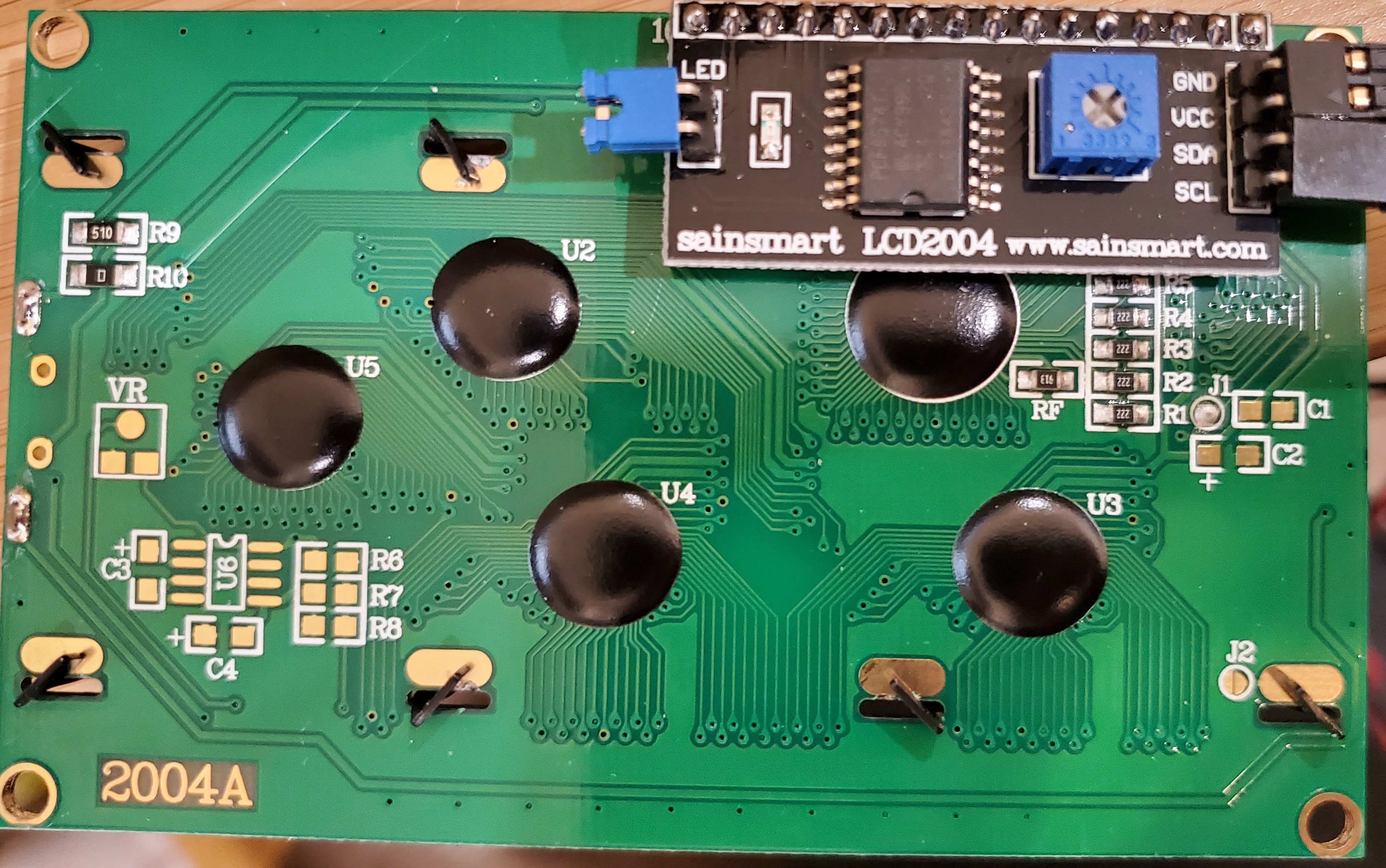
ISSUE: LCD is not showing info. I am currently wiring from TC4 to components. I am hung up on the LCD at the moment. The pics show the LCD output, the user.h address and the manufacturer address. I loaded the sketch into Arduino with the modified LCD address. (note: I learned that I must remove the TC4 shield to upload an updated sketch). I have Artisan up and running and connected to the TC4 (temp readings are real-time and accurate). Any ideas on how to determine and remedy the issue?
jbrux4 attached the following images:

Edited by jbrux4 on 12/15/2019 1:14 PM R/
Jared |
|
|
|
| renatoa |
Posted on 12/15/2019 1:19 PM
|
|
Administrator Posts: 3104 Joined: September 30, 2016 |
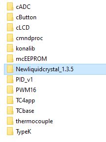
First, play with contrast pot. If no success, try Newliquidcrystal_1.3.5 library instead, was the one I had success with a new generation 4x20, seems the i2c chip is different now. |
|
|
|
| jbrux4 |
Posted on 12/15/2019 1:24 PM
|
|
1/4 Pounder Posts: 139 Joined: October 26, 2019 |
Quote renatoa wrote: First, play with contrast pot. If no success, try Newliquidcrystal_1.3.5 library instead, was the one I had success with a new generation 4x20, seems the i2c chip is different now. Thanks for the tips. The contrast pot did not fix. The new library.....ummm - getting into unfamiliar territor - but I will check it out. The library is available from github? R/
Jared |
|
|
|
| JackH |
Posted on 12/15/2019 1:27 PM
|
 Administrator Posts: 1809 Joined: May 10, 2011 |
The LCD in his photo does not look like a 4X20 to me.
---Jack
KKTO Roaster. |
|
|
|
| jbrux4 |
Posted on 12/15/2019 1:29 PM
|
|
1/4 Pounder Posts: 139 Joined: October 26, 2019 |
Quote jbrux4 wrote: Quote renatoa wrote: First, play with contrast pot. If no success, try Newliquidcrystal_1.3.5 library instead, was the one I had success with a new generation 4x20, seems the i2c chip is different now. Thanks for the tips. The contrast pot did not fix. The new library.....ummm - getting into unfamiliar territor - but I will check it out. The library is available from github? The NewLiquidcrystal_1.3.5 is the library being used. I attached the code from the aArtisanQ_PID if it helps.
jbrux4 attached the following images:

Edited by jbrux4 on 12/15/2019 1:36 PM R/
Jared |
|
|
|
| jbrux4 |
Posted on 12/15/2019 1:39 PM
|
|
1/4 Pounder Posts: 139 Joined: October 26, 2019 |
Quote Please see the link for what I have: https://www.amazo...&psc=1 I also enhanced the contrast and attached the pic.
jbrux4 attached the following image:

Edited by jbrux4 on 12/15/2019 1:48 PM R/
Jared |
|
|
|
| JackH |
Posted on 12/15/2019 1:49 PM
|
|
Administrator Posts: 1809 Joined: May 10, 2011 |
Quote renatoa wrote: First, play with contrast pot. If no success, try Newliquidcrystal_1.3.5 library instead, was the one I had success with a new generation 4x20, seems the i2c chip is different now. should have quoted. ---Jack
KKTO Roaster. |
|
|
|
| jbrux4 |
Posted on 12/15/2019 1:57 PM
|
|
1/4 Pounder Posts: 139 Joined: October 26, 2019 |
Quote JackH wrote: Quote renatoa wrote: First, play with contrast pot. If no success, try Newliquidcrystal_1.3.5 library instead, was the one I had success with a new generation 4x20, seems the i2c chip is different now. should have quoted. No worries - just want to make sure it is understood what I have. I appreciate your attention and any assistance you may provide. R/
Jared |
|
|
|
| greencardigan |
Posted on 12/15/2019 2:48 PM
|
 1 1/2 Pounder  Posts: 1185 Joined: November 21, 2010 |
I'd try the other addresses again. All the ones I've bought from ebay are 0x27. Can you see any address pads on the I2C module? I don't think this is your problem but check your wiring. The pins on the LCD don't directly match the TC4 pins. And make sure the LCD is already connected when you power the TC4 on. You should not have to remove the TC4 to reprogram. Do you perhaps have a Bluetooth module connected to the TX/RX pins? Edited by greencardigan on 12/15/2019 3:12 PM |
|
|
|
| jbrux4 |
Posted on 12/15/2019 5:37 PM
|
|
1/4 Pounder Posts: 139 Joined: October 26, 2019 |
Quote greencardigan wrote: I'd try the other addresses again. All the ones I've bought from ebay are 0x27. Can you see any address pads on the I2C module? I don't think this is your problem but check your wiring. The pins on the LCD don't directly match the TC4 pins. And make sure the LCD is already connected when you power the TC4 on. You should not have to remove the TC4 to reprogram. Do you perhaps have a Bluetooth module connected to the TX/RX pins? I tried all of the 0x27, 0x3F, and 0x20 to no avail. I would unplug arduino, plug in, modify user.h, compile, then upload, then unplug, then plug in, then open artisan to verify real time temp data. My cabling is as such: Arduino Side//////LCD Side +5V (Brown)/////(Yellow) GND (Yellow)////(Brown) SDA (Black)/////(Black) SCL (Green)////(Green) I didn't see an address pad on the module. I had the bluetooth module attached at the time. Since, I have unplugged the module and I was able to upload the sketches.
jbrux4 attached the following image:
R/
Jared |
|
|
|

| Jump to Forum: |
Powered by PHP-Fusion Copyright © 2024 PHP-Fusion Inc
Released as free software without warranties under GNU Affero GPL v3
Designed with ♥ by NetriXHosted by skpacman