
Login

Shoutbox
You must login to post a message.
renatoa
07/26/2024 3:49 PM
Bill grubbe and Jk, 
allenb
07/26/2024 5:15 AM
Spiderkw Welcome to HRO!

renatoa
07/24/2024 8:31 AM
ramiroflores and John123,

 ?
?
?renatoa
07/21/2024 1:18 AM
 , Luislobo
renatoa
07/19/2024 11:28 AM
Koepea,
Forum Threads
Newest Threads
Skywalker roaster modsBackground Roast Iss...
Hello from Arkansas
TC4ESP
Green coffee reviews
Hottest Threads
| Skywalker roaster... | [375] |
| TC4ESP | [115] |
| War on Farmers by... | [47] |
| Adventures in flu... | [26] |
| Hello! (soon) Roa... | [17] |
In Memory Of Ginny

Donations
Latest Donations
dmccallum - 10.00
JackH - 25.00
snwcmpr - 10.00
Anonymous - 2.00
Anonymous - 5.00
dmccallum - 10.00
JackH - 25.00
snwcmpr - 10.00
Anonymous - 2.00
Anonymous - 5.00
Users Online
Guests Online: 8
Members Online: 0
Total Members: 8,394
Newest Member: Bill grubbe
Members Online: 0
Total Members: 8,394
Newest Member: Bill grubbe
View Thread
Who is here? 1 guest(s)
 Fluid Bed Roaster Build - bye bye Heat Gun and Flour Sifter
|
|
| jbrux4 |
Posted on 12/15/2019 5:52 PM
|
|
1/4 Pounder  Posts: 139 Joined: October 26, 2019 |
Quote jbrux4 wrote: Quote greencardigan wrote: I'd try the other addresses again. All the ones I've bought from ebay are 0x27. Can you see any address pads on the I2C module? I don't think this is your problem but check your wiring. The pins on the LCD don't directly match the TC4 pins. And make sure the LCD is already connected when you power the TC4 on. You should not have to remove the TC4 to reprogram. Do you perhaps have a Bluetooth module connected to the TX/RX pins? I tried all of the 0x27, 0x3F, and 0x20 to no avail. I would unplug arduino, plug in, modify user.h, compile, then upload, then unplug, then plug in, then open artisan to verify real time temp data. My cabling is as such: Arduino Side//////LCD Side +5V (Brown)/////(Yellow) GND (Yellow)////(Brown) SDA (Black)/////(Black) SCL (Green)////(Green) I didn't see an address pad on the module. I had the bluetooth module attached at the time. Since, I have unplugged the module and I was able to upload the sketches. In typical troubleshooting fashion, I re-seated everything and then went through all of the addresses again. It works. It took the 0x27 address.
jbrux4 attached the following image:

R/
Jared |
|
|
|
| jbrux4 |
Posted on 12/15/2019 6:32 PM
|
|
1/4 Pounder Posts: 139 Joined: October 26, 2019 |
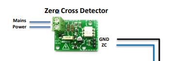
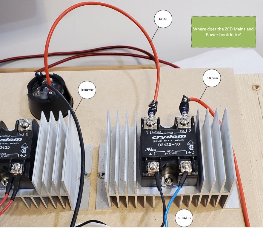
QUESTION: SSR & ZCD Wiring I currently have my blower wired like the attached example and I provided an actual pic as well. What I don't have yet wired for the blower is the ZCD portion. Here are my questions:
jbrux4 attached the following images:
R/
Jared |
|
|
|
| greencardigan |
Posted on 12/15/2019 7:02 PM
|
 1 1/2 Pounder  Posts: 1185 Joined: November 21, 2010 |
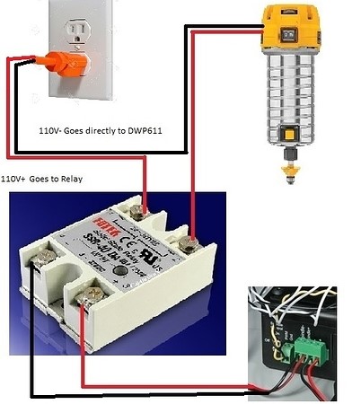
Glad you got the LCD sorted. Have you seen the wiring diagram attached? I don't really understand the difference between Q1 and Q2. You need power wires going from the main power input to the ZCD mains connector and also from the main power input to the blower via the SSR as per the attachment. I run ground from my outlet through to the metal parts on my roaster.
greencardigan attached the following image:

|
|
|
|
| jbrux4 |
Posted on 12/15/2019 8:30 PM
|
|
1/4 Pounder Posts: 139 Joined: October 26, 2019 |
Quote greencardigan wrote: Glad you got the LCD sorted. Have you seen the wiring diagram attached? I don't really understand the difference between Q1 and Q2. You need power wires going from the main power input to the ZCD mains connector and also from the main power input to the blower via the SSR as per the attachment. I run ground from my outlet through to the metal parts on my roaster. That wiring diagram only confuses me, and your explanation did not provide me clarity. I updated my picture to include line numbers if that would help in an "explain like i'm five" way. The blower is on its own 110v circuit as well. Thank you for your info. Sorry if my lack of electrical diagram to implementation is lacking. R/
Jared |
|
|
|
| jbrux4 |
Posted on 12/15/2019 9:19 PM
|
|
1/4 Pounder Posts: 139 Joined: October 26, 2019 |
Quote jbrux4 wrote: Quote greencardigan wrote: Glad you got the LCD sorted. Have you seen the wiring diagram attached? I don't really understand the difference between Q1 and Q2. You need power wires going from the main power input to the ZCD mains connector and also from the main power input to the blower via the SSR as per the attachment. I run ground from my outlet through to the metal parts on my roaster. That wiring diagram only confuses me, and your explanation did not provide me clarity. I updated my picture to include line numbers if that would help in an "explain like i'm five" way. The blower is on its own 110v circuit as well. Thank you for your info. Sorry if my lack of electrical diagram to implementation is lacking. I went and roasted some beans on my flour sifter set up, and came back up. Looking at CK's example, I've applied it to my wiring pic. I've added in where I think the wires should join in. Are there any issues with how I think it goes? 
jbrux4 attached the following image:

R/
Jared |
|
|
|
| greencardigan |
Posted on 12/15/2019 9:32 PM
|
|
1 1/2 Pounder Posts: 1185 Joined: November 21, 2010 |
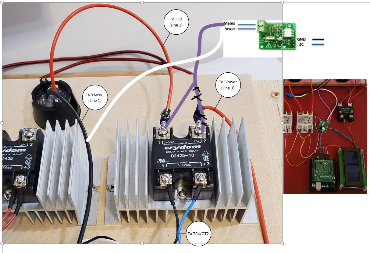
I think it need to be like the attached modified image with the purple wire connected to the other terminal on the SSR. I'm assuming the black circular thing is where the power enters your controls. The power going to the ZCD needs to be always on.
greencardigan attached the following image:
|
|
|
|
| jbrux4 |
Posted on 12/15/2019 9:54 PM
|
|
1/4 Pounder Posts: 139 Joined: October 26, 2019 |
Quote greencardigan wrote: I think it need to be like the attached modified image with the purple wire connected to the other terminal on the SSR. I'm assuming the black circular thing is where the power enters your controls. The power going to the ZCD needs to be always on. The black circular thing is the power inlet bringing in the 110v. OK, so it looks like I need to do an wire cap on Line 1 or do a bus terminal thing. I can just do a fork connector for the connection to the SSR. Thanks for your help. Hopefully someone else can verify the connections before I commit and do some wirescaping. R/
Jared |
|
|
|
| jbrux4 |
Posted on 12/23/2019 11:41 AM
|
|
1/4 Pounder Posts: 139 Joined: October 26, 2019 |
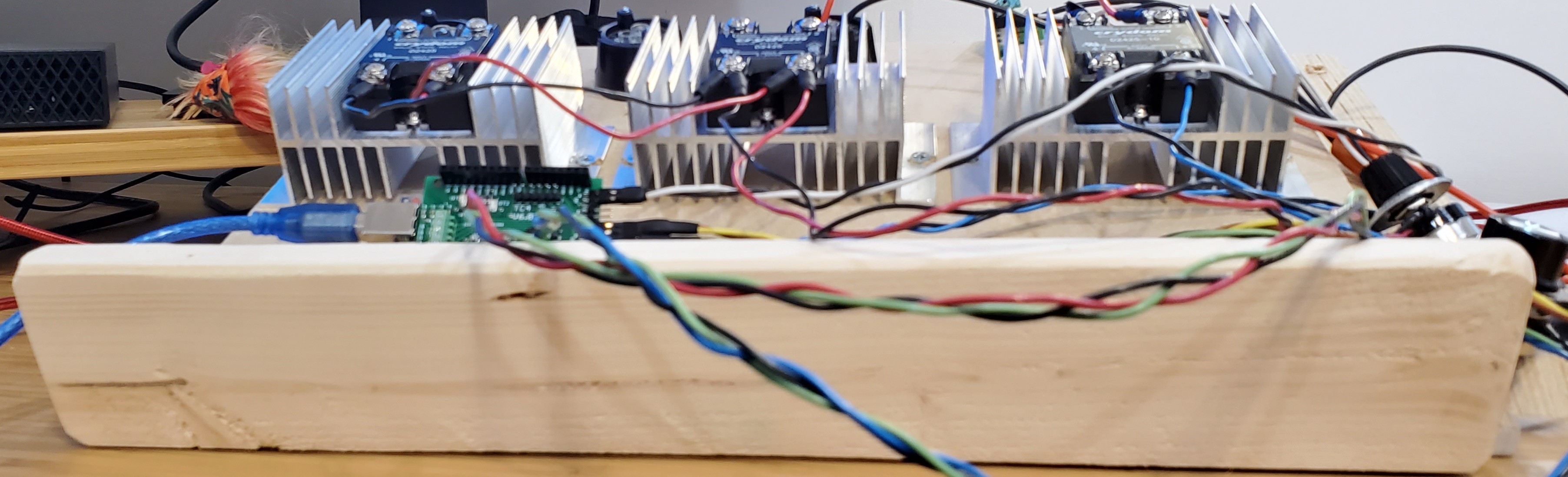
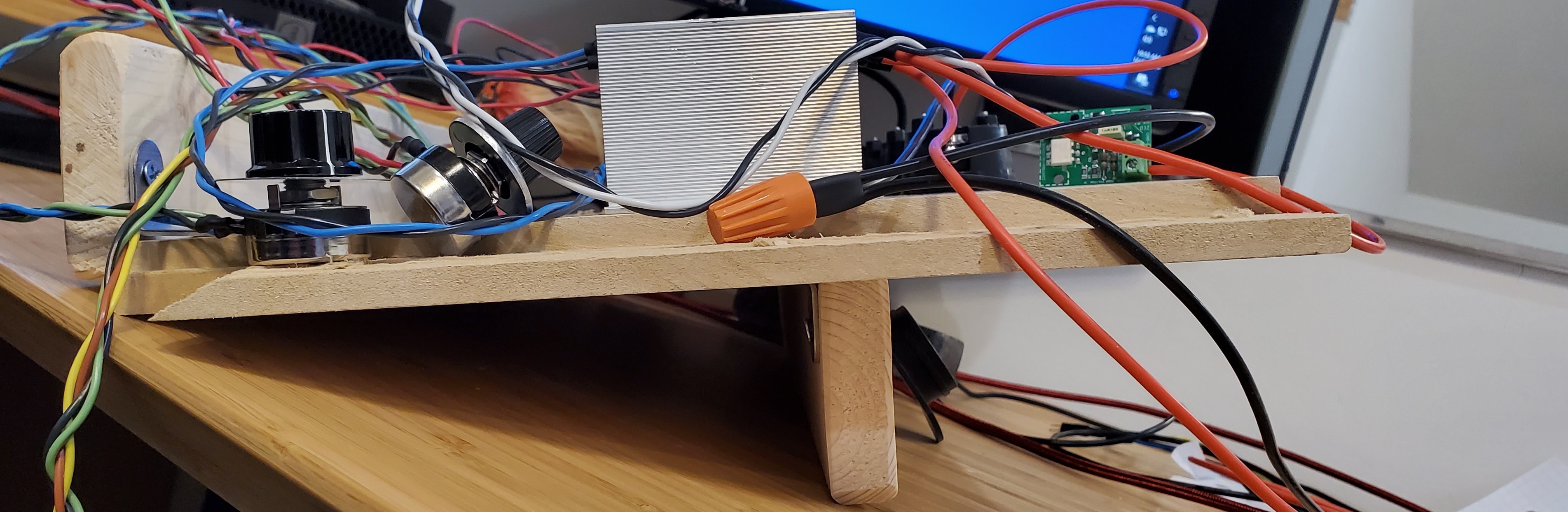
I have run a successful test of the blower and achieved variable control from Artisan and the Potentiometer in separate tests. For those who don't know, the user.h file is set up for Artisan by default and you have to uncomment the ANLG2 line to enable the potentiometer. Thank you for the assistance to correct the wiring. Here is how I have set-up the wiring. 
jbrux4 attached the following image:

Edited by jbrux4 on 12/24/2019 4:33 PM R/
Jared |
|
|
|
| jbrux4 |
Posted on 12/23/2019 2:50 PM
|
|
1/4 Pounder Posts: 139 Joined: October 26, 2019 |
One of the funniest but true statements I've read from this site with regards to getting into a build. Quote ShelfieSchtick wrote: Thanks! The rabbit hole gets deeper... I'm looking at doing a small-batch fluidbed build now. Lots of inspiration here! Quote btreichel wrote: Nah, yo got to drink the potion like Alice to really see the size of the rabbit hole you're in. https://forum.hom...post_69888 For me, with every step comes some new threshold breached and new knowledge necessary to move to the next. It takes some perseverance. But, I am glad I took this on. Still have a ways to go though. Yes, I drank the potion. R/
Jared |
|
|
|
| Husamka |
Posted on 12/24/2019 8:46 AM
|
|
1/4 Pounder Posts: 56 Joined: September 16, 2016 |
As SSR "NTD2425-10" is obsolete and not available. What's the alternative model ? |
|
|
|
| jbrux4 |
Posted on 12/24/2019 9:44 AM
|
|
1/4 Pounder Posts: 139 Joined: October 26, 2019 |
Quote If you go to https://www.mouse...3sCw%3D%3D then scroll down to the Similar Product section, it shows the D2425-10 as the product. Its link is https://www.mouse...K8TA%3D%3D. Here is the one I got: https://m.grainge...f0b983f3ac. Edited by jbrux4 on 12/24/2019 10:05 AM R/
Jared |
|
|
|
| Husamka |
Posted on 12/24/2019 10:47 AM
|
|
1/4 Pounder Posts: 56 Joined: September 16, 2016 |
Jared, Thank you. Just now I noticed its in your diagram. |
|
|
|
| jbrux4 |
Posted on 12/24/2019 4:31 PM
|
|
1/4 Pounder Posts: 139 Joined: October 26, 2019 |
Quote These are just logical diagrams to make sure I am hooking up things correctly. I will have build episodes where I list out the actual parts. But, I have changed the diagram in order to avoid confusion. Thanks for bringing that to my attention. R/
Jared |
|
|
|
| jbrux4 |
Posted on 12/24/2019 4:59 PM
|
|
1/4 Pounder Posts: 139 Joined: October 26, 2019 |
QUESTION: Where does neutral go? Please help me determine the wiring for the elements. I am running each element on its own 110V circuit and each having its own SSR. The method is "in parallel", which I think is indicated by the connections between SSR#1 and SSR#2 on terminals 3&4. I think I have the "hot" lines correct, but I am unsure about the neutral. I'll accept any pointers or definitive info. Thanks again. 
jbrux4 attached the following image:

R/
Jared |
|
|
|
| greencardigan |
Posted on 12/24/2019 5:44 PM
|
|
1 1/2 Pounder Posts: 1185 Joined: November 21, 2010 |
Neutrals go straight from the input plugs to the second terminal on the corresponding element. |
|
|
|
| jbrux4 |
Posted on 12/24/2019 6:26 PM
|
|
1/4 Pounder Posts: 139 Joined: October 26, 2019 |
Quote greencardigan wrote: Neutrals go straight from the input plugs to the second terminal on the corresponding element. I thought that, but it seemed too easy. Thanks for the help once again. R/
Jared |
|
|
|
| jbrux4 |
Posted on 12/25/2019 10:03 AM
|
|
1/4 Pounder Posts: 139 Joined: October 26, 2019 |
Depending on the order of operations for your build, a test bench may come in handy. Mine is really simple, and it enhanced the ease of wiring and placement of things. It allows various configurations and allows me to gauge the size of an enclosure for the final build. It required 3 pieces of wood and 4 brackets.
jbrux4 attached the following images:
R/
Jared |
|
|
|
| jbrux4 |
Posted on 01/04/2020 6:42 PM
|
|
1/4 Pounder Posts: 139 Joined: October 26, 2019 |
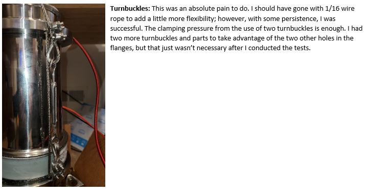
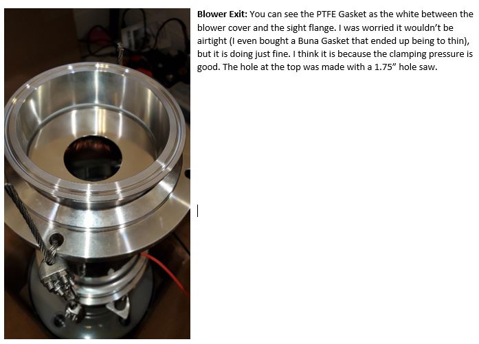
Build Episode 2: Blower Assembly Disclaimer: This is how I did it. You don?t have to do it this way. If I have done something detrimental to the safety of myself or others, please let me know. Discussion: Assemble all the parts and pieces for the thru-flow blower. This includes the intake/silencer, sanitary fittings, gaskets, blower, and clamping pressure via balustrade cable. Side Note: Nothing was easy. At every turn is a challenge to overcome. I would have liked for it all to have worked out according to what I thought it should have worked out to. This is why I can?t exactly go through each step with detail. I must only show a finished result and explain the pieces. How I got there, in some cases, is still a mystery to me  Goal(s): 1. Assemble from the intake to the blower exit. 2. Minimize air leakage if/when/where found. 3. Test using Artisan for variable control. 4. Test using Potentiometer for variable control.      
jbrux4 attached the following images:


Edited by jbrux4 on 01/04/2020 6:49 PM R/
Jared |
|
|
|
| shortyjacobs |
Posted on 01/04/2020 7:53 PM
|
|
Newbie  Posts: 44 Joined: September 24, 2014 |
That is one pretty looking roaster!
-Keith
|
|
|
|
| jbrux4 |
Posted on 01/07/2020 9:44 AM
|
|
1/4 Pounder Posts: 139 Joined: October 26, 2019 |
Quote Well, it is for my wife. The other goals are to make it functional and versatile. The design changes on the fly resulted in too many connections at the bottom, but I can reduce them later. I had to incorporate the sight flanges because they are quite impressive pieces, and that caused the additional pieces. But anyways, it is coming together. The heat pipe is next. R/
Jared |
|
|
|
| jbrux4 |
Posted on 01/14/2020 9:02 AM
|
|
1/4 Pounder Posts: 139 Joined: October 26, 2019 |
Success!! Well, success to a certain degree. I roasted 3 batches using full manual control. I did 2 100g batches and 1 150g batch. The blower ran at 12%-16% respectively. The heating elements ran at 40%-50%. The set-up was Frankenstein at best. Cords everywhere. 1 heating element was on a 14AWG 8 ft extension cord while the other element was on a 14 AWG 100ft extension cord ? both on 15A non-dedicated circuits. I think this means that the elements, when using 12AWG cords and each on a 20A dedicated circuit, they will run more efficiently and at higher capacity. I was able to clearly hear 1st, and, in the 3rd batch, 2nd crack. The roasts came out even ? no scorch marks whatsoever. Cool down phase was accomplished by turning off the heaters and turning up the blower to approximately 50%. Bean discharge was accomplished by undoing a tri-clamp and then dumping the beans. Problems? Of course. My heat pipe thermocouple, I think is about 40F to low. I have a calibrated external thermocouple that reads 40F higher when in higher temps into the 300?s and 400?s. This is really bothersome, and I ended up roasting the beans too fast ? achieving FC at like 6 minutes ? plus I am not used to the efficiency of getting the heat to the bean. I definitely have to learn the feel of the system. I didn?t even have the BT thermocouple plugged in. If you are asking why I roasted even though I clearly am not finished with the build: my wife wanted fresh roasted beans for her birthday on this roaster that is ?for her?. She was happy and impressed with its capabilities ? just two dials. Yes, there is much more to it when hooked into Artisan or Roastlogger, but that will come later. Anyways ? I am thrilled that this thing even works. I will post more on the heat pipe build soon. I also need to get the enclosure for all the electric components ? and I keep changing my mind on the enclosure. I will conduct better testing later. Like I said, this was a ?proof of concept? roast to appease the Mrs. R/
Jared |
|
|
|
| jbrux4 |
Posted on 01/14/2020 8:23 PM
|
|
1/4 Pounder Posts: 139 Joined: October 26, 2019 |
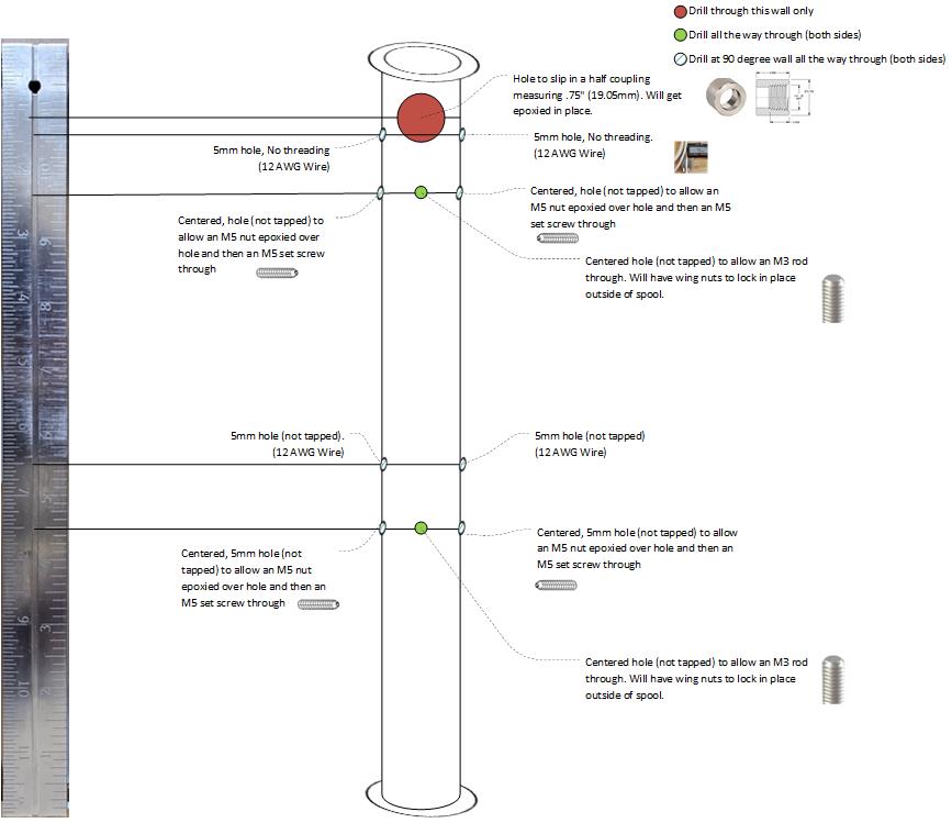
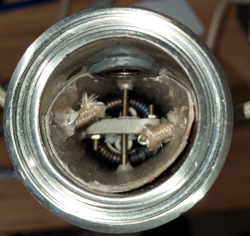
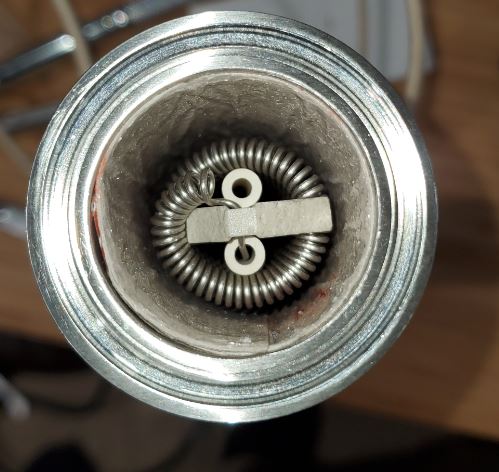
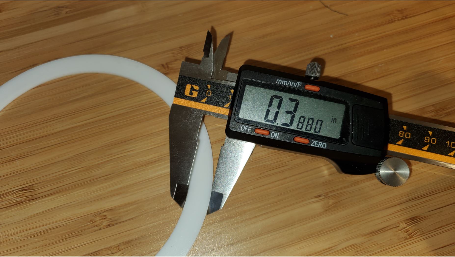
Build Episode 3: Heat Pipe and Reducer Assembly Disclaimer: This is how I did it. You don?t have to do it this way. If I have done something detrimental to the safety of myself or others, please let me know. Discussion: Fabricate and assemble the heat pipe with necessary pieces to center and suspend heating elements in pipe, accept heating element set screws, and thermocouple. Fabricate the funnel reducer (roast chamber) for the thermocouple. Goals and Procedures: 1. Fabricate the heat pipe and funnel reducer: This one was easy. Took it to a local machine shop, got the machinist interested in my project (it helped that he and his wife enjoy coffee), provided the drawings, and got the pieces drilled to specifications. It wasn?t free, but it was heavily discounted. Of course, I will bring him some roasted coffee. The pipe and reducer were drilled according to the diagrams below. What was unexpected and caused some extra milling were the half couplings not accepting the pipe plug k-type thermocouples fully. The machinist had to mill off a significant portion of the 1/8? half coupling and a little bit off the ?? coupling to get the thermocouple element to extend past the half coupling and into the insides of the pipe and reducer. He tried tapping, but the factory couplings only had their corresponding size NPT tap inserted just past the taper. So, the further into the half coupling the further reduced circumference of the thread ? the taper. My thermocouples would only go in partially. If I ever want to replace the half couplings with a known fully threaded, full circumference fitting, I can just heat the J-B weld that currently holds in the half couplings to above 650 and flake the stuff off.  2. Size and cut Mica sheet: Insert, mark, and cut/puncture holes to allow parts and pieces to enter heat pipe: I used scissors for a rough cut and then used a paper cutter to straighten the edges. I cut it the length of the entire heat pipe ~12?. I rolled the mica around the outside of the heat pipe to form it in order to prevent creases to develop (creases will develop if you don?t use a form). I then inserted the mica and made sure it was as tight to the inside pipe wall as possible. Using all of the existing holes in the heat pipe, I marked all of the holes using a pen. I removed the mica and then cut or punctured where I needed holes. Because the ?? NPT half coupling extends past the inner wall, I had to cut the mica from the bottom of the circumference of the half coupling to the top of the mica to allow it to slip all the way in. Otherwise, the lip of the mica would have gotten stuck on the bottom of the half coupling. 3. J-B Weld appropriate pieces to half couplings and to accept set screws: I used J-B Weld to attach the ?? half coupling to the heat pipe and a 1/8? coupling to the reducer. The half couplings were somewhat friction fit, but I roughed up all the mating areas, applied J-B Weld, mated, and let cure for 24 hours.  The x4 M5 set screws - to prevent lateral movement of the heating elements - required an M5 nut to allow proper threading of the set screw. I used flanged serrated M5 nuts, roughed the mating areas, and then applied J-B Weld, mated, and let cure for 24 hours. I had one that wasn?t lined up perfectly, so I pulled out my heat gun, heated the cured J-B weld above 650F and it came/flaked right off. I reapplied, let cure for 24 hours, and it was lined up perfectly.  4. Cut x2 M3 threaded rod to size and file to accept m3 nut: I used typical aviation snips to cut the M3 threaded rod to extend through the heat pipe on both sides. Because I have wing nuts on each end holding the rod in place and M3 nuts adhered to the heating element for suspension in the pipe, I had to make sure the threaded rod ends could accept a threaded nut. The ends, unless you get extremely lucky or have some other kind of tool or method, do not accept the nut. Through trial and error, I came upon the following method. Using a metal file with a rounded side, I moved the threaded rod back and forth while I constantly rocked the file. It took a few minutes per end to get the nut to accept flawlessly. File it, check, file it, check, file it, check. Eventually, I saw the nut getting closer and closer to perfect threading. I wasted a lot of time using the flat part of the file, trying to hacksaw a 90 degree and then chamfering the ends, etc. 5. Install the mica into the pipe: I already have the holes cut out or punctured, so I slipped in the mica being certain to line up the holes. 6. Wire heating elements: I started with the top element. I ran two lengths of cord through the holes and down through the pipe. I attached each of the ring terminals to the element and then pulled the element up into its general area inside the pipe by pulling on the two wires. I then put in the M3 threaded rod through the hole, threaded the element, then out the other hole making sure it was centered (not touching the mica). I then threaded the M5 set screws to the outside edges of the heating element?s ceramic. Heating element 1 in place. The bottom heating element is much closer to a pipe outlet, but I still had to use two lengths of cord as before - just shorter this time.     7. Install the thermocouples: Apply thread tape to threads and then threaded them into place. Materials: M5 Stainless Steel, Flanged, Serrated Nuts, QTY: 4 ?? Stainless Steel NPT Half Coupling ?? NPT K-Type Pipe Plug Thermocouple, Exposed Junction 1/8? Stainless Steel Half Coupling 1/8? K-Type Pipe Plug Thermocouple, Grounded Junction M3 316 Stainless Steel Threaded Rod, Qty 2 M3 304 Stainless Steel Lock Washer, Qty: 4 M3 304 Stainless Steel Wing Nut, Qty: 4 12 AWG High Heat Ring Connector, Qty: 4 High Heat Electrical Wire, Qty: 4 Heating Elements, Qty: 2 Tri-Clamp Spool (Heat Pipe), 304 Stainless Steel 4? to1.5" Funnel Reducer, 304 Stainless Steel J-B Weld Thread Tape Local Machine Shop
jbrux4 attached the following images:


Edited by jbrux4 on 01/16/2020 11:40 AM R/
Jared |
|
|
|
| jbrux4 |
Posted on 01/19/2020 8:16 PM
|
|
1/4 Pounder Posts: 139 Joined: October 26, 2019 |
Testing Results Parameters:
Results: Blower %; Element%; Temp Achieved; Sound dBA 20; 50; 305; 79.8 20; 60; 378; 79.8 30; 70; 396; 82.5 30; 80; 449; 82.5 30; 75; 436; 82.5 50; 85; 422; 84.2 50; 70; 372; 84.2 60; 70; 359; 85.5 60; 90; 423; 85.5 70; 90; 420; 86.7 100; 100; 442; 87.2 My take: The Perf Plate with the fine mesh produce a diminishing return rate/back pressure that I will be able to determine once I get enough beans to test. I am currently running really low. When I get my next 5lb bag, I will test. The air leaks where the high temp cables egress the heat pipe are of little concern. I had no reason to test the system with the intake/silencer removed because the equipment kept indicating "give me more power" while not being too loud. I am really happy with the results.
jbrux4 attached the following image:

Edited by jbrux4 on 01/19/2020 8:22 PM R/
Jared |
|
|
|
| cdrake39 |
Posted on 01/21/2020 10:04 AM
|
|
1/4 Pounder Posts: 83 Joined: August 08, 2019 |
Wow!! Very nice build - the attention to detail is great. Using the sight glass is such a great idea, makes for easy connections with those tri-clamp fittings. I may entertain the idea of using those on my build, right now I have to weld some connections that I'm not a huge fan of. May I ask where you sourced those parts? And how accurate are the dimensions listed in specs? I have a 4" x 8" (actual OD is 3.96") glass candle holder now that plan to use for the roast chamber - I wonder if I could just source the sight glass flanges... |
|
|
|
| jbrux4 |
Posted on 01/22/2020 12:31 AM
|
|
1/4 Pounder Posts: 139 Joined: October 26, 2019 |
Quote cdrake39 wrote: Wow!! Very nice build - the attention to detail is great. Using the sight glass is such a great idea, makes for easy connections with those tri-clamp fittings. I may entertain the idea of using those on my build, right now I have to weld some connections that I'm not a huge fan of. May I ask where you sourced those parts? And how accurate are the dimensions listed in specs? I have a 4" x 8" (actual OD is 3.96") glass candle holder now that plan to use for the roast chamber - I wonder if I could just source the sight glass flanges... I was unable to source just sight flanges when I tried. Because I was unsuccessful, I went ahead with the full sight glass. The pics have the measurement of the gasket that is just undersized of the flange ID where the sight glass sits. Attached also is the list of materials. If you need any more info, just ask. If you need an exact measurement of the flange ID, I need to add some gasket stuff to the inside of the blower housing. I can take one of the flanges off and take a measurement. Also, the sight glass is heavy. With it sitting on top of a 1.5" heat pipe there is always potential for something bad to happen when attaching it or removing it because of the tri-clamp being involved. I don't have a bean dumping mechanism, so I literally have to undo the tri-clamp while holding the sight glass, with a thermocouple in the chamber, then dump the beans - just gotta be careful and wear a glove for the because of the heat. What I need to do is to fabricate some type of handle attached to each of the flanges to aid in the handling of the sight glass when attaching or detaching. The handle is a necessity really. That will happen eventually.
jbrux4 attached the following file:
jbrux4 attached the following images:

Edited by jbrux4 on 01/22/2020 10:28 AM R/
Jared |
|
|
|

| Jump to Forum: |
Powered by PHP-Fusion Copyright © 2024 PHP-Fusion Inc
Released as free software without warranties under GNU Affero GPL v3
Designed with ♥ by NetriXHosted by skpacman