
Login

Shoutbox
You must login to post a message.
renatoa
07/26/2024 3:49 PM
Bill grubbe and Jk, 
allenb
07/26/2024 5:15 AM
Spiderkw Welcome to HRO!

renatoa
07/24/2024 8:31 AM
ramiroflores and John123,

 ?
?
?renatoa
07/21/2024 1:18 AM
 , Luislobo
renatoa
07/19/2024 11:28 AM
Koepea,
Forum Threads
Newest Threads
Skywalker roaster modsBackground Roast Iss...
Hello from Arkansas
TC4ESP
Green coffee reviews
Hottest Threads
| Skywalker roaster... | [375] |
| TC4ESP | [115] |
| War on Farmers by... | [47] |
| Adventures in flu... | [26] |
| Hello! (soon) Roa... | [17] |
In Memory Of Ginny

Donations
Latest Donations
dmccallum - 10.00
JackH - 25.00
snwcmpr - 10.00
Anonymous - 2.00
Anonymous - 5.00
dmccallum - 10.00
JackH - 25.00
snwcmpr - 10.00
Anonymous - 2.00
Anonymous - 5.00
Users Online
Guests Online: 6
Members Online: 0
Total Members: 8,393
Newest Member: Bill grubbe
Members Online: 0
Total Members: 8,393
Newest Member: Bill grubbe
View Thread
Who is here? 1 guest(s)
Page 1 of 2: 12
|
 Mean Time To Failure for FB Elements
|
|
| CK |
Posted on 02/15/2020 12:38 PM
|
|
1/2 Pounder  Posts: 252 Joined: December 07, 2018 |
R&D at its finest... sorry for your temporary set backs. Any idea of the amperage you're putting through that connection? I'm reading about dissimilar metal connections and negative effects of high current at the connection point. |
|
|
|
| jbrux4 |
Posted on 02/15/2020 6:25 PM
|
|
1/4 Pounder  Posts: 139 Joined: October 26, 2019 |
In trying to find a good solution, I am thinking that the male part of a spade connector could work. It has a tiny hole and a large surface area. I could make the hole bigger if needed to fit on the tiny screw. I would have to find a high temp non-insulated connector. Anybody see any issues with this potential solution? 
jbrux4 attached the following image:

R/
Jared |
|
|
|
| allenb |
Posted on 02/15/2020 7:11 PM
|
 Administrator Posts: 3869 Joined: February 23, 2010 |
Wow, you are very resourceful! That should work fine. I would cut the plastic insulator off before crimping and you should be good to go by drilling the proper hole diameter. Also, I would use a washer in between the machine screw head and spade terminal.
1/2 lb and 1 lb drum, Siemens Sirocco fluidbed, presspot, chemex, cajun biggin brewer from the backwoods of Louisiana
|
|
|
|
| jbrux4 |
Posted on 02/15/2020 8:56 PM
|
|
1/4 Pounder Posts: 139 Joined: October 26, 2019 |
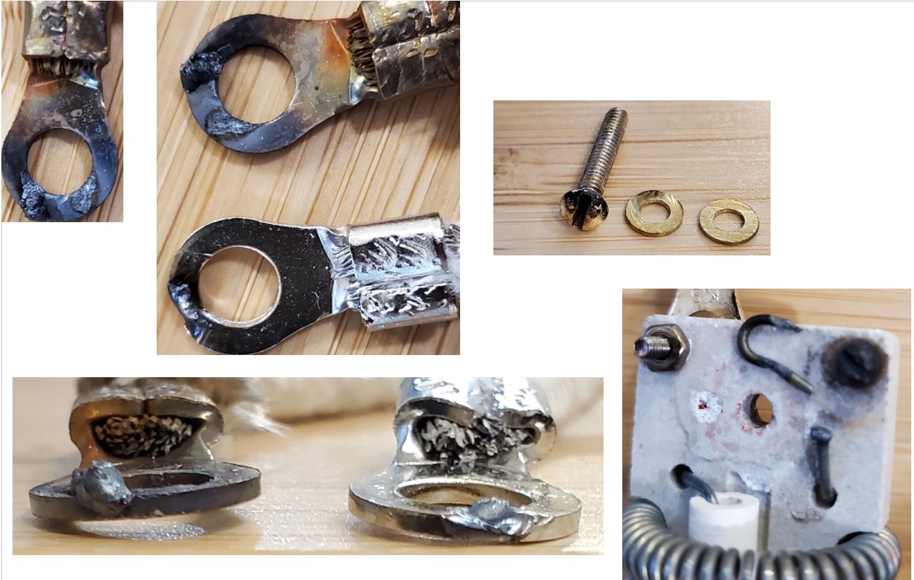
Quote CK wrote: R&D at its finest... sorry for your temporary set backs. Any idea of the amperage you're putting through that connection? I'm reading about dissimilar metal connections and negative effects of high current at the connection point. MFR documentation puts it at 120V, 60Hz, 14.5A, 1740W. I don't run at 100% ever. I get into the 80s and 90s towards last quarter of the roast. The wire is high temp nickel coated copper wire. The terminal is nickel coated high temp. I think the screws, washers, and nuts that come with the element are brass - just from the color of the material. The element is nichrome. Here are more images of the burnt connections.  Side Note: Also, I attached a file with my energy use estimate/calculation. I am using it for my break-even analysis workbook, and I want to know it produces the correct output. Does it seem correct?
jbrux4 attached the following file:
jbrux4 attached the following image:
R/
Jared |
|
|
|
| renatoa |
Posted on 02/16/2020 4:07 AM
|
|
Administrator Posts: 3104 Joined: September 30, 2016 |
Intrigued that the other terminal connection looks fine... I would investigate how/what are they different... I would try the following sandwich: - washer - element wire, cut to remove any rust and melted drops, then coiled around the screw in a single loop - washer - eyelet with AWG12 wire Edited by renatoa on 02/16/2020 4:13 AM |
|
|
|
| jbrux4 |
Posted on 02/21/2020 11:28 AM
|
|
1/4 Pounder Posts: 139 Joined: October 26, 2019 |
Quote renatoa wrote: Intrigued that the other terminal connection looks fine... I would investigate how/what are they different... I would try the following sandwich: - washer - element wire, cut to remove any rust and melted drops, then coiled around the screw in a single loop - washer - eyelet with AWG12 wire I've got my high temp male spade connectors and ceramic washers. My sandwich will be as follows: Ceramic element backer, element nichrome, male spade connector, ceramic washer, then screw head. I am thinking I need to get a new element that has a fully in tact nicrome hook. The way I see it, once I cut the degraded nichrome hook off, what's next? What materials and what method could I use to extend the nichrome wire back around the screw? R/
Jared |
|
|
|
| renatoa |
Posted on 02/21/2020 3:19 PM
|
|
Administrator Posts: 3104 Joined: September 30, 2016 |
Just pull some wire from the coil element itself, 2-3 cm shorter will not change dramatically the power. |
|
|
|
| jbrux4 |
Posted on 02/21/2020 3:35 PM
|
|
1/4 Pounder Posts: 139 Joined: October 26, 2019 |
Quote renatoa wrote: Just pull some wire from the coil element itself, 2-3 cm shorter will not change dramatically the power. Gotcha. Thanks!!! I will be putting it all back together again and testing. I think the new set-up removes most of the issues/risks. R/
Jared |
|
|
|
| jbrux4 |
Posted on 02/23/2020 3:38 PM
|
|
1/4 Pounder Posts: 139 Joined: October 26, 2019 |
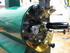
I redid the connections and the elements work. The problem now is that I have one runaway element meaning that once it gets plugged in it heats up. The TC4 or SSR stopped regulating the power?!? The other element gets regulated just fine. What would be a good approach to determining or finding the issue? I have switched the elements to a particular power source, and the element that is hooked up to a particular run becomes the runaway element. I am putting my money on the SSR, but would def want to hear from the masters. Thanks. Here is the wiring diagram.... 
jbrux4 attached the following image:

Edited by jbrux4 on 02/23/2020 3:58 PM R/
Jared |
|
|
|
| shortyjacobs |
Posted on 02/23/2020 3:49 PM
|
|
Newbie  Posts: 44 Joined: September 24, 2014 |
When SSRs fail, they typically fail closed ("ON"). Likely, when the element shorted out and melted, it did some damage. The SSR may be toast. Try switching SSRs with each other - does the other element now run unregulated? Check the SSRs with a multimeter. When off, or disconnected, there should be no continuity across the high voltage side. If there is, that SSR is dead dead dead.
-Keith
|
|
|
|
| jbrux4 |
Posted on 02/23/2020 4:00 PM
|
|
1/4 Pounder Posts: 139 Joined: October 26, 2019 |
Quote shortyjacobs wrote: When SSRs fail, they typically fail closed ("ON"). Likely, when the element shorted out and melted, it did some damage. The SSR may be toast. Try switching SSRs with each other - does the other element now run unregulated? Check the SSRs with a multimeter. When off, or disconnected, there should be no continuity across the high voltage side. If there is, that SSR is dead dead dead. I just updated my previous post with just that scenario. Looks like I will be replacing the SSR. I don't have a voltage tester, but I prob don't need one with the evidence thus far. Thanks for the input. R/
Jared |
|
|
|
| jbrux4 |
Posted on 02/23/2020 4:07 PM
|
|
1/4 Pounder Posts: 139 Joined: October 26, 2019 |
What I have solved is the electrical termination problem. No arcing or sparking this time. My sandwich is as follows: Element Ceramic Backer, Nichrome Wire, High Temp Male Spade Connector (I had to enlarge the hole diameter jusrt barely using a small drill bit and some pliers to hold the termination to keep it from spinning), mfr supplied washer (the ceramic ones are too brittle and crack under the slightest pressure), and the screw head. Here is a pic:  Male Spade Connectors: https://www.amazo...&psc=1
jbrux4 attached the following image:

R/
Jared |
|
|
|
| jbrux4 |
Posted on 02/27/2020 9:17 PM
|
|
1/4 Pounder Posts: 139 Joined: October 26, 2019 |
The runaway element was fixed by replacing the SSR. Easy fix, but money I didn't want to have to spend. And, actually, with an element always at 100%, roasting was actually easier to maintain a good RoR. There were less "slight" adjustments needed and it was predictable. I did 4 roasts like that. Oh well, back to the norm. Besides, who wants to have to unplug an element at cool down? Perhaps a toggle switch...hmmmmm, maybe. Couple things I learned from the SSR issue: * Never leave it plugged in when not in use * Always run the blower when plugging in the elements just in case an SSR is stuck in the "always on" position Anyways - case closed. Thanks to the forum for helping again!! R/
Jared |
|
|
|
| shortyjacobs |
Posted on 02/28/2020 1:30 PM
|
|
Newbie Posts: 44 Joined: September 24, 2014 |
Yep. I use a contactor relay upstream of my SSRs for a "positive shutoff". Mains power to the SSRs is only enabled once the fans are running and a roast has begun, and I cut power to the SSRs at the end of the roast with the contactor to start the cooldown phase. I don't trust SSRs as a positive "off", since they are just semiconductor chips that can fail...I like air separating my contacts when it really matters.
-Keith
|
|
|
|

Page 1 of 2: 12
| Jump to Forum: |
Powered by PHP-Fusion Copyright © 2024 PHP-Fusion Inc
Released as free software without warranties under GNU Affero GPL v3
Designed with ♥ by NetriXHosted by skpacman