
Login

Shoutbox
You must login to post a message.
renatoa
07/26/2024 3:49 PM
Bill grubbe and Jk, 
allenb
07/26/2024 5:15 AM
Spiderkw Welcome to HRO!

renatoa
07/24/2024 8:31 AM
ramiroflores and John123,

 ?
?
?renatoa
07/21/2024 1:18 AM
 , Luislobo
renatoa
07/19/2024 11:28 AM
Koepea,
Forum Threads
Newest Threads
Skywalker roaster modsBackground Roast Iss...
Hello from Arkansas
TC4ESP
Green coffee reviews
Hottest Threads
| Skywalker roaster... | [375] |
| TC4ESP | [115] |
| War on Farmers by... | [47] |
| Adventures in flu... | [26] |
| Hello! (soon) Roa... | [17] |
In Memory Of Ginny

Donations
Latest Donations
dmccallum - 10.00
JackH - 25.00
snwcmpr - 10.00
Anonymous - 2.00
Anonymous - 5.00
dmccallum - 10.00
JackH - 25.00
snwcmpr - 10.00
Anonymous - 2.00
Anonymous - 5.00
Users Online
Guests Online: 4
Members Online: 0
Total Members: 8,393
Newest Member: Bill grubbe
Members Online: 0
Total Members: 8,393
Newest Member: Bill grubbe
View Thread
Who is here? 1 guest(s)
 RobotDyn AC Light Dimmer Module
|
|
| jake415 |
Posted on 03/07/2022 3:06 AM
|
|
Newbie  Posts: 26 Joined: January 18, 2022 |
Right now I'm just testing the heater side since it seems simpler (no ZC). The PWM signal is connected and should work. When I use CONFIG_PAC3 for phase angle control on heater, and test the robotdyn (Vcc to OT1, PSM to GPIO PIN 9), there are no flashing lights and the robotdyn seems completely inactive. When I use CONFIG_PWM for PWM on heater, same connections, there are flashing lights and the robotdyn works. I'd like to use phase angel control but so far no luck. |
|
|
|
| renatoa |
Posted on 03/07/2022 6:44 AM
|
|
Administrator Posts: 3104 Joined: September 30, 2016 |
PAC requires ZCD, that's why is not working Without ZCD only PWM is available. |
|
|
|
| jake415 |
Posted on 03/07/2022 2:25 PM
|
|
Newbie Posts: 26 Joined: January 18, 2022 |
I didn't know that, problem solved  thanks thanks |
|
|
|
| dpecsok |
Posted on 03/14/2022 12:42 AM
|
|
Newbie Posts: 9 Joined: February 03, 2022 |
hello! im using the RobotDyn module to control an 1200w AC vac motor using PAC2 mode. ive been testing with both the motor and a lamp as well. problem is that the motor or light is either OFF or at 50% and higher. below 50% it seems motor and light are bit jittery like its being pulsed on and off. any suggestions is very much appreciated!
dpecsok attached the following image:

|
|
|
|
| dpecsok |
Posted on 03/14/2022 2:29 AM
|
|
Newbie Posts: 9 Joined: February 03, 2022 |
i read in a few other posts that this is common using PAC. i there a way to control the RobotDyn using PWM mode? if so what is the proper way to wire it? sorry im a noob ha! |
|
|
|
| renatoa |
Posted on 03/14/2022 3:26 AM
|
|
Administrator Posts: 3104 Joined: September 30, 2016 |
If motor is induction type, i.e. no brushes/sparks, then you need a special driver, called VFD, quite expensive. PAC works for the so called "universal" motors, those that are noisy even without load, to distinguish them from induction motors, which are quiet. Vac motors are universal type though, sounds strange what you report... connections from the diagram above are ok. The bulb also should work ok, though... you should experience no flickering with PAC control. Please, can you post a short video clip to see the bulb behavior ? PWM can be slow type, used to control heaters, in CONFIG_PWM mode, or fast type, output on IO3, to control DC fans or heaters using external drivers, choice depending on task. |
|
|
|
| dpecsok |
Posted on 03/14/2022 7:38 AM
|
|
Newbie Posts: 9 Joined: February 03, 2022 |
thanks for your feedback, i will try to make a video soon.. Quote renatoa wrote: PWM can be slow type, used to control heaters, in CONFIG_PWM mode, or fast type, output on IO3, to control DC fans or heaters using external drivers, choice depending on task. So in PWM mode its not possible to control an AC motor? |
|
|
|
| renatoa |
Posted on 03/14/2022 7:59 AM
|
|
Administrator Posts: 3104 Joined: September 30, 2016 |
The answer is no, for a mains powered AC motor. As we can read the descriptions in the user.h section listing the various configs: Code Download source //#define CONFIG_PWM // slow PWM on OT1 (heater); fast PWM output (3.922kHz) on IO3 (DC fan); ZCD not required ... PWM on IO3 means using a MOSFET driver, for a DC motor. For your task people usually use CONFIG_PAC2: Code Download source #define CONFIG_PAC2 // phase angle control using ICC on OT1 (heater) and OT2 (fan); IO2 used to read the ZCD Note of the above: even if not specified, ICC is used on OT1, for heater only, not on OT2, where phase angle control is used for fan. Even the other config modes listed after PAC2 can be used, depending on motor type and available electronics to drive it. Code Download source //#define CONFIG_PAC2_IO3HTR // phase angle control on OT1 (heater) and OT2 (fan); IO2 reads the req'd ZCD; IO3 reserved for fast PWM output for heater |
|
|
|
| renatoa |
Posted on 03/14/2022 8:14 AM
|
|
Administrator Posts: 3104 Joined: September 30, 2016 |
There is a possible reason that comes later in my mind... A motor is an inductive load, compared to a heater, which is mainly resistive load, even if it looks as a coil  A control element of an inductive load should be fitted with a RC circuit on the exit, called snubber. The first version of this dimmer, from the very first post of this thread, lacks this circuit, being appropriate for resistive loads, or very low power motors. There is a second version of this dimmer, signaled here first time in post #29 above, which is fitted with this snubber circuit, the components enclosed in ellipse in attached picture. If you have the first version dimmer you have to attach these two components externally, on same output terminals as the motor, as you can see here: https://en.wikipe...C_snubbers The values of components, how well I am able to read on the image, seems to be 10nF/400V for capacitor, and 1kO for the resistor. ~~~
renatoa attached the following image:

Edited by renatoa on 03/14/2022 8:22 AM |
|
|
|
| dpecsok |
Posted on 03/16/2022 5:15 AM
|
|
Newbie Posts: 9 Joined: February 03, 2022 |
renatoa thanks for your replies and input. heres a video, and you can see that there is a lot of flickering with the light and not so much dimming. im thinking maybe the dimmer module is not working properly or im doing something wrong ha! im looking into getting the updated version with the snubber circuits but im thinking that even without it shouldnt the light be dimming properly? link to video: Edited by renatoa on 03/16/2022 5:28 AM |
|
|
|
| renatoa |
Posted on 03/16/2022 5:35 AM
|
|
Administrator Posts: 3104 Joined: September 30, 2016 |
The only thing that comes in my mind at first look is that the zero cross pulses aren't triggered at the right moments. It can be diagnosed, but requires some code changes. How is the led on the board activity ? Follows the bulb ? |
|
|
|
| dpecsok |
Posted on 03/20/2022 12:09 AM
|
|
Newbie Posts: 9 Joined: February 03, 2022 |
Quote renatoa wrote: The only thing that comes in my mind at first look is that the zero cross pulses aren't triggered at the right moments. It can be diagnosed, but requires some code changes. How is the led on the board activity ? Follows the bulb ? So at 0% fan, no LED on. from 1-100% the OT2 LED on the TC4 & a LED on the Robotdyn turn on and stay on. from 1-50%ish , the light im dimming just flickers a lot like the video i posted earlier. 50% and above its seems like the light gets a little brighter but not gradually, more like it steps up every 20% or so. what code changes do you suggest to diagnose? thanks! |
|
|
|
| renatoa |
Posted on 03/20/2022 3:19 AM
|
|
Administrator Posts: 3104 Joined: September 30, 2016 |
In my fork copy, in the interrupt routine serving ZC detection, added here: https://github.co...l.cpp#L115 ...some code that check if there isn't a parasite triggering of a false zero cross, after the very first, assumed the legit. byte pinVal = digitalRead(INT_PIN); Code Download source if (pinVal == HIGH) { The falseCross variable, can be checked in the main application if you want more detailed diagnose. It is forbidden to send some output on serial line inside a interrupt routine, that's why any relevant info you want to know have to be stored in variables and checked outside. |
|
|
|
| dpecsok |
Posted on 03/20/2022 11:59 AM
|
|
Newbie Posts: 9 Joined: February 03, 2022 |
insert in between line 113 and 114? ... void ISR_ZCD() { TCNT1 = 0; // reset timer1 counter byte pinVal = digitalRead(INT_PIN); if (pinVal == HIGH) { // false triggering filter if ((millis() - lastCross) < 4 ) { falseCross = millis() - lastCross; return; } // perform AC monitoring lastCross = millis(); // timer0 ... is this a fix or a way to check the timing? how do i see the results of the diagnosis? |
|
|
|
| renatoa |
Posted on 03/20/2022 1:43 PM
|
|
Administrator Posts: 3104 Joined: September 30, 2016 |
Stooop, please ! This code is for a different version of TC4, adapted for ESP family of processors, and posted only as a proof of concept. Will not work by simply copy-pasted on original Arduino TC4, without a deeper understanding of programming. For example, surely that first line time reset shouldn't be there... and also there should be a closing } bracket somewhere further in the code, else would not compile, etc... Is better to wait for the current master of TC4 to add something equivalent for Arduino Uno, thoroughly checked, and committed in the official repository. This code is both a fix for multiple parasite zero crossings, and also a diagnose method, by checking the falseCross variable. Attached an image for a better understanding of the issue, which is VERY present in industrial environments, where a lot of heavy loads are started/stopped permanently. But also in household scenarios, in my home the record was eight such parasite triggering, that forced me to fix them in code. ~~~
renatoa attached the following image:

|
|
|
|
| renatoa |
Posted on 03/20/2022 2:01 PM
|
|
Administrator Posts: 3104 Joined: September 30, 2016 |
Before venturing too deep in these assumptions, a simple question: are you using OT2 for the fan control ? I.e. output pin D10? Because, if reversed, in PAC2 mode the OT1 control is different than OT2 ! |
|
|
|
| dpecsok |
Posted on 03/20/2022 11:06 PM
|
|
Newbie Posts: 9 Joined: February 03, 2022 |
coding is not my specialty so im waiting till i know for sure from someone who knows better! yes using PAC2 , OT2 for fan control robotdyn VVC to OT2 GRD to IO2 GRD ZC to IO2 PSM to D10 hopefully i have that correct |
|
|
|
| renatoa |
Posted on 03/21/2022 3:22 AM
|
|
Administrator Posts: 3104 Joined: September 30, 2016 |
Quote robotdyn VVC to OT2 Vcc connection to OT2 is questionable, because you have no guarantee there is a firm voltage on that pin. Also, there is no need for this connection, the RobotDyn board designer provided it for other custom applications. Not needed for TC4. In all my usages of various board models of this design, at least four units that I remember atm, I don't connect the Vcc pin. Edited by renatoa on 03/21/2022 8:05 AM |
|
|
|
| dpecsok |
Posted on 03/21/2022 3:47 AM
|
|
Newbie Posts: 9 Joined: February 03, 2022 |
wow! i think you just solved my issues pulled the VCC to OT2 and its working now with a light. now to try with a motor |
|
|
|
| renatoa |
Posted on 03/21/2022 3:07 PM
|
|
Administrator Posts: 3104 Joined: September 30, 2016 |
Credits goes to your Vcc <> VVC typo, that catch my attention |
|
|
|
| dpecsok |
Posted on 03/25/2022 12:39 AM
|
|
Newbie Posts: 9 Joined: February 03, 2022 |
fyi, i ordered the updated version with the snubber capacitors on the board but instead received an update to the updated version ha! looks like they removed the capacitors again .... size, heatsink, and AC connections are larger; about the size of an SSR now. trying to add a picture as an attachment but its not working... |
|
|
|
| iPa |
Posted on 03/27/2022 2:58 AM
|
|
Newbie Posts: 44 Joined: December 22, 2021 |
As soon I switched from ZCD module bought with the TC4 shield ("ZCDboard") to the ZCD from the Robodyn module ("ZCDrobodyn") I noticed a weird behavior change with the PID control. I made many tests to confirm this difference. For now I don't have any explanation, yes I should get out the oscilloscope... Any ideas of explanation about this difference, welcome ZCDboard result: A bit below the curve at the beginning but reached it soon, maybe need to increase ki 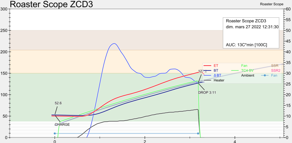 ZCDrobodyn result: A lot more oscillations in this case 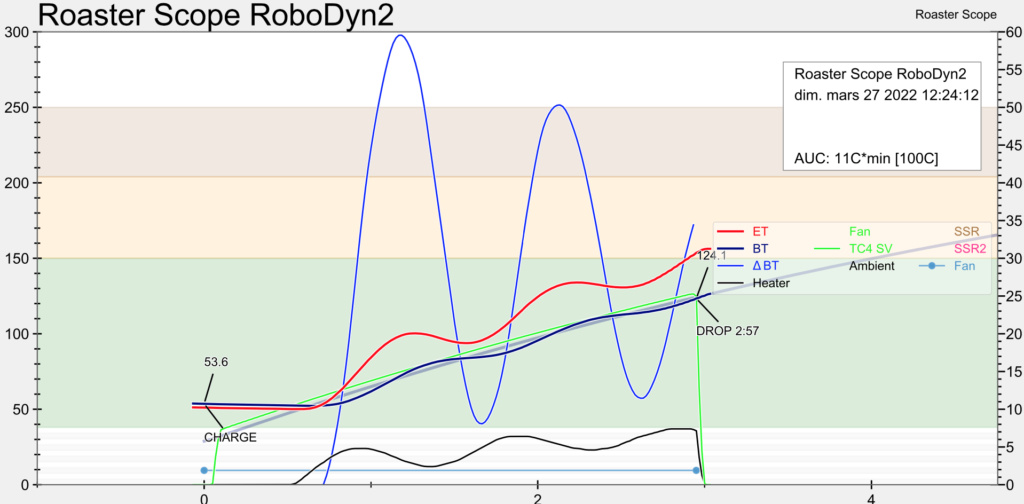 |
|
|
|
| renatoa |
Posted on 03/27/2022 3:40 AM
|
|
Administrator Posts: 3104 Joined: September 30, 2016 |
Is the LED on Arduino board lit both cases ? i.e. zcd working, a/c detected. Looks like you have on-off switching in the second scenario... |
|
|
|
| iPa |
Posted on 03/27/2022 9:49 AM
|
|
Newbie Posts: 44 Joined: December 22, 2021 |
The oscilloscope revealed some interesting things: - The signal polarity is not the same between this 2 boards !! - If the board is to not connected to VCC the signal is less good drived (so better to connect vcc). Need to have a look in the code to understand the impact of this reversed polarity, and what is expected. Maybe @renatoa have you some information about that ? ZCDboard with vcc 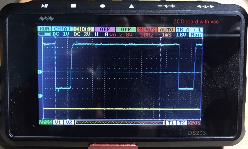 ZCDboard without vcc 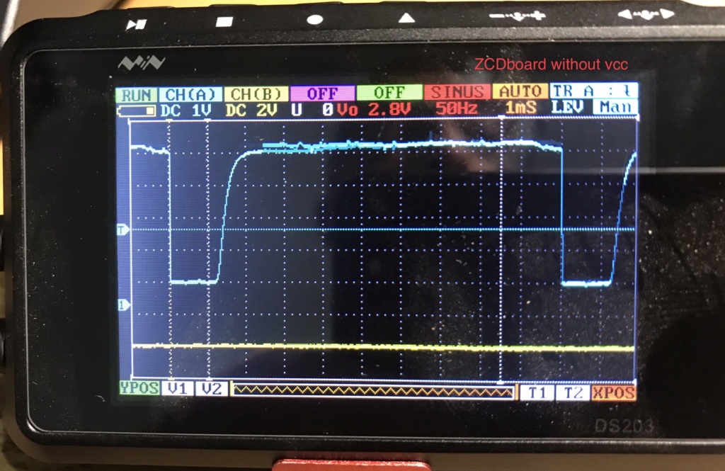 ZCDrobodyn note the inverted polarity compared to the ZCDboard (with vcc)  ZCDrobodyn without vcc 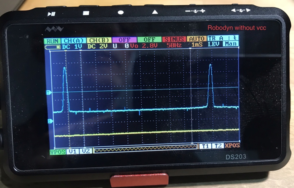 if someone has schematics about this 2 boards I am interested edit1: I found schematic for the Robotdyn but not for the NZDboard (mine is a verson 6.2) edit2: Found in the code: Expected> logic low indicates zero cross Interrup on falling edge> attachInterrupt( EXT_INT, ISR_ZCD, FALLING ); That means, ZCD interrupt will occurs about 1mS later with ZCDRobotdyn (1/2 period = 10mS = 10%), is that enough to explain the difference behavior, probably. Asap I will test with interrupt on the rising edge with the ZCDRobotdyn. Edited by iPa on 03/27/2022 10:44 PM |
|
|
|
| renatoa |
Posted on 03/28/2022 1:25 AM
|
|
Administrator Posts: 3104 Joined: September 30, 2016 |
Could be related to similar processes, as investigated some posts above, starting with #51. If not intriguing enough, in my TC4ESP fork I changed also the polarity, but for other reasons, without scoping the ZCD signal... My posts about with/without Vcc pin connected are related to robotdyn board only, never used another make, so can't comment about their behavior, without schematic. Edited by renatoa on 03/28/2022 1:38 AM |
|
|
|

| Jump to Forum: |
Powered by PHP-Fusion Copyright © 2024 PHP-Fusion Inc
Released as free software without warranties under GNU Affero GPL v3
Designed with ♥ by NetriXHosted by skpacman