
Login

Shoutbox
You must login to post a message.
renatoa
04/25/2024 2:03 AM
AGZ and Intercolcoffee

allenb
04/23/2024 7:01 PM
Paul Kalb

renatoa
04/23/2024 4:34 AM
Coffee_Rabbit_Hole
and Michaelion,
and Michaelion,
renatoa
04/21/2024 2:35 AM
compactjack and GreenGenie
 ?
?
?allenb
04/19/2024 8:27 AM
eximwind
Forum Threads
Newest Threads
Skywalker roaster modsHello from Montreal ...
War on Farmers by Su...
Kaleido Roaster PID ...
Rainfrog's Roastmast...
Hottest Threads
| Skywalker roaster... | [302] |
| Skywalker, the AL... | [214] |
| Skywalker Roasts | [94] |
| Rainfrog's Roastm... | [54] |
| War on Farmers by... | [40] |
In Memory Of Ginny

Donations
Latest Donations
dmccallum - 10.00
JackH - 25.00
snwcmpr - 10.00
Anonymous - 2.00
Anonymous - 5.00
dmccallum - 10.00
JackH - 25.00
snwcmpr - 10.00
Anonymous - 2.00
Anonymous - 5.00
Users Online
Guests Online: 4
Members Online: 0
Total Members: 8,227
Newest Member: AGZ
Members Online: 0
Total Members: 8,227
Newest Member: AGZ
View Thread
Who is here? 1 guest(s)
Page 2 of 2: 12
|
 Connecting a raspberry pi to artists scope: no readings...
|
|
| zamunda |
Posted on 06/29/2021 5:28 AM
|
 1/4 Pounder  Posts: 173 Joined: November 17, 2020 |
Hello, I would like to replace me dedicated device for temp-reading (Voltcraft 125-4) by these sensors (https://www.bitsandparts.nl/Thermocouple-Thermokoppel-versterker-MAX6675-breakout-board-SPI-p115827). I connected the 2 MAX6675 to my Raspberry Py and I am able to read the temps within a Python proram. Now I want to display these temps within Artisan so I changed under Config->Device->Meter to Config->Device->Prog and then pointed there to the Python script: #!/usr/bin/python2.7 # before import the max6675, you must save the max6675.py file at "/usr/lib/python2.7/dist-packages" # wiring # Raspberry MAX6675 # GND ------ GND # 5V ------ VCC # pin 18 ------ SCK # pin 22 ------ CS # pin 16 ------ SO # import max6675 module. import max6675 # set the pin for communicate with MAX6675 cs = 22 sck = 18 so = 16 # max6675.set_pin(CS, SCK, SO, unit) [unit : 0 - raw, 1 - Celsius, 2 - Fahrenheit] max6675.set_pin(cs, sck, so, 1) try: while 1: # read temperature connected at CS 22 a = max6675.read_temp(cs) # print temperature print a # when there are some errors with sensor, it return "-" sign and CS pin number # in this case it returns "-22" max6675.time.sleep(3) except KeyboardInterrupt: pass However, how do I hand this temp over to Artisan? Pointing to the script is not enough I guess since the script should at least run in the background while running Artisan as well but I did not get any further... Any suggestions/pointers? Thanks in advance!
zamunda attached the following image:

|
|
|
|
| renatoa |
Posted on 06/29/2021 7:06 AM
|
|
Administrator Posts: 3010 Joined: September 30, 2016 |
Please, check others similar experiences here: www.home-barista....58234.html |
|
|
|
| zamunda |
Posted on 06/29/2021 9:35 AM
|
|
1/4 Pounder Posts: 173 Joined: November 17, 2020 |
Hallo renatoa, SUCCES!!! Thanks for this link, I looked at it and saw that most of them are using it with Arduino but I would was looking for a Raspberry Pi-only solution. However, I noticed there that combining the program with MODBUS config might work. So I figured out how to write the temp from the program to the serial port and read it within Artisan by configuring the port under the MODBUS-tab... The working program looks now as follows: #!/usr/bin/python2.7 # before import the max6675, you must save the max6675.py file at "/usr/lib/python2.7/dist-packages" # wiring # Raspberry MAX6675 # GND ------ GND # 5V ------ VCC # pin 18 ------ SCK # pin 22 ------ CS # pin 16 ------ SO # import max6675 module. import max6675 #import serial module import serial # set the pin for communicate with MAX6675 cs = 22 sck = 18 so = 16 # max6675.set_pin(CS, SCK, SO, unit) [unit : 0 - raw, 1 - Celsius, 2 - Fahrenheit] max6675.set_pin(cs, sck, so, 1) try: while 1: # read temperature connected at CS 22 a = max6675.read_temp(cs) # print temperature print a ser = serial.Serial('/dev/ttyAMA0') # open serial port #print(ser.name) # check which port was really used ser.write(a) # write a string ser.close() # close port # when there are some errors with sensor, it return "-" sign and CS pin number # in this case it returns "-22" max6675.time.sleep(3) except KeyboardInterrupt: pass Thanks again!
zamunda attached the following images:


Edited by zamunda on 06/29/2021 9:41 AM |
|
|
|
| zamunda |
Posted on 06/29/2021 11:09 AM
|
|
1/4 Pounder Posts: 173 Joined: November 17, 2020 |
Hello Taking it a step further, how does Artisan expect to receive the data for 2 probes from the serial port, comma-separated like this: 23,28 ??? Tried this but did not work, any hints? Thanks |
|
|
|
| renatoa |
Posted on 06/29/2021 12:06 PM
|
|
Administrator Posts: 3010 Joined: September 30, 2016 |
From the serial port Artisan expects to receive them packed in various ways, depending on the device protocol. The most popular is TC4 I guess... so you should try to emulate a TC4 board, in order to be able to send something to Artisan. Artisan send a READ command, and the device should reply instantly, so you should have the values already acquired and processed, ready to build the packet. The TC4 packet reads as below: AT,ET,BT,3rdTC,4thTC,HTR,FAN,SP where: AT = ambient HTR,FAN = actual values, could be different than Artisan thinks they are, the hardware could have it's own reasoning... for example a heater cutoff when fan is under a given value. SP = PID setpoint, if PID active Temperature values should be scaled in the hardware to the units used by Artisan. Or viceversa, Artisan units set to match the hardware. One more (mandatory) thing, is a small handshake at the beginning of every roast... it consist of three commands, sent by Artisan, that the board should execute (or try to mimic this), and reply with a # sign, else Artisan will abandon and never sends READ commands. The three commands are: FILT, CHAN and UNITS. For a complete syntax, you can find the whole commands list here: https://github.co...mmands.txt Possible to be devices with simpler protocol, but not investigated. Edited by renatoa on 06/29/2021 12:12 PM |
|
|
|
| renatoa |
Posted on 06/29/2021 12:17 PM
|
|
Administrator Posts: 3010 Joined: September 30, 2016 |
One more notice... sincerely I am seriously puzzled why the RasPI version on Artisan see the serial devices as ModBUS things, because ModBUS protocol is one of the many ways a serial device can communicate, and is not simple at all... actually is the most complicate I know in this world of instrumentation communication. TC4 protocol is far more simpler, and also the various digital usb meters, as is Mastech MS6514, aren't related to ModBus way at all... |
|
|
|
| zamunda |
Posted on 06/29/2021 2:37 PM
|
|
1/4 Pounder Posts: 173 Joined: November 17, 2020 |
Quote renatoa wrote: From the serial port Artisan expects to receive them packed in various ways, depending on the device protocol. The most popular is TC4 I guess... so you should try to emulate a TC4 board, in order to be able to send something to Artisan. Artisan send a READ command, and the device should reply instantly, so you should have the values already acquired and processed, ready to build the packet. The TC4 packet reads as below: AT,ET,BT,3rdTC,4thTC,HTR,FAN,SP where: AT = ambient HTR,FAN = actual values, could be different than Artisan thinks they are, the hardware could have it's own reasoning... for example a heater cutoff when fan is under a given value. SP = PID setpoint, if PID active Temperature values should be scaled in the hardware to the units used by Artisan. Or viceversa, Artisan units set to match the hardware. One more (mandatory) thing, is a small handshake at the beginning of every roast... it consist of three commands, sent by Artisan, that the board should execute (or try to mimic this), and reply with a # sign, else Artisan will abandon and never sends READ commands. The three commands are: FILT, CHAN and UNITS. For a complete syntax, you can find the whole commands list here: https://github.co...mmands.txt Possible to be devices with simpler protocol, but not investigated. Hello renatoa, Thank you for your elaborated answer...to be honest, I was not aware that it is that complicated what I am trying to achieve: since connecting one sensor from the RP to Artisan was quite straightforward, I hoped to be able to connect one for ET as well. In fact, what I am trying to do is this: https://www.youtube.com/watch?v=M-j_JZCX-OI but then with the MAX6657 Do you see this still as feasible? |
|
|
|
| renatoa |
Posted on 06/29/2021 3:55 PM
|
|
Administrator Posts: 3010 Joined: September 30, 2016 |
Yes, should work, these chips are compatible and very close as code base. grencardigan is user here, he knows better this stuff. But one of his youtube comments reveal another thing you should be aware, this approach is somewhat a dead end: Quote I had issues getting phase angle control of an AC fan so gave up. In a different way, I found the same thing long time ago... tethered roasting could be more annoying than should be... so I found my way to have successful roasts without Artisan around. |
|
|
|
| greencardigan |
Posted on 06/29/2021 8:29 PM
|
 1 1/2 Pounder  Posts: 1185 Joined: November 21, 2010 |
Hi, yes that's my video. I was trying to eliminate the TC4 and Arduino from my Rpi <-> Arduino <-> TC4 setup. It was a while ago now so I don't recall all the details required to get it working. But a few vague memories are below. - The script might need to be made executable so it can be called from Artisan. - The script just needs to output the two temp values comma separated using a print statement. - The temps are the only thing that should be output from the script. - It shouldn't require serial or modbus. |
|
|
|
| greencardigan |
Posted on 06/29/2021 8:33 PM
|
|
1 1/2 Pounder Posts: 1185 Joined: November 21, 2010 |
Quote renatoa wrote: But one of his youtube comments reveal another thing you should be aware, this approach is somewhat a dead end: Quote I had issues getting phase angle control of an AC fan so gave up. I think this comment was referring to the fact I could not get any of the available PWM to AC dimming boards working properly at the time. The Pi can output PWM at whatever frequency desired, but it was the additional dimming boards that were the problem for me. I never figured out why and others seem to use the boards with no issues. |
|
|
|
| zamunda |
Posted on 06/30/2021 3:14 AM
|
|
1/4 Pounder Posts: 173 Joined: November 17, 2020 |
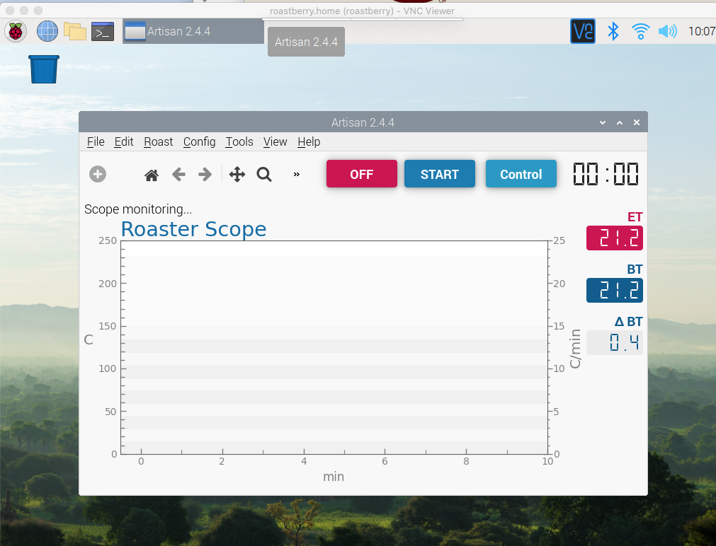
Thanks renatoa and greencardigan for your replies: I made it work for 2 sensors, connected 2 MAX6675 to the RP and adjusted the scripts as follows (concatenation of vars did not work out somehow): ... try: while 1: # read temperature connected at CS 22 et = max6675.read_temp(cs) bt = max6675.read_temp(cs2) # print temperatures print et print ',' print bt ser = serial.Serial('/dev/ttyAMA0') # open serial port #print(ser.name) # check which port was really used ser.write(et) # write a string ser.write(',') # write a string ser.write(bt) # write a string ser.close() # close port # when there are some errors with sensor, it return "-" sign and CS pin number # in this case it returns "-22" max6675.time.sleep(0.4) except KeyboardInterrupt: pass ... Now I get ET and BT readings within Artisan as expected. However, I have to leave in place both the serial and modbus-part, otherwise it does not work somehow, only the print statement is not enough. Thanks again and keep you posted! Regards
zamunda attached the following image:
|
|
|
|
| zamunda |
Posted on 07/01/2021 7:04 AM
|
|
1/4 Pounder Posts: 173 Joined: November 17, 2020 |
Hello I started playing with Events now, added a slider for Air Control and wrote a small test script: /home/pi/serial/air.py So at the Air-slider-> Call program: /home/pi/serial/air.py {} The test script logs the actual value of the slider to a file, so far, so good. Now, if I add "{~Y1} as a second argument, I supposed that this would write the ET to the file as well: /home/pi/serial/air.py {} {~Y1} However, it gives me an error: Exception: fireslideraction()'~Y1' Isn't this the proper way of passing BT as an argument to a program or script? Thanks in advance for any hint! #!/usr/bin/python import sys af = sys.argv[1] print sys.argv[1] et = sys.argv[2] print sys.argv[2] f = open("/home/pi/serial/air.txt", "a") f.write(af+",") f.write(et+"\r\n") f.close() |
|
|
|
| zamunda |
Posted on 07/06/2021 2:19 AM
|
|
1/4 Pounder Posts: 173 Joined: November 17, 2020 |
Hello, I have everything ready for show time: the Raspberry Pi, two thermocouples on the Pi measuring with Artisan, an Solid State realy for the heater and a (manual) DC control for the fan. Measuring temps works perfect but as soon as I start the fan in combination with the probes on the Pi, temps become unstable/unreliable. Somehow, there is an interaction between the probes and the DC-controller (has no ground). The solid state for the heater does not disturb the probes. Anyone seen this behaviour? Where does this come from? Is there a solution other than use a meter on the Pi instead of probes (MAX6675) directly on the Pi? A big thanks as usuual! Regards |
|
|
|
| greencardigan |
Posted on 07/07/2021 7:36 PM
|
|
1 1/2 Pounder Posts: 1185 Joined: November 21, 2010 |
Try grounding the roaster to the Pi ground? Try insulating the thermocouples from the roaster body? |
|
|
|
| zamunda |
Posted on 07/08/2021 2:29 AM
|
|
1/4 Pounder Posts: 173 Joined: November 17, 2020 |
Hello greencardigan, Thanks for your response, I'll try to insulate the probes from the chambers. I think my mistake was to completely remove the PCB when modifying the fan instead of leaving the capacitors and inductors in place as explained here: https://www.instructables.com/Arduino-controlled-DIY-Coffee-Roaster/ : "For my DC fan motor, I modified the PCB to connect this to the TC4+. Essentially, you want to remove the wires, AC capacitor, and bridge rectifier from the PCB, and connect new wires where the output of the bridge rectifier was. This way, we keep the inductors and capacitors around the fan motor, which are useful for filtering out noise. If you remove the PCB entirely and solder wires directly onto the motor terminals, you might have problems with electrical noise making its way down to the TC4+ and messing with your thermocouple readings (or worse)." But since I already removed it I will try if insulation helps! Thanks and regards |
|
|
|
| zamunda |
Posted on 07/14/2021 1:09 PM
|
|
1/4 Pounder Posts: 173 Joined: November 17, 2020 |
Hello, AC-relay control and probes work fine now, I would like to control the fan as well by means of the Raspberry Pi and Artisan. Therefore, I bought the L298N, quite cheap (7 euros): https://www.electronicshub.org/raspberry-pi-l298n-interface-tutorial-control-dc-motor-l298n-raspberry-pi/ I connected the fan, the board and a 12V DC for testing. This is the script I use (see below)... From the command line it works quite well (changing speed works as expected) but if I call it from the Event-manager from Artisan, I get mixed results...seems like subsequent commands get mixed so maybe I have to adjust the script, do not know yet... Any experience with this set-up? Thanks and regards, #!/usr/bin/python2.7 import RPi.GPIO as GPIO # Import GPIO module import time # Import time module from sys import argv ENA = 25 IN1 = 24 IN2 = 23 if __name__ == '__main__': try: # Initialization GPIO.setmode(GPIO.BCM) # Use BCM numbering method GPIO.setup(ENA, GPIO.OUT) # Set the GPIO pin corresponding to ENA to output mode GPIO.setup(IN1, GPIO.OUT) # Set the GPIO pin corresponding to IN1 to output mode GPIO.setup(IN2, GPIO.OUT) # Set the GPIO pin corresponding to IN2 to output mode freq = 500 startspeed = 0 pwm = GPIO.PWM(ENA, freq) # Set the input PWM pulse signal to ENA, the frequency is freq and create a PWM object pwm.start(startspeed) # Start inputting PWM pulse signal to ENA with the initial duty cycle of speed speed=int(argv[1]) # Set the motor to forward rotation GPIO.output(IN1, False) # Set IN1 to 0 GPIO.output(IN2, True) # Set IN2 to 1 pwm.ChangeDutyCycle(speed) # Change the PWM duty cycle time.sleep(100) finally: pwm.stop() # Stop PWM GPIO.cleanup() # Clean up and release GPIO resources, reset GPIO |
|
|
|
| zamunda |
Posted on 07/15/2021 3:12 AM
|
|
1/4 Pounder Posts: 173 Joined: November 17, 2020 |
Hello, Finally, I worked out a script for air-control which works with the Events for Artisan (sliders, buttons), see below... Script should be called like this fe: /home/pi/Roaster/Scripts/air-control.py {} [for using with a slider, dynamic value] /home/pi/Roaster/Scripts/air-control.py 35 [for using with a button, static value] Regards, #!/usr/bin/python3 import RPi.GPIO as GPIO # Import GPIO module import time # Import time module from sys import argv ENA = 25 IN1 = 24 IN2 = 23 def get_slidervalue(filepath): """ Returns the slidervalue as an int, read from the first line of filepath """ with open(filepath) as f: first_line = f.readline().strip() return int(first_line) if __name__ == '__main__': try: # read the slider value from argv speed = int(argv[1]) sliderfilepath = "/home/pi/Roaster/Scripts/airvalue.txt" # write the slider value to the file and close file sliderfile = open(sliderfilepath, "w") sliderfile.write(str(speed)) sliderfile.close() # Initialization GPIO.setmode(GPIO.BCM) # Use BCM numbering method GPIO.setup(ENA, GPIO.OUT) # Set the GPIO pin corresponding to ENA to output mode GPIO.setup(IN1, GPIO.OUT) # Set the GPIO pin corresponding to IN1 to output mode GPIO.setup(IN2, GPIO.OUT) # Set the GPIO pin corresponding to IN2 to output mode freq = 500 startspeed = 0 pwm = GPIO.PWM(ENA, freq) # Set the input PWM pulse signal to ENA, the frequency is freq and create a PWM object pwm.start(startspeed) # Start inputting PWM pulse signal to ENA with the initial duty cycle of speed # Set the motor to forward rotation, switch IN1 and IN2 to backward rotation if needed GPIO.output(IN1, False) # Set IN1 to 0 GPIO.output(IN2, True) # Set IN2 to 1 # while this file has the latest cycle value latestSpeed = True while latestSpeed: # check if this is not the newest process newestSpeed = get_slidervalue(sliderfilepath) if newestSpeed != speed: latestSpeed = False break # set fan to desired speed pwm.ChangeDutyCycle(speed) # Change the PWM duty cycle finally: pwm.stop() # Stop PWM GPIO.cleanup() # Clean up and release GPIO resources, reset GPIO |
|
|
|

Page 2 of 2: 12
| Jump to Forum: |
Similar Threads
| Thread | Forum | Replies | Last Post |
|---|---|---|---|
| Unable to get Artisan Scope's PID to control heating | Dataloggers/Controllers/Rate of Rise Meters | 4 | 08/01/2023 9:11 AM |
| Raspberry+artisan | Bread Machine Roasters | 8 | 03/08/2023 1:06 PM |
| Using a TC4 with Artisan Roaster Scope | Dataloggers/Controllers/Rate of Rise Meters | 41 | 05/09/2022 12:06 PM |
| TC4 connect to Raspberry Pi | Dataloggers/Controllers/Rate of Rise Meters | 55 | 01/04/2022 5:42 PM |
| How to get accurate temp readings | MY FIRST ROASTER | 5 | 01/07/2021 2:29 AM |
Powered by PHP-Fusion Copyright © 2024 PHP-Fusion Inc
Released as free software without warranties under GNU Affero GPL v3
Designed with ♥ by NetriXHosted by skpacman