
Login

Shoutbox
You must login to post a message.
renatoa
07/26/2024 3:49 PM
Bill grubbe and Jk, 
allenb
07/26/2024 5:15 AM
Spiderkw Welcome to HRO!

renatoa
07/24/2024 8:31 AM
ramiroflores and John123,

 ?
?
?renatoa
07/21/2024 1:18 AM
 , Luislobo
renatoa
07/19/2024 11:28 AM
Koepea,
Forum Threads
Newest Threads
Skywalker roaster modsBackground Roast Iss...
Hello from Arkansas
TC4ESP
Green coffee reviews
Hottest Threads
| Skywalker roaster... | [375] |
| TC4ESP | [115] |
| War on Farmers by... | [47] |
| Adventures in flu... | [26] |
| Hello! (soon) Roa... | [17] |
In Memory Of Ginny

Donations
Latest Donations
dmccallum - 10.00
JackH - 25.00
snwcmpr - 10.00
Anonymous - 2.00
Anonymous - 5.00
dmccallum - 10.00
JackH - 25.00
snwcmpr - 10.00
Anonymous - 2.00
Anonymous - 5.00
Users Online
Guests Online: 8
Members Online: 0
Total Members: 8,393
Newest Member: Bill grubbe
Members Online: 0
Total Members: 8,393
Newest Member: Bill grubbe
View Thread
Who is here? 1 guest(s)
 Testing Arduino UNO with bitwisetech / popc and MAX6675
|
|
| zamunda |
Posted on 08/06/2021 4:53 AM
|
 1/4 Pounder  Posts: 173 Joined: November 17, 2020 |
Hello, Would like to test my coffee roaster with Arduino UNO and MAX6675 sensors (I am new to Arduino). Managed to get the sensor working with an example sketch...also another example sketch for SSR. Then would like to implement this example: https://medium.co...a3334fd7d5 ...but this did not work, get Modbus communication errors despite a lot of tweaking the settings. So now I came across this sketch: https://github.co...etech/popc Seems to be configured per default for Arduino with MAX31855 sensors although I get the impression that it should also work with MAX6675. Anyone had success with this setup? Any idea/suggestion will be highly appreciated! Regards Edited by JackH on 08/06/2021 12:28 PM |
|
|
|
| renatoa |
Posted on 08/06/2021 5:50 AM
|
|
Administrator Posts: 3104 Joined: September 30, 2016 |
Worked some months in 2018 together with the author to make an ESP port of popc. Succeeded, good code and logic inside, but MAX circuits usage limits its capabilities, at least for my pickiness, so finally switched to TC4. |
|
|
|
| zamunda |
Posted on 08/06/2021 6:13 AM
|
|
1/4 Pounder Posts: 173 Joined: November 17, 2020 |
Hello Renatoa, Thanks for your reply...I am tempted to purchase a TC4+ which has "everything you need" on board. |
|
|
|
| renatoa |
Posted on 08/06/2021 7:33 AM
|
|
Administrator Posts: 3104 Joined: September 30, 2016 |
Or, if you are a builder, as your MAX experiments shows, have a look at my TC4ESP thread/project. TC4 heart with a smarter brain, full roast assistance without a computer tethered. |
|
|
|
| zamunda |
Posted on 08/07/2021 9:24 AM
|
|
1/4 Pounder Posts: 173 Joined: November 17, 2020 |
Hello, I am testing further with Arduino and the sketches I mentioned above. The one of Lukas: https://medium.co...a3334fd7d5 ...finally worked for me: by means of Modbus I get the BT within Artisan and with a SSR and slider I should be able to control the heater. However, the slider works a bit weird in my opinion (I checked by connecting a bulb to the relay: when I set the slider to fe '50' the bulb starts flickering, if I set it to '0' it stays on and if I set it to '100' it stays off. That is, the opposite of what I would expect: at '100' the heater ("bulb") should be at full capacity and at '0', it should be off completely. Is there an explaination for this "inverted" behaviour? Thanks in advance!
zamunda attached the following images:


Edited by renatoa on 08/07/2021 11:19 AM |
|
|
|
| renatoa |
Posted on 08/07/2021 11:37 AM
|
|
Administrator Posts: 3104 Joined: September 30, 2016 |
The way how he controls the power modulation is not right. The statement below in his code: Code Download source analogWrite(relay, (au16data[4]/100.0)*255); ... apparently should produce a right waveform, like in this image:  ... thus different duty cycle for various power levels sent via register 4. What is not right in the above approach is the frequency of pulses. To obtain such effect you need use long pulses, in the 1-2 seconds ballpark, for the on-off cycle. Instead, analogWrite command outputs a 490 Hz signal, which can't be used as is to control directly a SSR. Good for a DC power control using a MOSFET, but not for AC using a triac. |
|
|
|
| zamunda |
Posted on 08/07/2021 12:24 PM
|
|
1/4 Pounder Posts: 173 Joined: November 17, 2020 |
Hello Renatoa, Thanks for your detailed response...so if I understand you right, I could use this SSR for DC-power controlling the fan (if I add a MOSFET)...but how to control the heater with a SSR/MODBUS then ? In another setup, I do this with a python-script with a 1-second cycle: 70% heat = (70% ON, 30% OFF per second) but do not see how to achieve this here...And does this explain the "inverted" behaviour of the slider as mentioned? Any further suggestions? Thanks and regards, Edited by zamunda on 08/07/2021 12:41 PM |
|
|
|
| zamunda |
Posted on 08/07/2021 1:09 PM
|
|
1/4 Pounder Posts: 173 Joined: November 17, 2020 |
I think I found a (partial) answer here: https://www.home-barista.com/roasting/getting-artisan-to-talk-to-arduino-t58234.html |
|
|
|
| renatoa |
Posted on 08/07/2021 2:11 PM
|
|
Administrator Posts: 3104 Joined: September 30, 2016 |
There are many answers in that thread, no time to sieve all of them, so please point to a specific post, if you want to find if their solution is appropriate for your case. Please notice that some of the solutions in that thread are designed for 50 Hz mains. If you see delay(5) this means millisecond, and is the duration of 50 Hz quarter sine. There is not direct equivalent code for 60 Hz mains, because that time interval is not an integer number, but 4.1666(6)... milliseconds. For 60 Hz another loop logic is required. |
|
|
|
| zamunda |
Posted on 08/07/2021 2:16 PM
|
|
1/4 Pounder Posts: 173 Joined: November 17, 2020 |
Hello, Based on the answers in the thread, I came up with this which worked for me in Artisan, that is, no modbus error, BT is read and slider seems to work, however, need further testing: [Sorry for my ignorance but what is the difference between 50Hz and 60 Hz mains?] #include <max6675.h> #include <ModbusRtu.h> // data array for modbus network sharing uint16_t au16data[16] = { 0, 0, 0, 0, 0, 0, 0, 0, 0, 0, 0, 0, 0, 0, 1, -1 }; /** Modbus object declaration u8id : node id = 0 for master, = 1..247 for slave u8serno : serial port (use 0 for Serial) u8txenpin : 0 for RS-232 and USB-FTDI or any pin number > 1 for RS-485 */ Modbus slave(1, 0, 0); // this is slave @1 and RS-232 or USB-FTDI int thermoDO = 6; int thermoCS = 5; int thermoCLK = 4; MAX6675 thermocouple(thermoCLK, thermoCS, thermoDO); // declare variable for Arduino pin connected to solid state relay (SSR) int relay = 9; // declare variables for Arduino pins to power MAX: int vccPin = 3; int gndPin = 2; void setup() { slave.begin( 19200); // 19200 baud, 8-bits, even, 1-bit stop // use Arduino pins pinMode(relay, OUTPUT); pinMode(vccPin, OUTPUT); digitalWrite(vccPin, HIGH); pinMode(gndPin, OUTPUT); digitalWrite(gndPin, LOW); delay(500); } void loop() { //write current thermocouple value au16data[2] = ((uint16_t) thermocouple.readCelsius() * 100); //poll modbus registers slave.poll( au16data, 16 ); // heater control loop: for (int i = 1; i <= 99; i++) { if (i <= au16data[4]) digitalWrite(relay, HIGH); else digitalWrite(relay, LOW); delay(5); } delay(500); } |
|
|
|
| renatoa |
Posted on 08/08/2021 1:41 AM
|
|
Administrator Posts: 3104 Joined: September 30, 2016 |
I see an issue in the heater loop area, that code will never give you more than 50% effective power into the heater element. Also, the delay(5) statement is for 50 Hz mains, else the results will be random, if you mount a bulb instead heater you should see flickering. I would replace this part: Code Download source // heater control loop: with... Code Download source digitalWrite(relay, HIGH); This change should give you full 0-100% range control, and not dependent on mains frequency. |
|
|
|
| zamunda |
Posted on 08/08/2021 2:59 AM
|
|
1/4 Pounder Posts: 173 Joined: November 17, 2020 |
Hello Renatoa, Thanks for your reply and the improved snippet for the heat control, I just tested it and it works as expected (with bulb for now, will connect later to roaster). Works perfect, thanks! I understand now what you mean with 50Hz vs 60Hz mains. Also discovered that I had not connected the SSR correctly to the board: GND board should go to the "-" of the SSR, and PIN 9 of Arduino to the "+" of the SSR. Now works as expected, big thanks! Post again here the updated version of the sketch: Code Download source #include <max6675.h> |
|
|
|
| renatoa |
Posted on 08/08/2021 10:25 AM
|
|
Administrator Posts: 3104 Joined: September 30, 2016 |
Actually, this code is just better, not perfect. To improve it even further we need to know the duration of temperature acquisition (readCelsius), and the ModBus polling. These time intervals aren't negligible, in the 250-300 ms ballpark, and the effect of ignoring them is an effective duty cycle lower than the desired power percent you send the command from Artisan. The error is about 20%, thus 100% sent from Artisan will mean 80% real heater power. If your heating requirements will never exceed 80% HTR level, then you could be fine even with this solution. Just be aware there is an issue ticking, that could turn in a problem if one day you want more power. |
|
|
|
| zamunda |
Posted on 08/09/2021 2:24 AM
|
|
1/4 Pounder Posts: 173 Joined: November 17, 2020 |
Hello Renatoa, Thanks for this! Today I tested this modbus-setup with a roaster and it worked quite well though I will do further testing later to confirm. How could I determine/set the values for temperature acquisition and the ModBus polling? And finally, if I would like to control also airflow of the DC-fan by means of a slider, what would be needed for that? In another setup, I configured the L293N module on a Raspberry Pi to enable fancontrol with a Python script and Artisan slider/buttons (https://www.youtube.com/watch?v=2bganVdLg5Q). This works but I get some strange behaviour during the roast: after 1-2minutes, speed seems to drop spontaneously or stop completely. Maybe there is a flaw in my script. Also, the L293N has a 2A max per outlet, one could possibly set 2 outlet ins paralel to get a 4A max? I read that fans consume a lot of current specially during start. In short: if I would like to control also airflow of the DC-fan with Arduino/Modbus, would the L293N module appropiate or is other hardware needed? Thanks again for any advice on this! Edited by zamunda on 08/09/2021 2:58 AM |
|
|
|
| renatoa |
Posted on 08/09/2021 4:25 AM
|
|
Administrator Posts: 3104 Joined: September 30, 2016 |
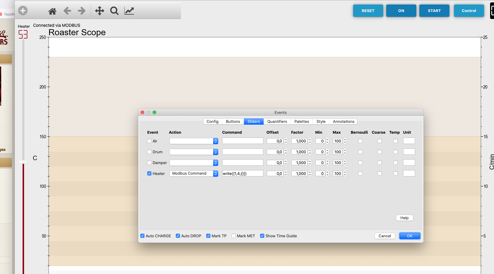
To transmit Fan slider values from Artisan to your board via ModBus you could allocate to Fan the register 5, and duplicate in Events dialog the write() command you have now for heater, but using register 5 instead 4, for the Air event. Check attached image. Then, in your main loop code place a statement as below: Code Download source analogWrite(fan, (au16data[5]/100.0)*255); ... to send control PWM to L293N. Fan is an output pin your choice, must be declared in setup() same way is the relay pin. Code Download source int relay = 9; To avoid big current issue, check how is DCFAN slew command implemented in TC4, applying changes in small 5% steps, even if you jump from 0 to 100%.
renatoa attached the following image:

|
|
|
|
| zamunda |
Posted on 08/09/2021 1:26 PM
|
|
1/4 Pounder Posts: 173 Joined: November 17, 2020 |
Hello Renatoa, Thanks for explaining how to work with the fan and MODBUS. I did a quick test with a separate fan and this works... Only thing I noticed is that the fan reacts only after 2-3 seconds when moving the air slider... This is the sketch I have used right now (see below), tomorrow I will test it with a roaster... Also will try to look into the TC4 code regarding the big current issue. A big thanks again and I'll keep you posted! Code Download source #include <max6675.h>
zamunda attached the following images:


Edited by zamunda on 08/09/2021 1:37 PM |
|
|
|
| zamunda |
Posted on 08/09/2021 1:28 PM
|
|
1/4 Pounder Posts: 173 Joined: November 17, 2020 |
Hello, Added some pics to previous post... Edited by zamunda on 08/09/2021 4:05 PM |
|
|
|
| renatoa |
Posted on 08/10/2021 4:36 AM
|
|
Administrator Posts: 3104 Joined: September 30, 2016 |
The slew fan logic is here, at line 406: https://github.co...reader.cpp target is the final speed you want to reach this routine should be called in the main loop, after any fan speed change, until target reached. |
|
|
|
| miyankizu |
Posted on 08/10/2021 4:54 AM
|
|
Newbie  Posts: 10 Joined: August 10, 2021 |
@renatoa @zamunda. I registered this forum because of your support each other. Personally I thank you , also I?m using same arduino sketch for my popper. Also realized that blink issue on the bulb on my trials. I?m not familiar with arduino programming but the sketch I have used before may give an idea to also to control with Artisan. The guy from Portuguese has written this code to control his whole system with roastlogger. I tried this system but because of roastlogger doesn?t update for a long time, I want to change it with Artisan. And you are developing this system with fan control wow  I wish the sketch will also helps I wish the sketch will also helps https://medium.co...88ac60a37b @zamunda is possible to share motor shield and arduino connection on basic drawing. Edited by renatoa on 08/10/2021 6:03 AM |
|
|
|
| renatoa |
Posted on 08/10/2021 6:07 AM
|
|
Administrator Posts: 3104 Joined: September 30, 2016 |
Before making the things too complicate, may I ask what's the point of fan control through Artisan ? |
|
|
|
| miyankizu |
Posted on 08/10/2021 6:14 AM
|
|
Newbie Posts: 10 Joined: August 10, 2021 |
Quote renatoa wrote: Before making the things too complicate, may I ask what's the point of fan control through Artisan ? Actually I didn?t want to mix the thing I just want to thank both of you and sharing another source that may help about fan control. Personally I prefer manual control on fan according to my experiences. Sorry if I disturb |
|
|
|
| renatoa |
Posted on 08/10/2021 6:27 AM
|
|
Administrator Posts: 3104 Joined: September 30, 2016 |
No worries, no disturbance. The question is open, anyone having an answer can share his thoughts. |
|
|
|
| zamunda |
Posted on 08/10/2021 7:19 AM
|
|
1/4 Pounder Posts: 173 Joined: November 17, 2020 |
Hello Renatoa, Thanks for this pointer! I understand from these lines that I have to build the logic based on target value and current value. I guess that "target = (au16data[5] / 100.0) * 255)" but how can I get the current value from Artisan back so I can compare it with the target and build the steps based on their difference? Hope you get my point. Thanks in advance! Quote renatoa wrote: The slew fan logic is here, at line 406: https://github.co...reader.cpp target is the final speed you want to reach this routine should be called in the main loop, after any fan speed change, until target reached. |
|
|
|
| renatoa |
Posted on 08/10/2021 8:31 AM
|
|
Administrator Posts: 3104 Joined: September 30, 2016 |
current is a variable you keep in your sketch, not taken from Artisan. And target is the value from ModBis register 5, you guessed right, when slider from Artisan move, the new value will be sent via ModBus to you. The slew logic will compare the current fan speed value with new target, and, if different, will increase/decrease current variable value by slew step. The new current value will be sent to fan control circuit. Edited by renatoa on 08/11/2021 6:06 AM |
|
|
|
| zamunda |
Posted on 08/10/2021 8:32 AM
|
|
1/4 Pounder Posts: 173 Joined: November 17, 2020 |
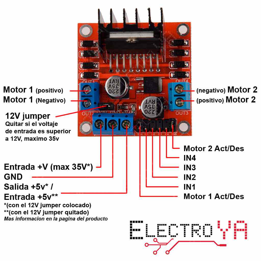
Quote @zamunda is possible to share motor shield and arduino connection on basic drawing. Will be happy to share the connections. In fact, i did it according the enclosed diagram, leaving out the connections for the second motor AND leaving the 12V jumper in place. I have some doubts about the way I connected it (though it is working  ). ).The fan is driven with a 18V DC power supply and so according the specs I have to remove the 12V jumper. However, if I do that, it does not work so I have to look into that. Besides, I use this board only for testing but I think this is a very old motor driver board and I doubt whether it can be used in a "production environment"... If anyone could advice on a better alternative (maybe the MD10C?) I would be gratefull! Thanks and regards,
zamunda attached the following image:
Edited by zamunda on 08/10/2021 8:44 AM |
|
|
|

| Jump to Forum: |
Powered by PHP-Fusion Copyright © 2024 PHP-Fusion Inc
Released as free software without warranties under GNU Affero GPL v3
Designed with ♥ by NetriXHosted by skpacman