
Login

Shoutbox
You must login to post a message.
renatoa
07/26/2024 3:49 PM
Bill grubbe and Jk, 
allenb
07/26/2024 5:15 AM
Spiderkw Welcome to HRO!

renatoa
07/24/2024 8:31 AM
ramiroflores and John123,

 ?
?
?renatoa
07/21/2024 1:18 AM
 , Luislobo
renatoa
07/19/2024 11:28 AM
Koepea,
Forum Threads
Newest Threads
Skywalker roaster modsBackground Roast Iss...
Hello from Arkansas
TC4ESP
Green coffee reviews
Hottest Threads
| Skywalker roaster... | [375] |
| TC4ESP | [115] |
| War on Farmers by... | [47] |
| Adventures in flu... | [26] |
| Hello! (soon) Roa... | [17] |
In Memory Of Ginny

Donations
Latest Donations
dmccallum - 10.00
JackH - 25.00
snwcmpr - 10.00
Anonymous - 2.00
Anonymous - 5.00
dmccallum - 10.00
JackH - 25.00
snwcmpr - 10.00
Anonymous - 2.00
Anonymous - 5.00
Users Online
Guests Online: 5
Members Online: 0
Total Members: 8,393
Newest Member: Bill grubbe
Members Online: 0
Total Members: 8,393
Newest Member: Bill grubbe
View Thread
Who is here? 1 guest(s)
 Testing Arduino UNO with bitwisetech / popc and MAX6675
|
|
| renatoa |
Posted on 08/23/2021 6:00 AM
|
|
Administrator Posts: 3104 Joined: September 30, 2016 |
An error occured during modbus reading or decoding. Check modbusport.py, in 2.4.x src\artisanlib folder |
|
|
|
| zamunda |
Posted on 08/24/2021 8:42 AM
|
 1/4 Pounder  Posts: 173 Joined: November 17, 2020 |
Quote renatoa wrote: An error occured during modbus reading or decoding. Check modbusport.py, in 2.4.x src\artisanlib folder Thanks for your reply. I am on Mac OS x and can't find such a folder. I am a bit lost: I tried several configs also this from: https://www.home-barista.com/roasting/getting-artisan-to-talk-to-arduino-t58234-20.html Behaviour is the same for all of them, over USB, temp is read and passed to Artisan, no problem, once connected over BT, I get the Modbus error, that is, RX = none. I am quite sure the BT is ok, did several tests via basic scripts and I can communicate over BT from the module to me laptop. Is there another point I am missing here maybe? Over BT I power Arduino via USB to an iPhone adapter (5V, 1A). Could that be critical? Should I power Arduino by the dedicated power inlet and not over USB? Any other suggestions are welcome! Thanks |
|
|
|
| zamunda |
Posted on 08/25/2021 12:25 PM
|
|
1/4 Pounder Posts: 173 Joined: November 17, 2020 |
Hello, Finally, I achieved to connect over Modbus/Bluetooth, I had to change the sketch by assigning PINs to RX/TX other than the dedicated PINs on the Arduino and use SoftwareSerial. The following sketch worked for me: Code Download source
|
|
|
|
| zamunda |
Posted on 09/10/2021 9:45 AM
|
|
1/4 Pounder Posts: 173 Joined: November 17, 2020 |
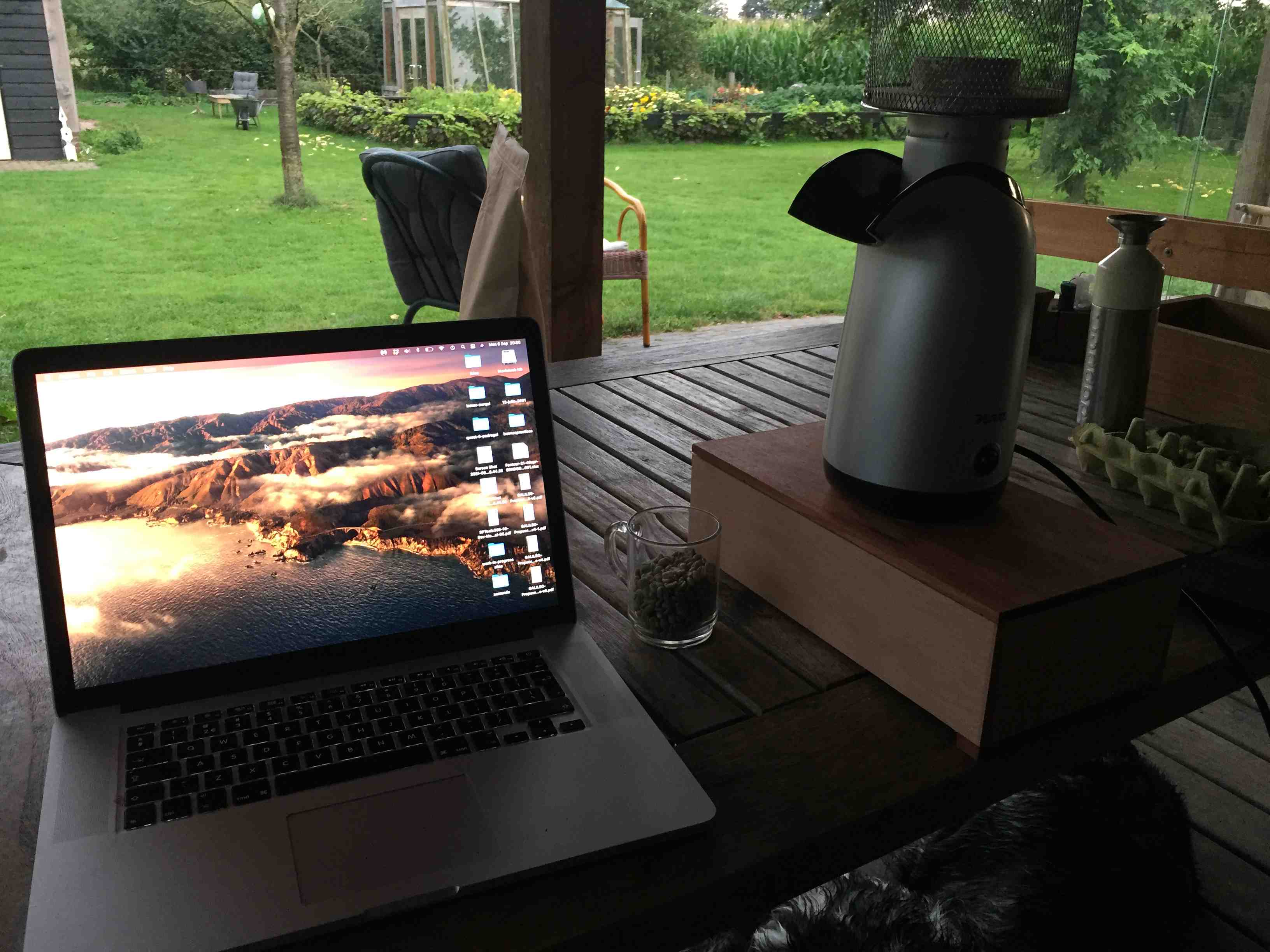
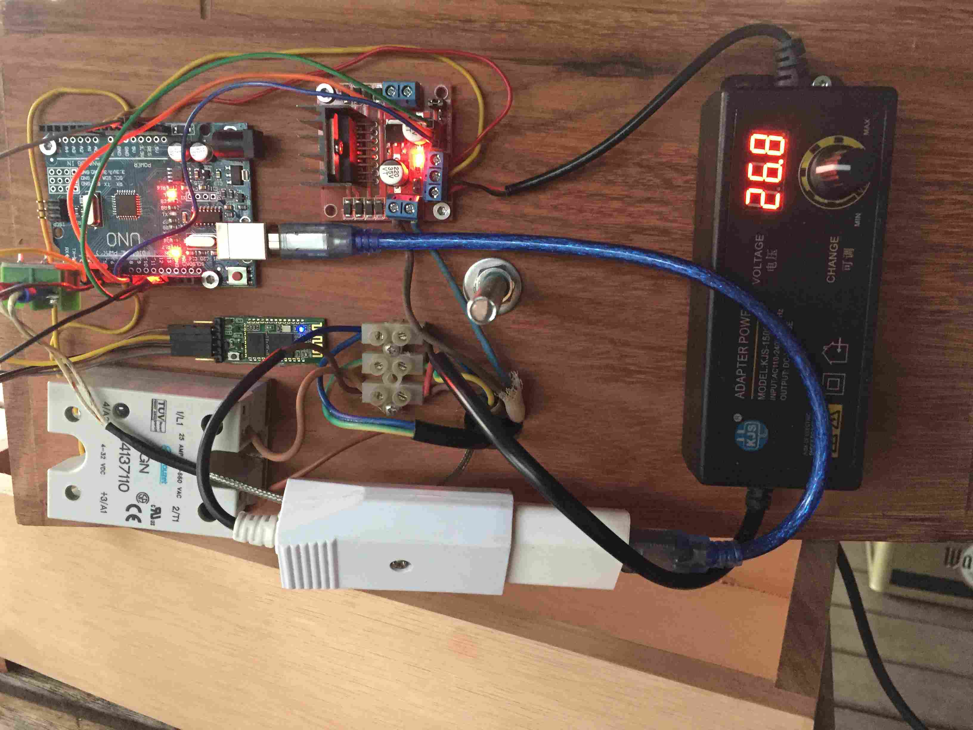
Hello, Based on the sketch above, I did some roasting with batches of 100gram. I think the result comes out quite nice, from Artisan I can control heat and air conveniently. I mounted the roaster on a wooden box which I can open later to check wirings etc. Bluetooth also works well. Also built a simple chaff collector which sits on top of the roaster which can be emptied from time to time. BTW: I disabled the "slew-function" withing the sketch for now since this "messed up" de loop-functionality within Arduino. So far, I did not experience overload problems (which was something this function should help to prevent) Obviously there is much room for improvement but this was/is an (exciting) learning-by-doing-and-falling process. Hardware used in this build: - Princess Popcorn popper (1200W/220V) - MAX6675 sensor for temp readings - Arduino UNO (3) - (Manual) DC voltage adapter for fan - L298N DC-Motor Controller for slider-controlling the fan from Artisan - Solid state relay for controlling the heat element - Bluetooth module HC06 for wireless connection from Artisan to roaster - DC-adapter iPhone for Arduino Big thanks to everyone on this forum, if you have any questions/suggestions, please let me know. Quote zamunda wrote: Hello, Finally, I achieved to connect over Modbus/Bluetooth, I had to change the sketch by assigning PINs to RX/TX other than the dedicated PINs on the Arduino and use SoftwareSerial. The following sketch worked for me: Code Download source
zamunda attached the following images:


Edited by zamunda on 09/10/2021 10:26 AM |
|
|
|
| renatoa |
Posted on 09/10/2021 12:58 PM
|
|
Administrator Posts: 3104 Joined: September 30, 2016 |
Congrats ! Actually, the slew feature can be implemented human side, being careful to not move the Artisan slider in big steps. All you have to do is to refrain handling the fan slider with the mouse, is the only way to jump from 0 to 100% in a single step. With the keyboard, and up/down keys, the slider steps in small increments, even finer than the slew step from software solution. With a bit of discipline, it could become a habit. |
|
|
|
| zamunda |
Posted on 09/11/2021 2:19 AM
|
|
1/4 Pounder Posts: 173 Joined: November 17, 2020 |
Hello Renatoa, Thanks for your reply and tip on using the keyboard, wasn't aware of this, tried it and is indeed very handy! Another potential risk with modded popcorn machines is that if you leave the heater on for some reason without running the fan, after 5-10 seconds the coil burns the fan housing or worse. This happened to me once and I guess I am not the only one  Is there a way to prevent this? I thought of adding a condition in the void loop: "if value from fan slider >50 { start heater } else { ... }" But I do not know whether this is good practice? Or are there other common solutions (besides from paying attention while roasting)? Regards! Edited by zamunda on 09/11/2021 10:38 AM |
|
|
|
| renatoa |
Posted on 09/11/2021 11:58 AM
|
|
Administrator Posts: 3104 Joined: September 30, 2016 |
Yep, this is the logic in TC4 too... For any attempt to change heater level, the check below: Code Download source if (FAN_DUTY < HTR_CUTOFF_FAN_VAL) {And reciprocal, when fan change attempt... Code Download source if( pac_level < HTR_CUTOFF_FAN_VAL ) { // if new levelOT2 < cutoff value then turn off OT1 |
|
|
|
| zamunda |
Posted on 09/12/2021 9:01 AM
|
|
1/4 Pounder Posts: 173 Joined: November 17, 2020 |
Hello Renatoa, Thank you for this snippet, I rewrote my sketch like this based on that: Code Download source // Define minimal airflow setting Does this make sense? Within TC, there is a var "FAN_DUTY" which holds the ACTUAL value of the fan, however, within my project, I do not know whether/how this value is stored or can be obtained from Artisan. I only know of the DESIRED value which is "au16data[5]". Am I right here? Thanks! |
|
|
|
| renatoa |
Posted on 09/13/2021 2:11 PM
|
|
Administrator Posts: 3104 Joined: September 30, 2016 |
Why are you operating changes on fan before the modbus poll and not after ? This way you introduce one second delay between the slider change and fan speed change... without any benefit I can detect. |
|
|
|
| miyankizu |
Posted on 09/27/2021 8:19 AM
|
|
Newbie  Posts: 10 Joined: August 10, 2021 |
Quote zamunda wrote: Hello, Based on the sketch above, I did some roasting with batches of 100gram. I think the result comes out quite nice, from Artisan I can control heat and air conveniently. I mounted the roaster on a wooden box which I can open later to check wirings etc. Bluetooth also works well. Also built a simple chaff collector which sits on top of the roaster which can be emptied from time to time. BTW: I disabled the "slew-function" withing the sketch for now since this "messed up" de loop-functionality within Arduino. So far, I did not experience overload problems (which was something this function should help to prevent) Obviously there is much room for improvement but this was/is an (exciting) learning-by-doing-and-falling process. Hardware used in this build: - Princess Popcorn popper (1200W/220V) - MAX6675 sensor for temp readings - Arduino UNO (3) - (Manual) DC voltage adapter for fan - L298N DC-Motor Controller for slider-controlling the fan from Artisan - Solid state relay for controlling the heat element - Bluetooth module HC06 for wireless connection from Artisan to roaster - DC-adapter iPhone for Arduino Big thanks to everyone on this forum, if you have any questions/suggestions, please let me know. Quote zamunda wrote: Hello, Finally, I achieved to connect over Modbus/Bluetooth, I had to change the sketch by assigning PINs to RX/TX other than the dedicated PINs on the Arduino and use SoftwareSerial. The following sketch worked for me: Code Download source
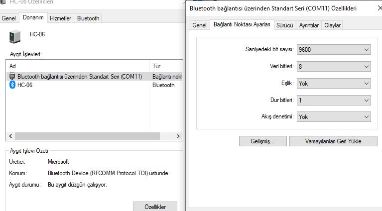
hello zamunda , renatoa I appriciate for your effort. I also try to apply for solutions to my system. Also I have get modbus connection problem. when I check connection baudrate for HC-06 it has written as 9600 and I am not able to change it. I tried another solution to change baudrate in skecth as "9600" instead of "19200". Do you have any solution for it ?
miyankizu attached the following image:
|
|
|
|
| zamunda |
Posted on 09/27/2021 8:36 AM
|
|
1/4 Pounder Posts: 173 Joined: November 17, 2020 |
Hello, I just recently how to work with Arduino and how to change baudrates of the HC-06 so I am not that experienced but this video helped me a lot In short, you have to connect the RX and TX-pins of the HC-06 to the TX and RX-pin of the Arduino. Then go to the serial monitor of the IDE and send fe the command 'AT'...it should respond with 'OK' If you do not get a response you have to tweak settings: - set baudrate of serial monitor to '9600' if you have not changed initital rate of HC-06 - set "No line ending" in the serial monitor as well - interchange RX and TX connection cables from HC-06 to Arduino and try again... Once you get an 'OK' you can change baudrate with command 'AT+BAUD5' if I recall well. As said, the mentioned video was very helpfull for me. Hope this helps! Regards |
|
|
|
| miyankizu |
Posted on 09/27/2021 9:23 AM
|
|
Newbie Posts: 10 Joined: August 10, 2021 |
Quote zamunda wrote: Hello, I just recently how to work with Arduino and how to change baudrates of the HC-06 so I am not that experienced but this video helped me a lot In short, you have to connect the RX and TX-pins of the HC-06 to the TX and RX-pin of the Arduino. Then go to the serial monitor of the IDE and send fe the command 'AT'...it should respond with 'OK' If you do not get a response you have to tweak settings: - set baudrate of serial monitor to '9600' if you have not changed initital rate of HC-06 - set "No line ending" in the serial monitor as well - interchange RX and TX connection cables from HC-06 to Arduino and try again... Once you get an 'OK' you can change baudrate with command 'AT+BAUD5' if I recall well. As said, the mentioned video was very helpfull for me. Hope this helps! Regards thank you very much , I will check and if I found which works for me , I will update this topic |
|
|
|
| miyankizu |
Posted on 09/27/2021 9:26 AM
|
|
Newbie Posts: 10 Joined: August 10, 2021 |
Updated info : I changed my skecth again 19200 to 9600 and make same updates on MODBUS connection also in Artisan. And changed jumper cables in case of any problem. Now it works it reads values well. I haven't test it with popper , till now it goes good. Thanks to zamunda and renatoa  |
|
|
|
| zamunda |
Posted on 10/06/2021 12:34 PM
|
|
1/4 Pounder Posts: 173 Joined: November 17, 2020 |
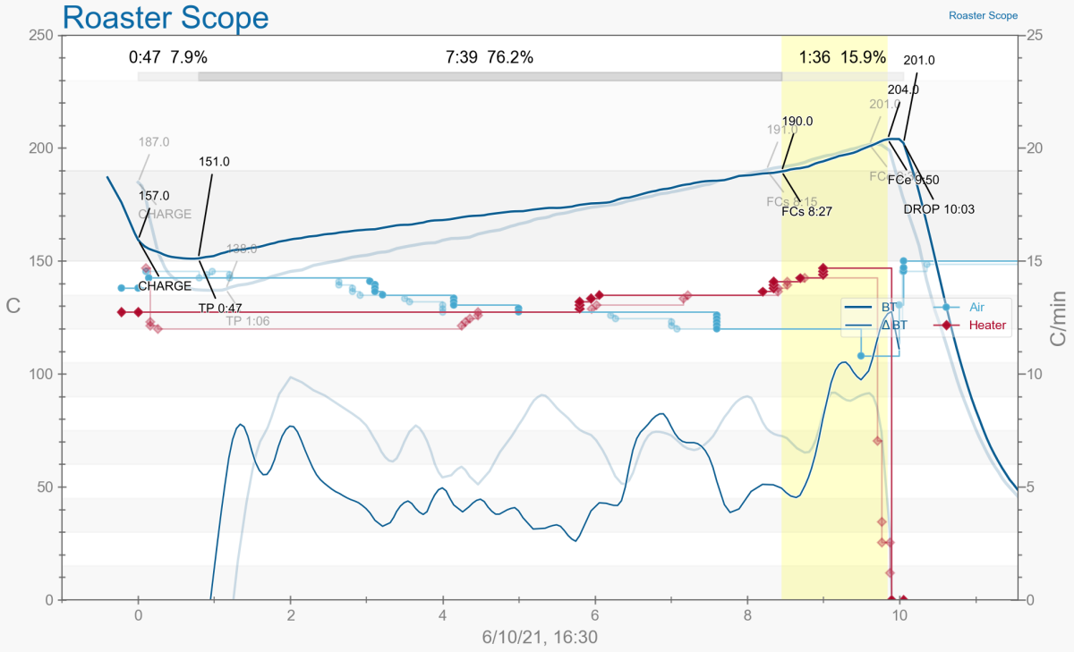
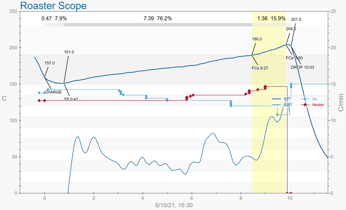
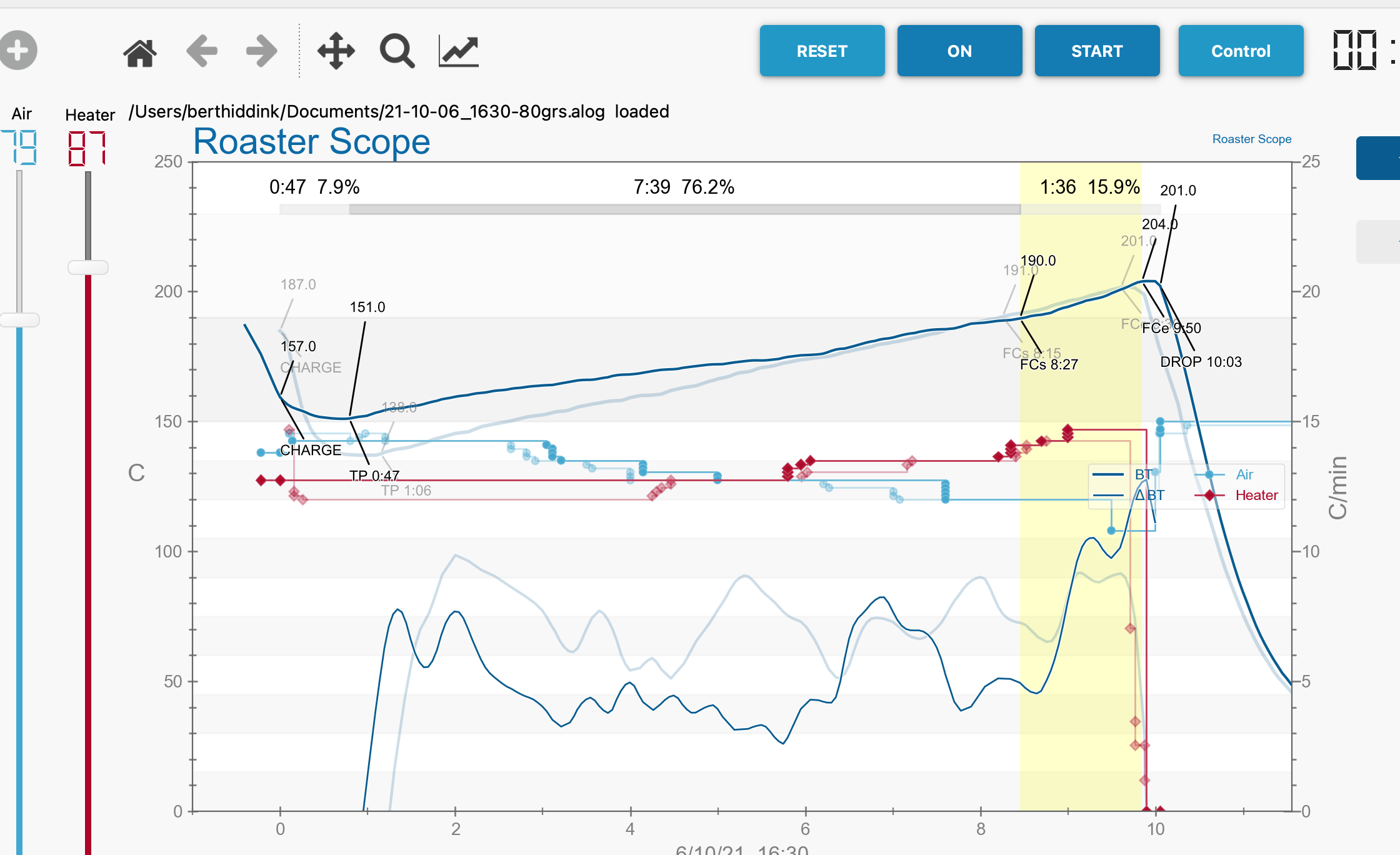
Hello, Showing some results from Artisan.... I roasted 80grs and 100 grs today playing with Air and Heater...works quite well technically I think...Normally I start with full air and 80% heat and after 3-4 minutes I lower the air a bit and increase some heat. Depending on ambiente temperature, I get first crack at 6-8 minutes, then leave the beans a minute after FC and finally cool them down in the roaster, cooling down to 30-40 degrees goes quite fast (< 1min). Happy with the result so far...Any comments are highly appreciated! Did a quick test with PID control but got quite confused with so many parameters to set, in fact, do not know how to start there... The settings shown in the image copied them from another project without really understanding how it works Could some of you help me a bit in explaining the basic concept of PID-control? Thanks!
zamunda attached the following images:

Edited by zamunda on 10/06/2021 12:42 PM |
|
|
|
| miyankizu |
Posted on 10/07/2021 1:46 AM
|
|
Newbie Posts: 10 Joined: August 10, 2021 |
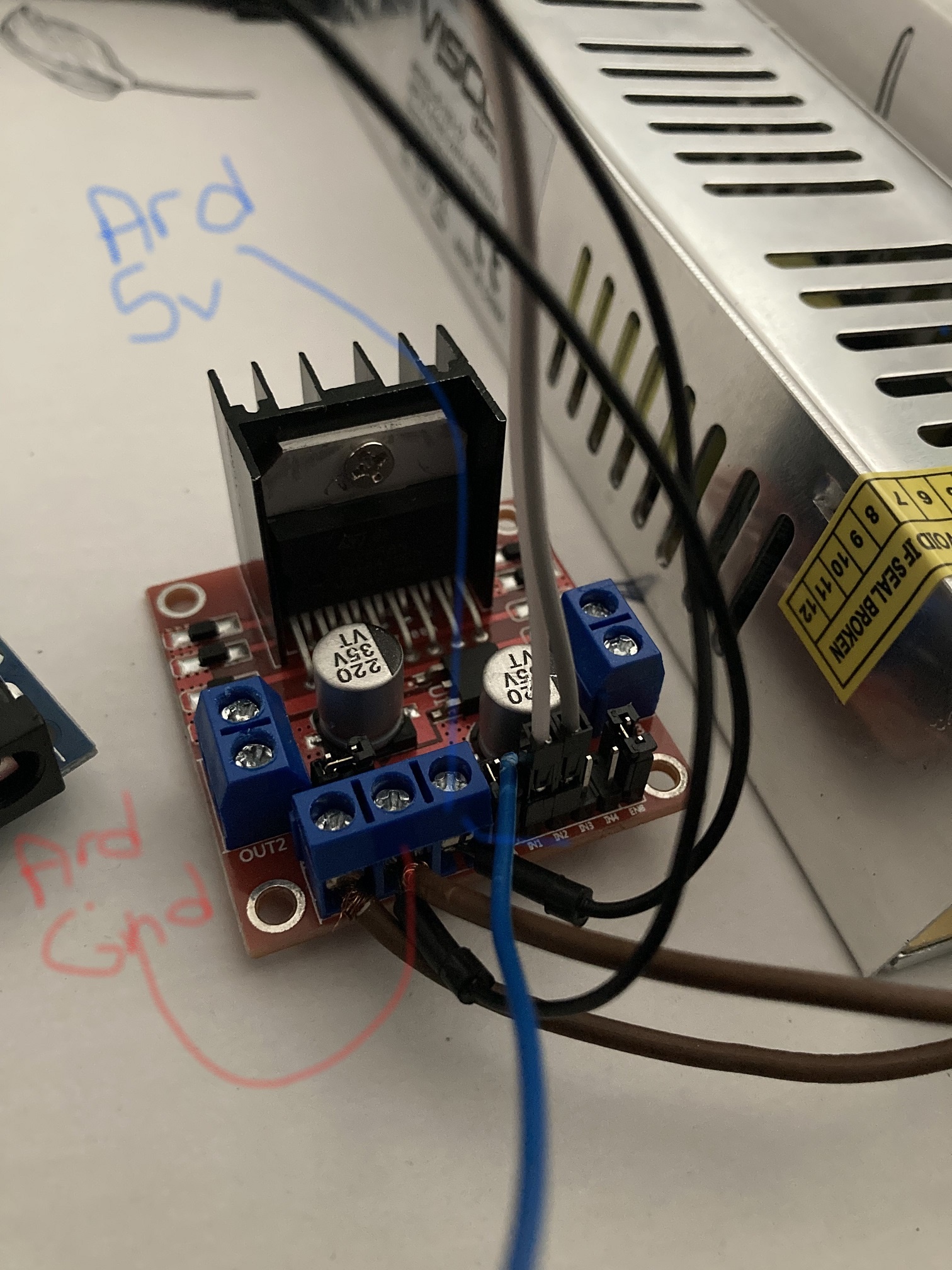
It is nice to hear that well done  I think you can roast more grams by chaning your power supply of fan. Also adding a tin can at the top of chamber. Because I can swirl 150 grams in my system with 24v 5A. I think you can roast more grams by chaning your power supply of fan. Also adding a tin can at the top of chamber. Because I can swirl 150 grams in my system with 24v 5A.By the way I built up your system. I can read temperature , but I'm not able to give a control from Artisan. I'm not sure that I can send the data to L298N from Arduino. Can you please share your circuit connection. I try to make my connections over your sketch and picture as I can see Here is my circuit. Quote zamunda wrote: Hello, Showing some results from Artisan.... I roasted 80grs and 100 grs today playing with Air and Heater...works quite well technically I think...Normally I start with full air and 80% heat and after 3-4 minutes I lower the air a bit and increase some heat. Depending on ambiente temperature, I get first crack at 6-8 minutes, then leave the beans a minute after FC and finally cool them down in the roaster, cooling down to 30-40 degrees goes quite fast (< 1min). Happy with the result so far...Any comments are highly appreciated! Did a quick test with PID control but got quite confused with so many parameters to set, in fact, do not know how to start there... The settings shown in the image copied them from another project without really understanding how it works Could some of you help me a bit in explaining the basic concept of PID-control? Thanks!
miyankizu attached the following images:

|
|
|
|
| zamunda |
Posted on 10/07/2021 4:32 AM
|
|
1/4 Pounder Posts: 173 Joined: November 17, 2020 |
Hello Yesterday I created a project on Github to make sharing easier: https://github.co...daroaster/ Haven't uploaded a circuit though but will try to do that shortly. What is it that you can not control from Artisan? Have you created a slider for both heater and air? Maybe you could download the settings from the Artisan folder and load these into yours and see how I have configured things (obviously adjust it according your setup, USB or BT, etc): https://github.co...in/artisan Hope this helps for now... |
|
|
|
| zamunda |
Posted on 12/04/2021 5:47 PM
|
|
1/4 Pounder Posts: 173 Joined: November 17, 2020 |
Hello, Updated the sketch for this project (with a big help of a friend) since I felt this could be done more efficiently within the loop separating controls for air, temperature and heater. Within the previous version, delays for air and temperature depended on the heater-delay. Did some roasts with this setup and there is evidently less delay in response when moving sliders within Artisan for air, also temp changes are shown at a higher frequency. https://github.co...Heater.ino Please let me know if you have any comments. Regards, Bert ########################
### A lot can happen over coffee ### ######################## |
|
|
|
| zamunda |
Posted on 12/05/2021 8:16 AM
|
|
1/4 Pounder Posts: 173 Joined: November 17, 2020 |
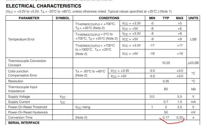
Hello, In order to test the minimal 'delay' (=conversion time) for the MAX6675 to be set within the loop, I added a temporary slider within Artisan. Its value is send to Arduino, this way I could determine by increasing/diminishing airflow that using '200ms' is still ok, '150ms' freezes the temperature showing within Artisan... '20' = 200ms '15' = 150ms etc.
zamunda attached the following image:
Edited by zamunda on 12/05/2021 8:24 AM ########################
### A lot can happen over coffee ### ######################## |
|
|
|
| renatoa |
Posted on 12/05/2021 8:31 AM
|
|
Administrator Posts: 3104 Joined: September 30, 2016 |
Chip specs say 250 ms, better stay on the safe side. |
|
|
|
| Golfkung |
Posted on 04/11/2023 8:46 AM
|
|
Newbie Posts: 4 Joined: April 08, 2023 |
Help me please. I follow coding reference below. and I big thank first. But I found problem from this .Please refer tu attached figure for my problem. Quote zamunda wrote: Hello Renatoa, Thanks for explaining how to work with the fan and MODBUS. I did a quick test with a separate fan and this works... Only thing I noticed is that the fan reacts only after 2-3 seconds when moving the air slider... This is the sketch I have used right now (see below), tomorrow I will test it with a roaster... Also will try to look into the TC4 code regarding the big current issue. A big thanks again and I'll keep you posted! Code Download source #include <max6675.h> Edited by Golfkung on 04/11/2023 9:08 AM |
|
|
|
| renatoa |
Posted on 04/11/2023 8:48 AM
|
|
Administrator Posts: 3104 Joined: September 30, 2016 |
Which figure ? You only quoted a post... |
|
|
|
| Golfkung |
Posted on 04/11/2023 9:19 AM
|
|
Newbie Posts: 4 Joined: April 08, 2023 |
Quote I have alreaady attached picture. |
|
|
|
| Golfkung |
Posted on 04/11/2023 10:06 AM
|
|
Newbie Posts: 4 Joined: April 08, 2023 |
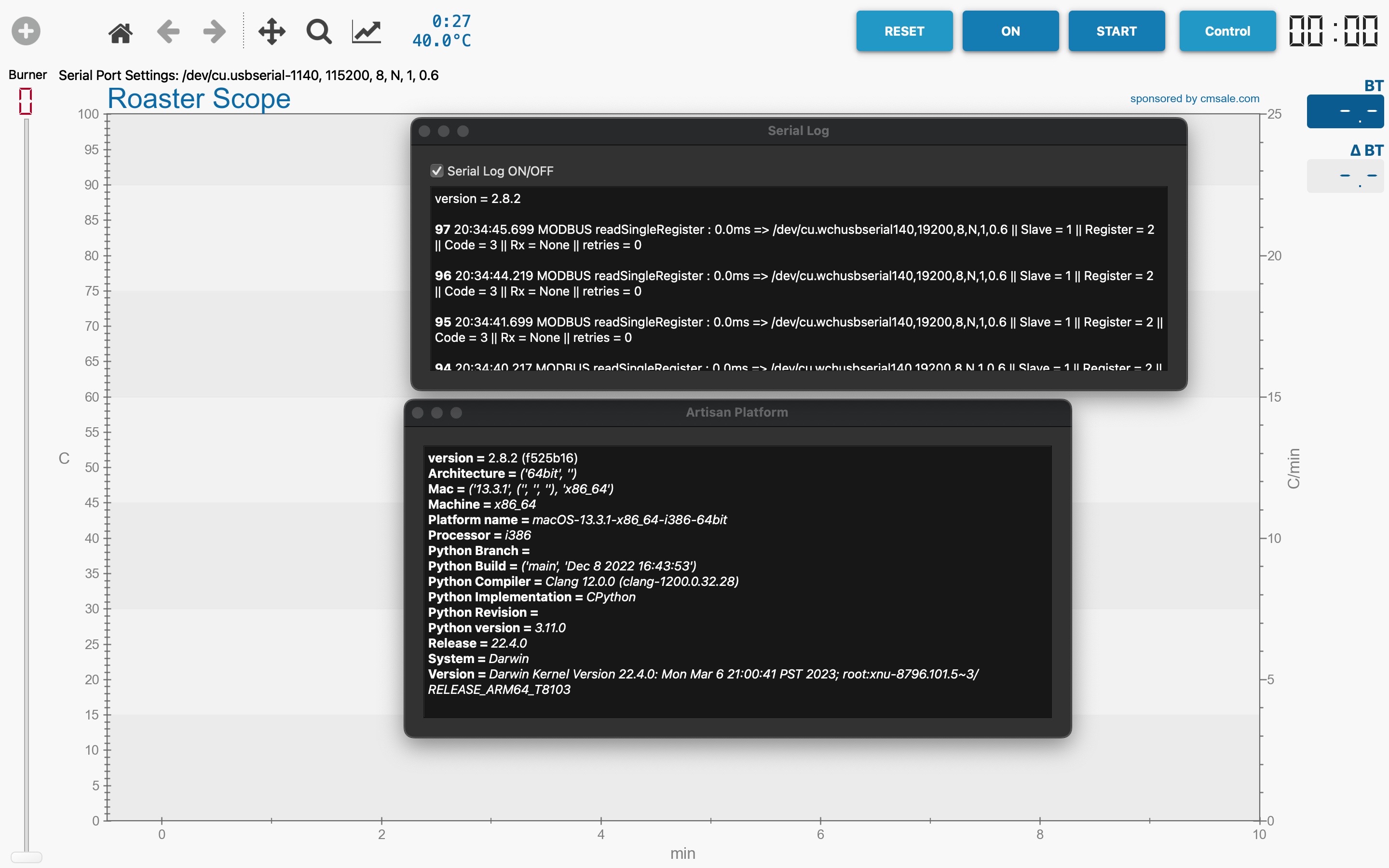
Quote For serial log====> version = 2.8.2 24 22:02:29.027 MODBUS readSingleRegister : 0.0ms => /dev/cu.wchusbserial140,19200,8,N,1,0.6 || Slave = 1 || Register = 2 || Code = 3 || Rx = None || retries = 0 ================================================================================f For Artisan platdorm version = 2.8.2 (f525b16) Architecture = ('64bit', '') Mac = ('13.3.1', ('', '', ''), 'x86_64') Machine = x86_64 Platform name = macOS-13.3.1-x86_64-i386-64bit Processor = i386 Python Branch = Python Build = ('main', 'Dec 8 2022 16:43:53') Python Compiler = Clang 12.0.0 (clang-1200.0.32.28) Python Implementation = CPython Python Revision = Python version = 3.11.0 Release = 22.4.0 System = Darwin Version = Darwin Kernel Version 22.4.0: Mon Mar 6 21:00:41 PST 2023; root:xnu-8796.101.5~3/RELEASE_ARM64_T8103 |
|
|
|
| Golfkung |
Posted on 04/11/2023 11:21 PM
|
|
Newbie Posts: 4 Joined: April 08, 2023 |
Quote Golfkung wrote: Quote For serial log====> version = 2.8.2 24 22:02:29.027 MODBUS readSingleRegister : 0.0ms => /dev/cu.wchusbserial140,19200,8,N,1,0.6 || Slave = 1 || Register = 2 || Code = 3 || Rx = None || retries = 0 ================================================================================f For Artisan platdorm version = 2.8.2 (f525b16) Architecture = ('64bit', '') Mac = ('13.3.1', ('', '', ''), 'x86_64') Machine = x86_64 Platform name = macOS-13.3.1-x86_64-i386-64bit Processor = i386 Python Branch = Python Build = ('main', 'Dec 8 2022 16:43:53') Python Compiler = Clang 12.0.0 (clang-1200.0.32.28) Python Implementation = CPython Python Revision = Python version = 3.11.0 Release = 22.4.0 System = Darwin Version = Darwin Kernel Version 22.4.0: Mon Mar 6 21:00:41 PST 2023; root:xnu-8796.101.5~3/RELEASE_ARM64_T8103 Sorry for many tiom. I would like re attach picture.
Golfkung attached the following image:
|
|
|
|

| Jump to Forum: |
Powered by PHP-Fusion Copyright © 2024 PHP-Fusion Inc
Released as free software without warranties under GNU Affero GPL v3
Designed with ♥ by NetriXHosted by skpacman