
Login

Shoutbox
You must login to post a message.
renatoa
07/26/2024 3:49 PM
Bill grubbe and Jk, 
allenb
07/26/2024 5:15 AM
Spiderkw Welcome to HRO!

renatoa
07/24/2024 8:31 AM
ramiroflores and John123,

 ?
?
?renatoa
07/21/2024 1:18 AM
 , Luislobo
renatoa
07/19/2024 11:28 AM
Koepea,
Forum Threads
Newest Threads
Skywalker roaster modsBackground Roast Iss...
Hello from Arkansas
TC4ESP
Green coffee reviews
Hottest Threads
| Skywalker roaster... | [375] |
| TC4ESP | [115] |
| War on Farmers by... | [47] |
| Adventures in flu... | [26] |
| Hello! (soon) Roa... | [17] |
In Memory Of Ginny

Donations
Latest Donations
dmccallum - 10.00
JackH - 25.00
snwcmpr - 10.00
Anonymous - 2.00
Anonymous - 5.00
dmccallum - 10.00
JackH - 25.00
snwcmpr - 10.00
Anonymous - 2.00
Anonymous - 5.00
Users Online
Guests Online: 6
Members Online: 0
Total Members: 8,393
Newest Member: Bill grubbe
Members Online: 0
Total Members: 8,393
Newest Member: Bill grubbe
View Thread
Who is here? 1 guest(s)
 Gene Cafe Artisan profile
|
|
| SkipG |
Posted on 09/16/2021 9:47 AM
|
|
Newbie  Posts: 11 Joined: April 16, 2021 |
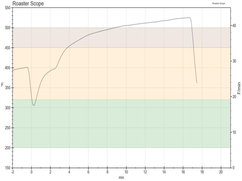
By adding a circuit to control the voltage going to the heater, and a thermocouple to measure the temperature of the air entering the roast chamber, it is possible to manually create very reproducible environmental conditions for roasting coffee beans. This profile was created by preheating the chamber to 392F as measured by the exhaust thermocouple with a power setting of 69%, E-stopping and charging, and rapidly increasing the power to 84% at 2.25 minutes into the roast. The exhaust temperature, not shown on the graph, slowly rises to 460F between 14-17 minutes, depending on the amount of beans being roasted. Over a period of several months, Renatoa provided answers to my many questions, for which I am very grateful. The heater control circuit is described here: http://coffeetime...mermod2017, with the simplification that the entire circuit consists of a DPDT switch and a $20 Chinese module that Renatoa showed me, https://www.amazo...NrPXRydWU=, takes input power and clips it to provide a desired percentage of the input power. Power is adjustable in 1% increments, and holding the button down slews the power at a rapid rate. The link also shows how to connect the input and output power leads. While unnecessary, being able to record the Input temperature is handy. I bought a Mastek MS6514 thermometer and connected it via USB to a laptop on which I run Artisan. The software allows me to use a previously captured roast and to display the environmental temperature in the background. if needed, I can make small changes in the heater power to follow the curve from the previous roast.
SkipG attached the following image:
Edited by SkipG on 09/16/2021 12:12 PM |
|
|
|
| SkipG |
Posted on 09/29/2021 10:23 AM
|
|
Newbie Posts: 11 Joined: April 16, 2021 |
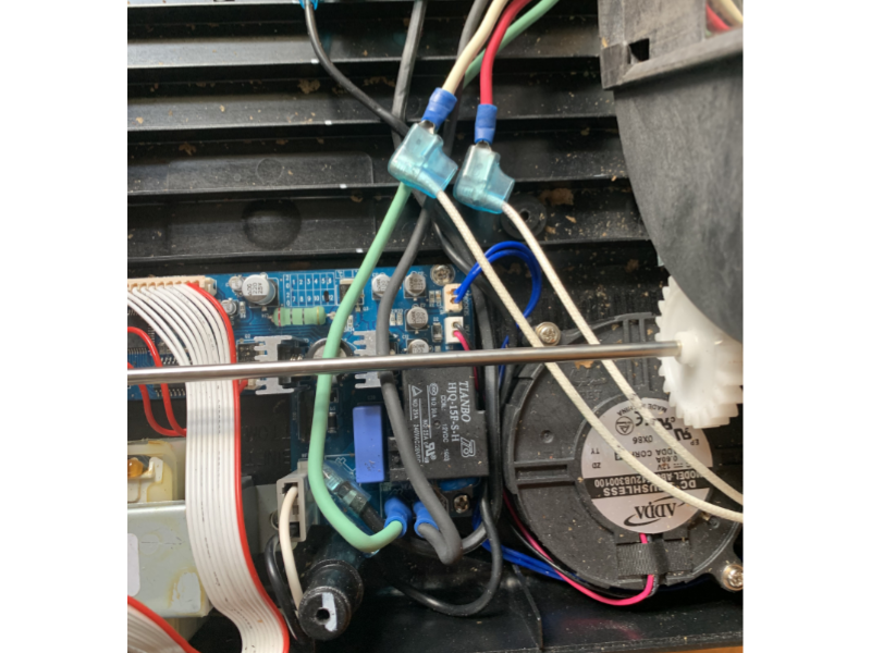
When I built the dimmer circuit the first time, I used 4x14AWG in a cable that was described as cable tray. The cable was quite stiff, and I wound up replacing it with 14 AWG "portable" cable which was much more flexible. When I first wired the "dimmer," there was no schematic on the website, but I read somewhere that the hot leads went on the two outer pins, and the two neutral wires went in the middle. I wired it that way, and it's been working fine. The diagram on the website shows the hot leads in the middle and the neutrals on the outside, so perhaps both work. Here is how I wired mine: The AC power for the heater is present at (male) pIns TRM3 and TRM4, and the two heater wires (female) connect there. Following the spirit of the 2017 dimmer mod, I added a 4 wire extension cable (6 feet of SJOOW, purchased at ShowMeCables.com), two wires for power in (connected to TRM3 (Black,F) and TRM4 (Green,F), and two wires for power to the heater. A red wire (Male) mated with the female previously connected to TRM3, and a white wire mated with the wire connected to TRM4. Wires Black -> TRM3 Red -> Heater Green -> TRM4 White -> Heater The other end of the cable goes to an ABS box containing a DPDT switch rated for 13 amps, which in one position returns the supplied power to the heater, while the other position returns the output off the dimm(er. I used a foot off the cable for the necessary jumper wires. I used ring connectors (crimp) for connecting wires to the switch. DPDT Switch Blk 1 4 Grn (Power In from GC, also power input to dimmer) Red 2 5 Wht (Power Out to heater) Red 3 6 Wht (Dimmer Power) Dimmer (aka, SCR) PWR in PWR out Blk Grn Wht Red Pictures showing pins 4,5,6 of DPDT switch and dimmer hookup in Control box, the cable passthrough and cable connections in the roaster:
SkipG attached the following images:


Edited by SkipG on 10/09/2021 6:58 AM Gene Cafe (modified), Kalita Pour Over setup.
|
|
|
|

| Jump to Forum: |
Powered by PHP-Fusion Copyright © 2024 PHP-Fusion Inc
Released as free software without warranties under GNU Affero GPL v3
Designed with ♥ by NetriXHosted by skpacman