Login
Shoutbox
You must login to post a message.
renatoa
07/26/2024 3:49 PM
Bill grubbe and Jk, 

allenb
07/26/2024 5:15 AM
Spiderkw Welcome to HRO!


renatoa
07/24/2024 8:31 AM
ramiroflores and John123,

 ?
?

 ?
?renatoa
07/21/2024 1:18 AM
 , Luislobo
renatoa
07/19/2024 11:28 AM
Koepea, 

Forum Threads
Newest Threads
Skywalker roaster modsBackground Roast Iss...
Hello from Arkansas
TC4ESP
Green coffee reviews
Hottest Threads
| Skywalker roaster... | [375] |
| TC4ESP | [115] |
| War on Farmers by... | [47] |
| Adventures in flu... | [26] |
| Hello! (soon) Roa... | [17] |
Donations
Latest Donations
dmccallum - 10.00
JackH - 25.00
snwcmpr - 10.00
Anonymous - 2.00
Anonymous - 5.00
dmccallum - 10.00
JackH - 25.00
snwcmpr - 10.00
Anonymous - 2.00
Anonymous - 5.00
Users Online
Guests Online: 4
Members Online: 0
Total Members: 8,393
Newest Member: Bill grubbe
Members Online: 0
Total Members: 8,393
Newest Member: Bill grubbe
View Thread
Who is here? 1 guest(s)
|
Rewire 230V popcorn machine fan & heater
|
|
| renatoa |
Posted on 10/20/2021 3:06 PM
|
|
Administrator  Posts: 3104 Joined: September 30, 2016 |
https://www.aliex...58593.html search string "4000w scr display" https://www.aliex...30644.html "PWM DC speed controller" https://www.aliex...29663.html "24V 3A power supply" Edited by renatoa on 10/20/2021 3:27 PM |
|
|
|
| renatoa |
Posted on 10/20/2021 3:28 PM
|
|
Administrator  Posts: 3104 Joined: September 30, 2016 |
Wrong url, double "https://", now it's ok. 24V 3A = 72W |
|
|
|
| Ploni |
Posted on 10/20/2021 4:05 PM
|
|
1/4 Pounder  Posts: 85 Joined: October 17, 2021 |
Do I need 3 components or 4? Is there anything else I need to order? Edited by Ploni on 10/21/2021 12:48 AM |
|
|
|
| renatoa |
Posted on 10/21/2021 2:16 AM
|
|
Administrator  Posts: 3104 Joined: September 30, 2016 |
There are three components: 1-2 power supply and speed controller for fan, and 3 power controller for heater. The list from post #12 has 4 lines because there are two choices of fan speed controller, with display and without. |
|
|
|
| Ploni |
Posted on 10/21/2021 5:33 AM
|
|
1/4 Pounder  Posts: 85 Joined: October 17, 2021 |
Yes, thank you. I reread that post and understood as much. I placed the order . . . might take a month. |
|
|
|
| Ploni |
Posted on 10/23/2021 7:01 PM
|
|
1/4 Pounder  Posts: 85 Joined: October 17, 2021 |
Hello, renatoa. Before the components arrive, is it a good idea to drill holes for ventilation in the plastic housing (like I've seen in many modification videos)? |
|
|
|
| renatoa |
Posted on 10/24/2021 3:19 AM
|
|
Administrator  Posts: 3104 Joined: September 30, 2016 |
there didn't seem to be a need for modified poppers so far |
|
|
|
| Ploni |
Posted on 10/24/2021 4:49 AM
|
|
1/4 Pounder  Posts: 85 Joined: October 17, 2021 |
OK. Thanks. |
|
|
|
| Ploni1 |
Posted on 11/11/2021 5:03 AM
|
|
Newbie  Posts: 1 Joined: November 10, 2021 |
power reg component has arrived
Ploni1 attached the following image:
|
|
|
|
| Ploni |
Posted on 11/14/2021 4:01 PM
|
|
1/4 Pounder  Posts: 85 Joined: October 17, 2021 |
Yes. Thank you. Question: What is the maximum quantity of beans that can be roasted in this modified machine in one roasting session? I would like to be able to roast once a week just enough beans for six (6) 16-ounce cups per week . . . that is, I think, approximately 120 grams of ground beans. |
|
|
|
| renatoa |
Posted on 11/15/2021 1:20 AM
|
|
Administrator  Posts: 3104 Joined: September 30, 2016 |
This equates to approximately 150 grams of greens. Two roasts of 75 grams are ok for a 60 grams rated machines, even if motor is left to standard 19V power. A forced motor, over-volted at 24V, can lift even 120 grams, but shorter life. So the only care is to avoid the very low capacity machines, rated for 30 grams. Some have this rating printed on the box, some in fine prints, some nowhere. For the the last best guess is the size of the popcorn feeding cup. Edited by renatoa on 11/15/2021 8:09 AM |
|
|
|
| Ploni |
Posted on 11/15/2021 6:44 AM
|
|
1/4 Pounder  Posts: 85 Joined: October 17, 2021 |
So the machine we're looking to build/modify can roast up to 75 grams at a time? The other two components arrived today.
Ploni attached the following image:
|
|
|
|
| renatoa |
Posted on 11/15/2021 8:08 AM
|
|
Administrator  Posts: 3104 Joined: September 30, 2016 |
Even more, depends how much you want to push the voltage. 75 is just the number computed based on your requirements. To me the issue wasn't lifting over 100 grams, but not overspill when beans are in the finish stage, if no extension is done to the roast chamber. |
|
|
|
| Ploni |
Posted on 11/15/2021 12:25 PM
|
|
1/4 Pounder  Posts: 85 Joined: October 17, 2021 |
Hi, renatoa. You wrote on 10/18: <<First step, disconnect plugs 1-2 from the thermostat,>> DONE <<and use those terminals for heater control, ssr or a variator>> I'M GOING TO NEED FURTHER INSTRUCTIONS ON THIS. DO I REMOVE THE PLUG-CLIPS FROM THIS BLUE & THIS WHITE WIRE? <<Second, . . . For this task unsolder/cut the red wire from pad 3 and insulate it, no more useful, is the motor voltage tap.>> DONE <<Then unsolder/cut the white wires from pad 4 and connect them together, preferably crimping not soldering. Insulate the join of white wires.>> QUESTION: AFTER I UNSOLDER THE WHITE WIRES FROM THE BOARD (THE ONE WITH THE TERMINAL THAT WAS PREVIOUSLY CONNECTED TO THE THERMOSTAT & THE ONE LEADING IN TO THE HEATING ELEMENT), I SHOULD THEN CRIMP THEM TOGETHER . . . THAT IS, CRIMP THEIR ENDS TOGETHER THAT WERE PREVIOUSLY EACH SOLDERED TO THE BOARD? <<Use the free PCB pads to power the motor from external source.>> I'LL NEED FURTHER EXPLANATION HERE ALSO. THANKS! |
|
|
|
| renatoa |
Posted on 11/15/2021 1:18 PM
|
|
Administrator  Posts: 3104 Joined: September 30, 2016 |
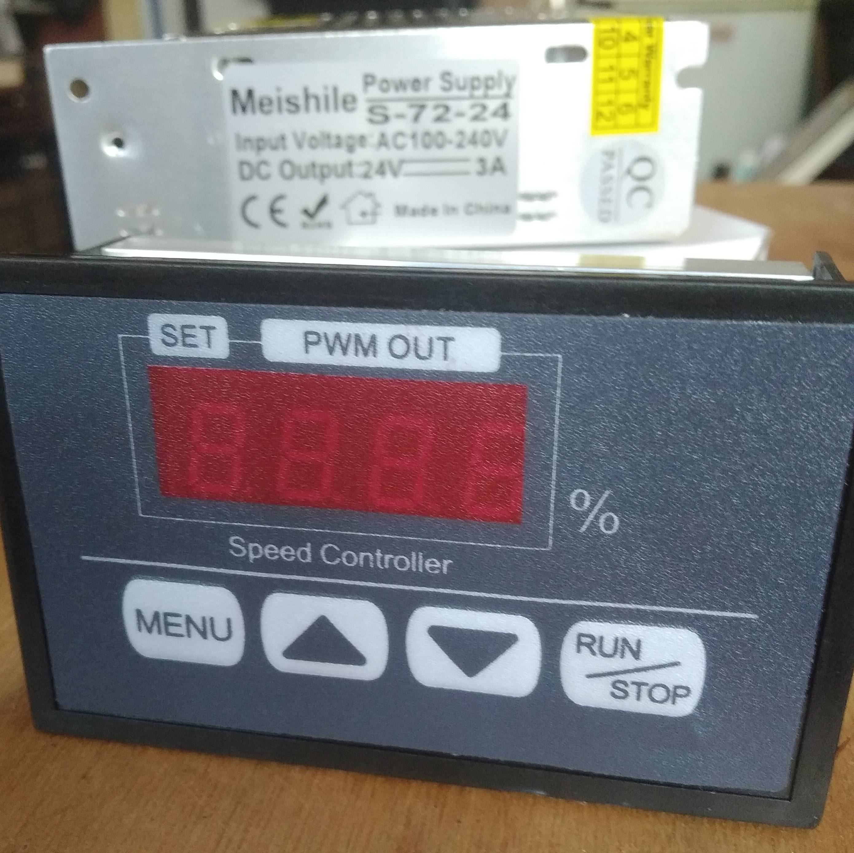
Will start with the last item in the list, the power to fan motor, because a fluid bed needs airflow before heat, this is mandatory ! The PWM controller shown above has a lateral terminal block with four screws, the green plastic. May we have a picture of the labels on this terminal block ? There is nothing visible in the aliexpress pics. |
|
|
|
| Ploni |
Posted on 11/16/2021 1:13 PM
|
|
1/4 Pounder  Posts: 85 Joined: October 17, 2021 |
The PWM controller
Ploni attached the following image:
Edited by Ploni on 11/16/2021 1:29 PM |
|
|
|
| Ploni |
Posted on 11/16/2021 4:08 PM
|
|
1/4 Pounder  Posts: 85 Joined: October 17, 2021 |
24V power
Ploni attached the following image:
|
|
|
|
| renatoa |
Posted on 11/17/2021 12:47 AM
|
|
Administrator  Posts: 3104 Joined: September 30, 2016 |
Great ! L/N of power box goes to a mains cable. If grounding wire available in the mains cable, connect to the middle terminal, with the ground symbol. V+V- goes to speed controller Power+/- Beware to not reverse polarity ! Power the 24V source, and you should see activity on speed controller screen. Edited by renatoa on 11/17/2021 2:12 AM |
|
|
|
| Ploni |
Posted on 11/17/2021 1:23 AM
|
|
1/4 Pounder  Posts: 85 Joined: October 17, 2021 |
Thanks. This is exciting. What type & specs do I need for the wires to connect these components? What lengths? (I forgot to say "Good morning!") Edited by Ploni on 11/17/2021 1:32 AM |
|
|
|
| renatoa |
Posted on 11/17/2021 2:13 AM
|
|
Administrator  Posts: 3104 Joined: September 30, 2016 |
All cables length, as short as you plan to arrange them in an enclosure. The wire size, similar as the wires of the popper. I have stock of AWG18, rated for 16 amps, and use it for all my projects, where currents bigger than 2 Amps are involved. In a 230V popper the motor draws 2--3 Amps, and the heater 6-8 Amps. For electronics, low voltage and currents, you can buy network (LAN) cable and extract the individual 24-26AWG wires, there are 8 different color wires inside. |
|
|
|
| Ploni |
Posted on 11/17/2021 11:55 AM
|
|
1/4 Pounder  Posts: 85 Joined: October 17, 2021 |
Correct? If so, what's next?
Ploni attached the following image:
|
|
|
|
| renatoa |
Posted on 11/17/2021 12:18 PM
|
|
Administrator  Posts: 3104 Joined: September 30, 2016 |
Using wires extracted from a mains cable could led to confusions, or even worse. Please let those colors reserved only for 230VAC mains wiring. Use red for + of any DC circuit and black for minus. |
|
|
|
| Ploni |
Posted on 11/17/2021 1:39 PM
|
|
1/4 Pounder  Posts: 85 Joined: October 17, 2021 |
As I mentioned last month, I have some but very little experience in electronics. Please specify what to do in detail and I'll do it. Is the green-yellow wire correct in all aspects except it should be replaced with a red wire? Is the blue wire connection correct except it should be replaced with a black wire? Edited by Ploni on 11/17/2021 2:22 PM |
|
|
|
| Ploni |
Posted on 11/18/2021 12:23 PM
|
|
1/4 Pounder  Posts: 85 Joined: October 17, 2021 |
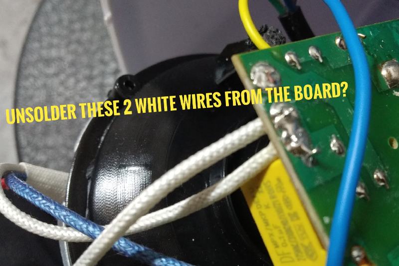
I have fixed the wire color problem. Can we continue? Unsolder these two (2) white wires, crimp them together, and insulate the connection?
Ploni attached the following image:
Edited by Ploni on 11/18/2021 1:44 PM |
|
|
|
| renatoa |
Posted on 11/18/2021 1:47 PM
|
|
Administrator  Posts: 3104 Joined: September 30, 2016 |
Yes, is mandatory, in order to have the motor disconnected from heater circuitry. |
|
|
|
| Jump to Forum: |
Powered by PHP-Fusion Copyright © 2024 PHP-Fusion Inc
Released as free software without warranties under GNU Affero GPL v3
Designed with ♥ by NetriXHosted by skpacman


