
Login

Shoutbox
You must login to post a message.
renatoa
07/26/2024 3:49 PM
Bill grubbe and Jk, 
allenb
07/26/2024 5:15 AM
Spiderkw Welcome to HRO!

renatoa
07/24/2024 8:31 AM
ramiroflores and John123,

 ?
?
?renatoa
07/21/2024 1:18 AM
 , Luislobo
renatoa
07/19/2024 11:28 AM
Koepea,
Forum Threads
Newest Threads
Skywalker roaster modsBackground Roast Iss...
Hello from Arkansas
TC4ESP
Green coffee reviews
Hottest Threads
| Skywalker roaster... | [375] |
| TC4ESP | [115] |
| War on Farmers by... | [47] |
| Adventures in flu... | [26] |
| Hello! (soon) Roa... | [17] |
In Memory Of Ginny

Donations
Latest Donations
dmccallum - 10.00
JackH - 25.00
snwcmpr - 10.00
Anonymous - 2.00
Anonymous - 5.00
dmccallum - 10.00
JackH - 25.00
snwcmpr - 10.00
Anonymous - 2.00
Anonymous - 5.00
Users Online
Guests Online: 7
Members Online: 0
Total Members: 8,394
Newest Member: Bill grubbe
Members Online: 0
Total Members: 8,394
Newest Member: Bill grubbe
View Thread
Who is here? 1 guest(s)
Page 1 of 2: 12
|
 Starting a TO build
|
|
| zamunda |
Posted on 05/20/2022 10:09 AM
|
 1/4 Pounder  Posts: 173 Joined: November 17, 2020 |
Quote zamunda wrote: OK, so I connect the TO directly to the power-variator and set/let the thermostat of the TO at max, that is 225C? That is what I did and loaded 350 grams at 80% heat (did not follow the profile exactly yet) but I am happy with the result that came out! ########################
### A lot can happen over coffee ### ######################## |
|
|
|
| renatoa |
Posted on 05/20/2022 10:09 AM
|
|
Administrator Posts: 3104 Joined: September 30, 2016 |
Mmmm... not so simple  The motor is preferably to not pass through power variator, the a/c sine wave chopping done by the variator is not pleasing for all motor types. The variator output should go to the lamp only, and thermostat bypassed. What solution used for chaff/smoke exhaust ? |
|
|
|
| zamunda |
Posted on 05/20/2022 10:23 AM
|
|
1/4 Pounder Posts: 173 Joined: November 17, 2020 |
Quote renatoa wrote: Mmmm... not so simple The motor is preferably to not pass through power variator, the a/c sine wave chopping done by the variator is not pleasing for all motor types. The variator output should go to the lamp only, and thermostat bypassed. OK, I understand. Quote What solution used for chaff/smoke exhaust ? Not yet... ########################
### A lot can happen over coffee ### ######################## |
|
|
|
| Koffee Kosmo |
Posted on 05/20/2022 5:33 PM
|
 Administrator Posts: 1621 Joined: December 31, 2008 |
The agitation looks much better Test with a few coloured beans to see how they travel through the bean mass I have spent countless hours fine tuning the agitator to have a complete mixing action rather than to push a mass of coffee beans around the roasting bowl The main purpose of the agitator shape is to mix the beans in a specific way that is to move the beans from the centre out and back to the centre again The action also cycles the beans from top to bottom in a helix pattern while also allowing the beans some intermittent rest time. As for the heat shield I have not removed it completely on my unit Best of both worlds is to cut out 90% and still retain an outer ring https://i.postimg...-C91-A.jpg KK I home roast and I like it. Designer of the KKTO
Roaster Build information https://homeroast...ad_id=1142 https://docs.goog...lide=id.i0 Blog - http://koffeekosm...gspot.com/ Bezzera Strega, Mazzer Robur Grinder, Pullman Tamper Convex, (KKTO) Turbo Oven Home Roaster. |
|
|
|
| renatoa |
Posted on 05/21/2022 1:20 AM
|
|
Administrator Posts: 3104 Joined: September 30, 2016 |
At least a cut in the middle, having the size of turbine circle, will avoid chaff to clogg and burn on the the lamp shield. This is the most recommended step to do after the first roasting attempts enthusiasm gone. |
|
|
|
| zamunda |
Posted on 05/21/2022 5:33 AM
|
|
1/4 Pounder Posts: 173 Joined: November 17, 2020 |
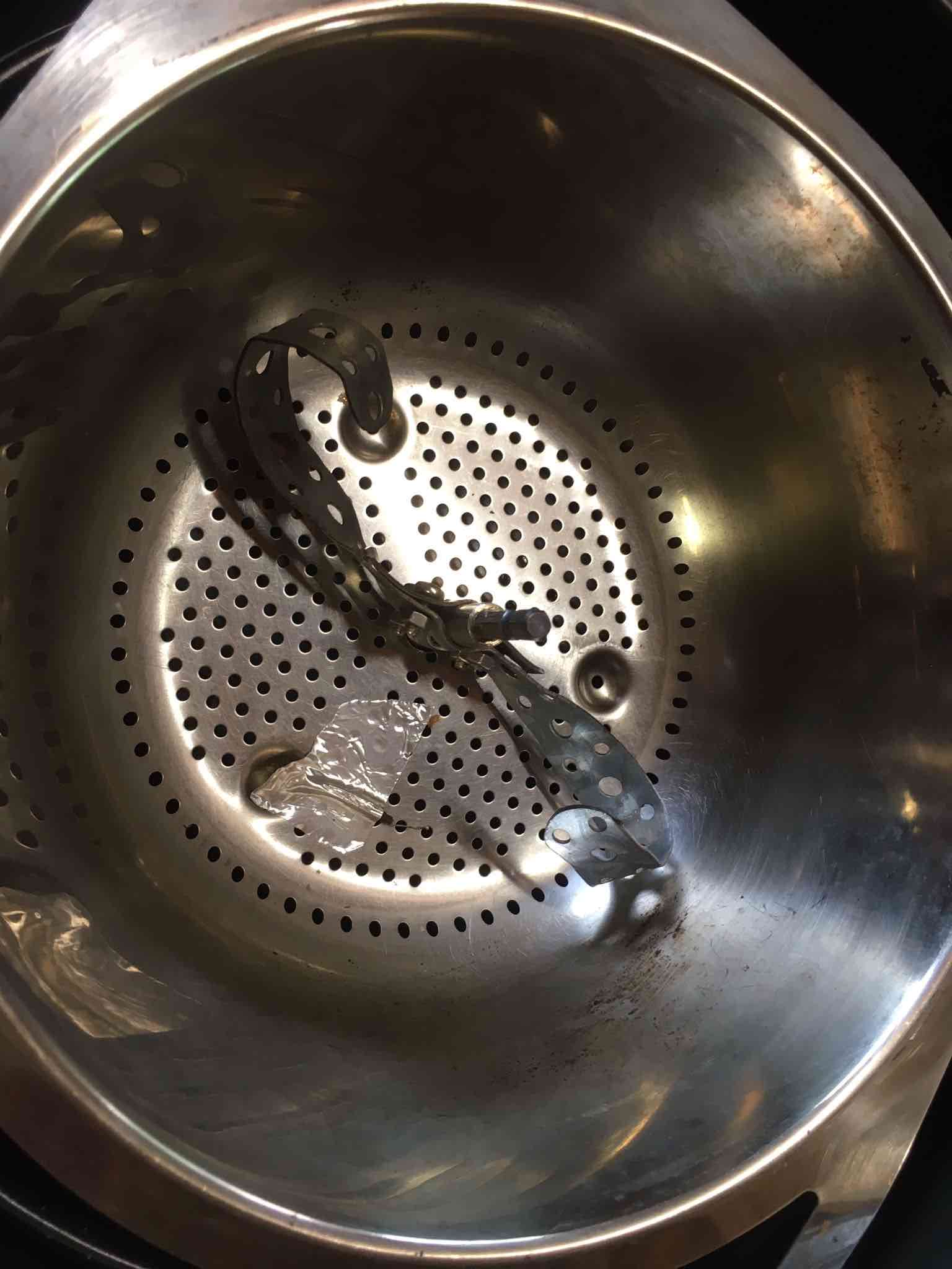
Quote Koffee Kosmo wrote: The agitation looks much better Test with a few coloured beans to see how they travel through the bean mass I have spent countless hours fine tuning the agitator to have a complete mixing action rather than to push a mass of coffee beans around the roasting bowl The main purpose of the agitator shape is to mix the beans in a specific way that is to move the beans from the centre out and back to the centre again The action also cycles the beans from top to bottom in a helix pattern while also allowing the beans some intermittent rest time. Thanks for this info, I'll do that! Quote As for the heat shield I have not removed it completely on my unit Best of both worlds is to cut out 90% and still retain an outer ring https://i.postimg...-C91-A.jpg I removed the inner part as indicated (see below). Question: why does your lamp look transparant with a spriral inside while mine looks solid? I thought mine was just covered with dirt/oil etc but I am not sure, could not get it off.
zamunda attached the following images:


########################
### A lot can happen over coffee ### ######################## |
|
|
|
| zamunda |
Posted on 05/21/2022 5:39 AM
|
|
1/4 Pounder Posts: 173 Joined: November 17, 2020 |
Quote renatoa wrote: Mmmm... not so simple The motor is preferably to not pass through power variator, the a/c sine wave chopping done by the variator is not pleasing for all motor types. The variator output should go to the lamp only, and thermostat bypassed. Are there pics/vids/threat of this specific mod? Couldn't find them so far... Edited by zamunda on 05/21/2022 6:47 AM ########################
### A lot can happen over coffee ### ######################## |
|
|
|
| zamunda |
Posted on 05/21/2022 5:41 AM
|
|
1/4 Pounder Posts: 173 Joined: November 17, 2020 |
Quote renatoa wrote: At least a cut in the middle, having the size of turbine circle, will avoid chaff to clogg and burn on the the lamp shield. This is the most recommended step to do after the first roasting attempts enthusiasm gone. OK, thanks, I removed the middle part. Question: where should the thermocouple go? Is this a good place?
zamunda attached the following images:
########################
### A lot can happen over coffee ### ######################## |
|
|
|
| renatoa |
Posted on 05/21/2022 6:13 AM
|
|
Administrator Posts: 3104 Joined: September 30, 2016 |
Yes, looks good, and even better would be to insulate the sensor from the pan, using a termo-resistant plastic, as kapton tape, or silicone pad. The goal is to minimize influence of pan thermal inertia, to measure as much beans as possible. Commercial surface probes are done as a kapton-junction-metal sandwich, as you can see here: https://perfectpr...cts/tl0225 ~~~
renatoa attached the following image:

|
|
|
|
| zamunda |
Posted on 05/22/2022 3:46 AM
|
|
1/4 Pounder Posts: 173 Joined: November 17, 2020 |
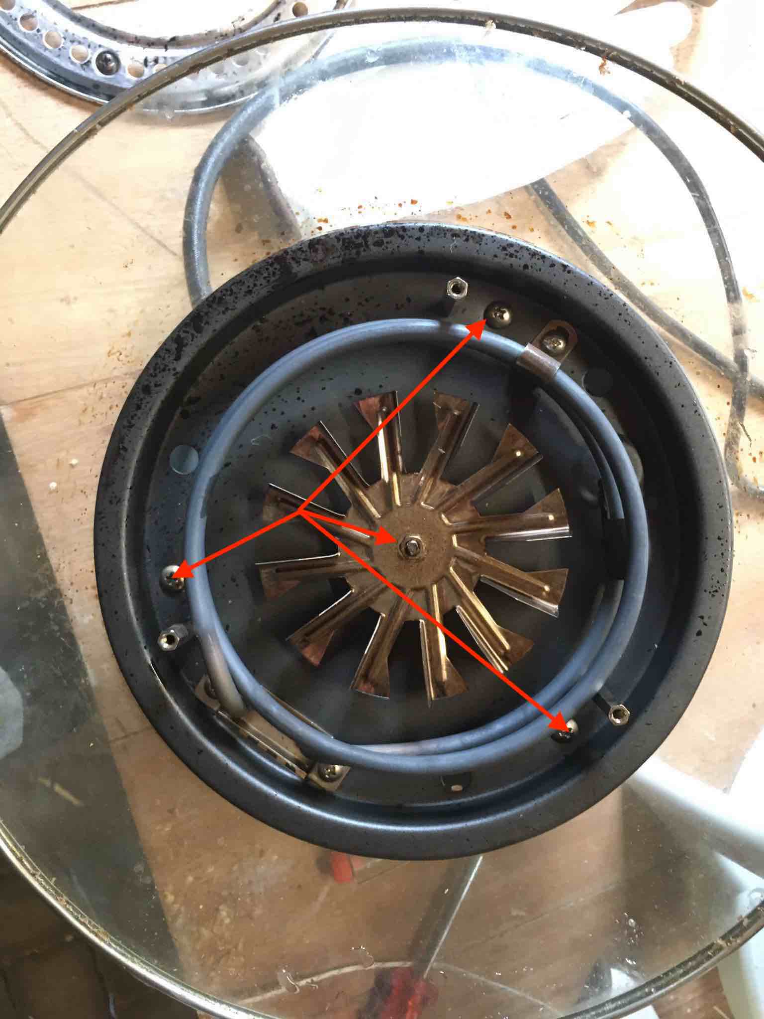
Quote zamunda wrote: Quote renatoa wrote: Mmmm... not so simple The motor is preferably to not pass through power variator, the a/c sine wave chopping done by the variator is not pleasing for all motor types. The variator output should go to the lamp only, and thermostat bypassed. Are there pics/vids/threat of this specific mod? Couldn't find them so far... Since I would like to separate AC for the fan and the lamp, I attempted to open it, I guess I should removing these 4 screws at least but done that, still can get it out. Which ones do I miss?
zamunda attached the following image:
########################
### A lot can happen over coffee ### ######################## |
|
|
|
| renatoa |
Posted on 05/22/2022 5:47 AM
|
|
Administrator Posts: 3104 Joined: September 30, 2016 |
The hex raisers of the lamp shield are those keeping everything in one piece, in the models I know. Check here, at 0:48 |
|
|
|
| zamunda |
Posted on 05/22/2022 6:06 AM
|
|
1/4 Pounder Posts: 173 Joined: November 17, 2020 |
Thanks!!!
########################
### A lot can happen over coffee ### ######################## |
|
|
|
| zamunda |
Posted on 05/22/2022 7:46 AM
|
|
1/4 Pounder Posts: 173 Joined: November 17, 2020 |
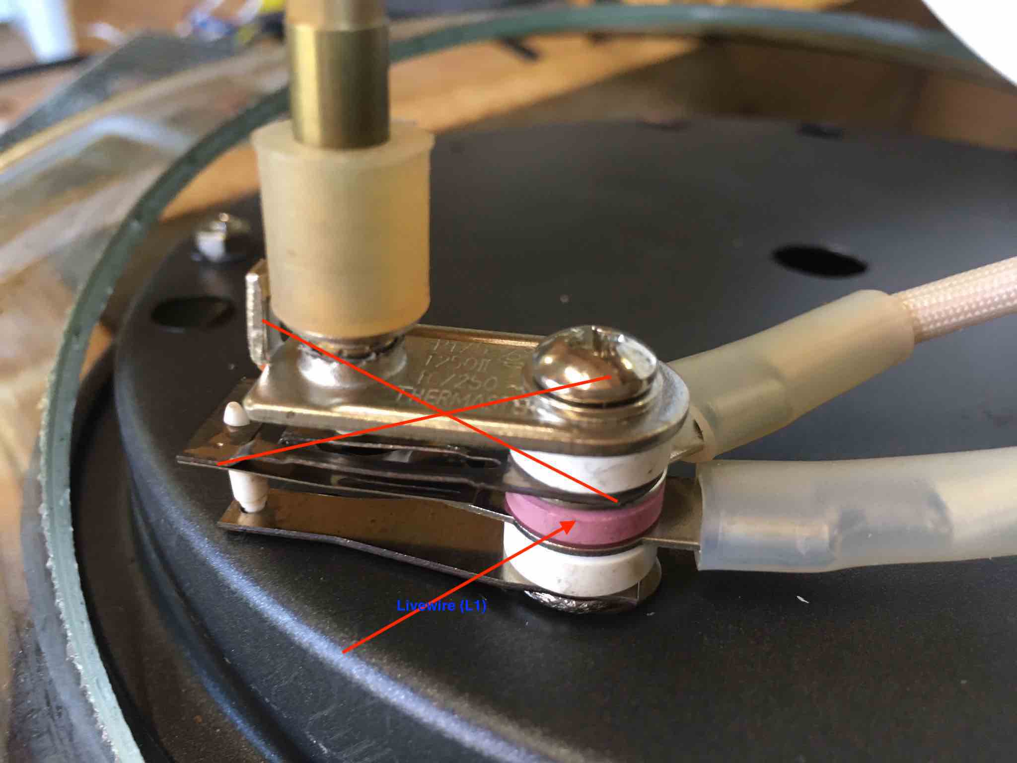
Quote renatoa wrote: The hex raisers of the lamp shield are those keeping everything in one piece, in the models I know. Check here, at 0:48 In my case, the hex raisers turned out to be only the placeholders for the lamp shield, nothing more. What I had missed was the screw at the top of the knot for temp regulation (image 1). After removing that one as well I could remove the knot and seperate the different parts. Now for separating AC of the lamp, I "think" I should proceed as follows: 1. Remove the bi-metal thermostat and connect the hotwire for the lamp there (L1), image 2 2. Connect ground and neutral as indicated in image 3. Is this correct? Thanks
zamunda attached the following images:


Edited by zamunda on 05/22/2022 7:51 AM ########################
### A lot can happen over coffee ### ######################## |
|
|
|
| zamunda |
Posted on 05/22/2022 8:36 AM
|
|
1/4 Pounder Posts: 173 Joined: November 17, 2020 |
Finally I connected it like this (see image), not tested yet. This way the light indicator reminds me if the heating is on/off For now, I am thinking of not removing the bi-metal for safety and leaving the control at 225C (=max). Would that have any drawbacks? If you see any flaws, please let me know. Regards
zamunda attached the following image:

########################
### A lot can happen over coffee ### ######################## |
|
|
|
| zamunda |
Posted on 05/22/2022 12:03 PM
|
|
1/4 Pounder Posts: 173 Joined: November 17, 2020 |
Hello, I proceeded as explained above, put everything together and tested: 1. First tested fan: green control led was lighting up and fan worked well as before. 2. Then tested heat: put temp control to 225C (Max), turned on heat, orange control led was lighting up but no heat! What could have been gone wrong? Could the bulb have been damaged by disassembling/assembling? Any other ideas? Thanks!
zamunda attached the following image:

########################
### A lot can happen over coffee ### ######################## |
|
|
|
| renatoa |
Posted on 05/23/2022 6:54 AM
|
|
Administrator Posts: 3104 Joined: September 30, 2016 |
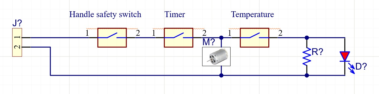
Attached is the typical electrical schematic of a TO lid, as sketchy as I can do it in a hurry. Left side is the mains cable+plug, 1 being the live/switched line, 2 being the neutral/common line. First switch is in the handle, for safety, whenever you need quickly to cut everything, simply raise up the handle. Then follows the timer, that powers permanently the motor, when is ticking. Then follows the thermostat, that powers the heater and red lamp. Green lamp is not drawn, should be connected after or before the handle safety switch. All black dots in schematic are three or more wire connections, done inside those white drops in your picture. My guess is when you dismantled the thermostat-red_lamp-heater connection, you left the heater unconnected, somewhat. ~~~
renatoa attached the following image:
|
|
|
|
| zamunda |
Posted on 05/23/2022 9:02 AM
|
|
1/4 Pounder Posts: 173 Joined: November 17, 2020 |
Quote renatoa wrote: Attached is the typical electrical schematic of a TO lid, as sketchy as I can do it in a hurry. Left side is the mains cable+plug, 1 being the live/switched line, 2 being the neutral/common line. First switch is in the handle, for safety, whenever you need quickly to cut everything, simply raise up the handle. Then follows the timer, that powers permanently the motor, when is ticking. Then follows the thermostat, that powers the heater and red lamp. Green lamp is not drawn, should be connected after or before the handle safety switch. All black dots in schematic are three or more wire connections, done inside those white drops in your picture. My guess is when you dismantled the thermostat-red_lamp-heater connection, you left the heater unconnected, somewhat. ~~~ Hello Renatoa, Thanks for this! You were right, when adding an extra cable to seperate heater and fan, I had seperated the live wire of the heating and connected that to L1 of the new cable. Then I connected the neutral of the lamp to the (0) of the new cable. That gave me a closed circuit and the lamp worked as indicated. However, what I missed was to connect the neutral wire of the heater also to the 0 of the new cable since lamp and heater are connected in "parallel" (if I recall well from secondary school?). When connecting like this everything works as expected, I can control fan and heating seperately and control the power of the heating by using the power variator! ########################
### A lot can happen over coffee ### ######################## |
|
|
|
| zamunda |
Posted on 05/23/2022 9:43 AM
|
|
1/4 Pounder Posts: 173 Joined: November 17, 2020 |
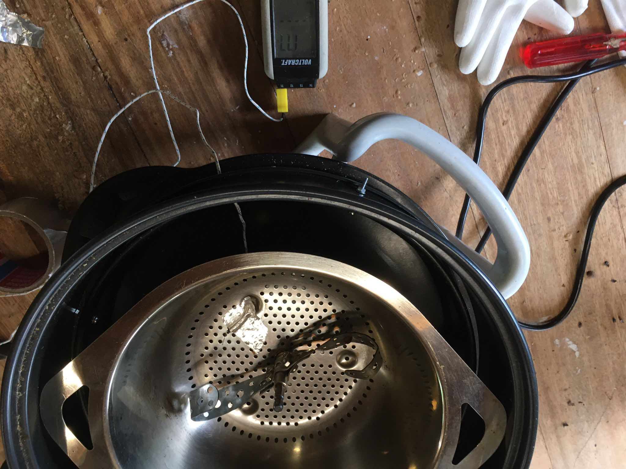
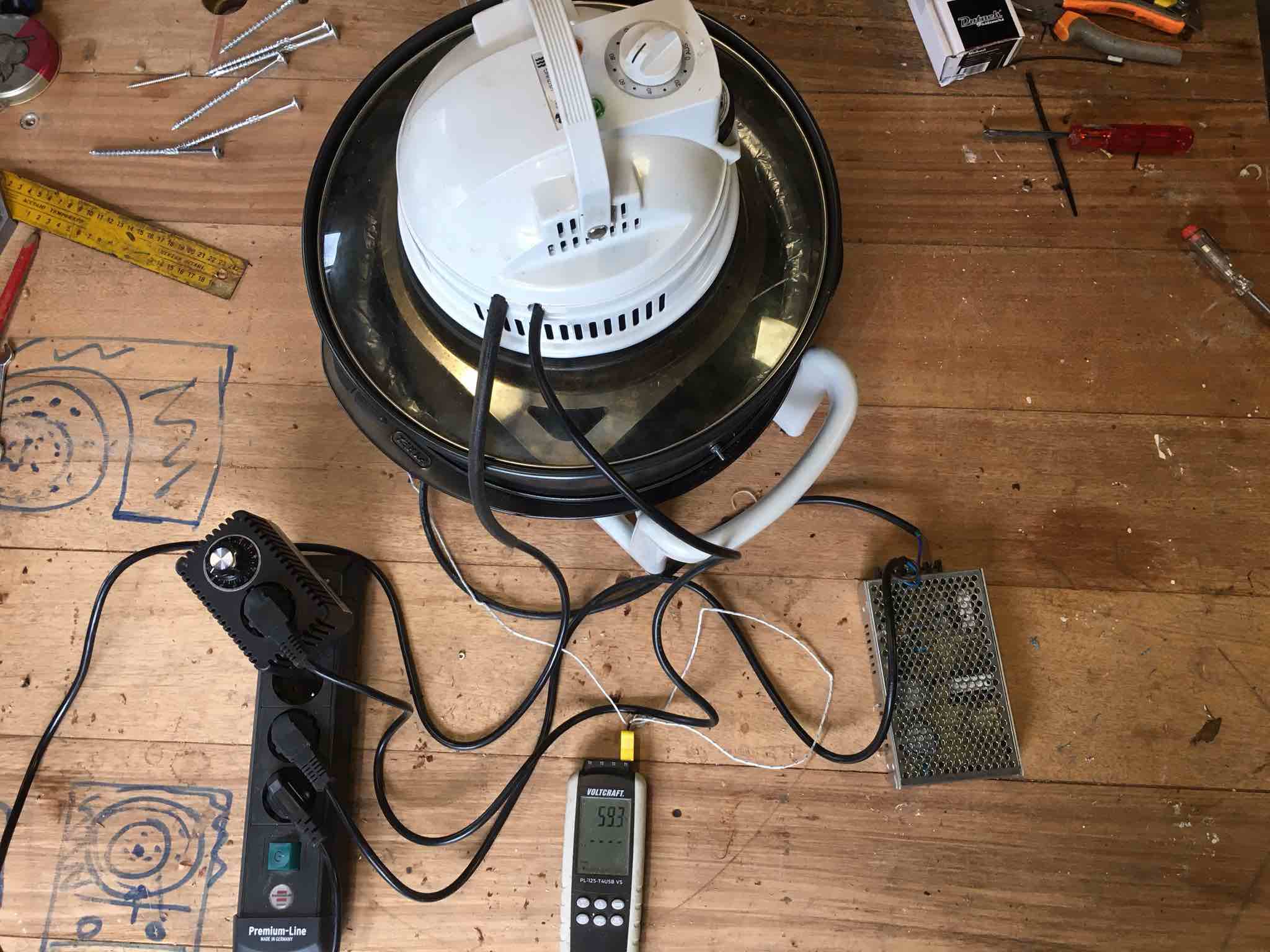
This is how my working set-up looks now. 1 cable goes to the motor for agitating the beans, 1 cable to the fan , 1 cable for the heater (which can be controlled with a powervariator)...
zamunda attached the following image:
########################
### A lot can happen over coffee ### ######################## |
|
|
|
| zamunda |
Posted on 05/23/2022 12:09 PM
|
|
1/4 Pounder Posts: 173 Joined: November 17, 2020 |
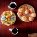
And this is a nice result I think: 500 Grs washed coffee from Colombia. Did a preheat until 200C, charged, power at 75%, left it there, FC arrived at 11 mts 55. Drop at 12.40.
zamunda attached the following image:

Edited by zamunda on 05/23/2022 2:08 PM ########################
### A lot can happen over coffee ### ######################## |
|
|
|

Page 1 of 2: 12
| Jump to Forum: |
Powered by PHP-Fusion Copyright © 2024 PHP-Fusion Inc
Released as free software without warranties under GNU Affero GPL v3
Designed with ♥ by NetriXHosted by skpacman