
Login

Shoutbox
You must login to post a message.
renatoa
07/26/2024 3:49 PM
Bill grubbe and Jk, 
allenb
07/26/2024 5:15 AM
Spiderkw Welcome to HRO!

renatoa
07/24/2024 8:31 AM
ramiroflores and John123,

 ?
?
?renatoa
07/21/2024 1:18 AM
 , Luislobo
renatoa
07/19/2024 11:28 AM
Koepea,
Forum Threads
Newest Threads
Skywalker roaster modsBackground Roast Iss...
Hello from Arkansas
TC4ESP
Green coffee reviews
Hottest Threads
| Skywalker roaster... | [375] |
| TC4ESP | [115] |
| War on Farmers by... | [47] |
| Adventures in flu... | [26] |
| Hello! (soon) Roa... | [17] |
In Memory Of Ginny

Donations
Latest Donations
dmccallum - 10.00
JackH - 25.00
snwcmpr - 10.00
Anonymous - 2.00
Anonymous - 5.00
dmccallum - 10.00
JackH - 25.00
snwcmpr - 10.00
Anonymous - 2.00
Anonymous - 5.00
Users Online
Guests Online: 6
Members Online: 0
Total Members: 8,393
Newest Member: Bill grubbe
Members Online: 0
Total Members: 8,393
Newest Member: Bill grubbe
View Thread
Who is here? 1 guest(s)
 SR800/SR540 Fan Current TC4+
|
|
| Gullygossner |
Posted on 10/19/2022 8:58 PM
|
|
1/4 Pounder  Posts: 95 Joined: January 06, 2019 |
Just wondering if anyone has powered their SR800/SR540 fan with a seperate DC power supply? I am trying to find a suitable power supply to indipendently power the fan. I found this post (https://homeroasters.org/forum/viewthread.php?thread_id=6556) which suggests some therotical current values between 3-6A. I am thinking that the 3-4A range is probably correct (maybe wishful thinking, as it would make this mod much simpler) but am curious if anyone else has real world experience. My Plan (maybe wishful) is to use the TC4+ for fan control (if the current of the fan motor is below 4A) and use a Robotdyn AC dimmer for the heater controls. I am mildly hesitent using the Robotdyn AC dimmer for the heaters but I have come across a few examples of members using them for heater control. I am not opposed to using an SSR if it is better suited for the job but I happen to have a Robotdyn AC dimmer that isn't in use so it would be my preference. |
|
|
|
| renatoa |
Posted on 10/20/2022 5:10 AM
|
|
Administrator Posts: 3104 Joined: September 30, 2016 |
What voltage is that motor ? Mains 110V or smaller? What you mean by independently ? Work alone without heater. If the fan speed is variable, then IT IS independent, is not using a tap circuitry, as European popper models, where the fan motor can't be spin without heater active. Regarding the dimmer, as the name suggest, an AC dimmer can be used for an AC circuit control, not suitable for DC control. DC loads duty cycle are controlled using a PWM driver. |
|
|
|
| Gullygossner |
Posted on 10/20/2022 6:22 AM
|
|
1/4 Pounder Posts: 95 Joined: January 06, 2019 |
Quote renatoa wrote: What voltage is that motor ? Mains 110V or smaller? What you mean by independently ? Work alone without heater. If the fan speed is variable, then IT IS independent, is not using a tap circuitry, as European popper models, where the fan motor can't be spin without heater active. Regarding the dimmer, as the name suggest, an AC dimmer can be used for an AC circuit control, not suitable for DC control. DC loads duty cycle are controlled using a PWM driver. Apologies, I may have worded my post poorly. The Fan motor is a DC motor powered via a bridge rectifier from mains power similar to a popper. From what I know it is a 30V DC motor but there is no other ratings. The unit does have idenpendent control currently but I want to use the TC4+ for greater control. The TC4+ would be used for pwm control on the fan and the AC dimmer would be used for the heater coils. |
|
|
|
| renatoa |
Posted on 10/20/2022 8:32 AM
|
|
Administrator Posts: 3104 Joined: September 30, 2016 |
Interesting to find this... wondering how looks the 30V source, probably about 100W, hosted inside those apparently tiny SR's. For TC4 DC fan control, the typical solution is to use PWM: a MOSFET driver fed by IO3 output/command. For original TC4 boards the MOSFET driver is purchased separately, as a board similar to RobotDyn dimmer. Because TC4+ already has embedded this driver, your task is even easier. One notice though... the creator of TC4+ rate his embedded DC driver up to 24V only, even if the datasheet of the MOSFET switcher used shows it is capable up to 100V... so should work for your 30V... Probably is better to ask in the TC4+ thread why this limitation. A similar thread here: https://homeroast...ad_id=6546 Edited by renatoa on 10/20/2022 8:42 AM |
|
|
|
| Gullygossner |
Posted on 10/20/2022 10:01 AM
|
|
1/4 Pounder Posts: 95 Joined: January 06, 2019 |
It looks like the fan draws about 250W based on meter readings without the heater on. TC4+ wouldn't be up to the task for that current anyhow so maybe a DCDC SSR or one of these (https://www.cytro...tor-driver) motor drivers would be required.
Edited by renatoa on 10/20/2022 1:13 PM |
|
|
|
| renatoa |
Posted on 10/20/2022 1:16 PM
|
|
Administrator Posts: 3104 Joined: September 30, 2016 |
guesstimated the power based on your current assumptions: 30V * 4A = 120W The TC4+ driver needs a heatsink smaller than a matchbox to cope with 4A. 250W power source is to big to fit in a SR... is about half of a PC ATX brick. |
|
|
|
| Gullygossner |
Posted on 10/20/2022 1:49 PM
|
|
1/4 Pounder Posts: 95 Joined: January 06, 2019 |
Quote renatoa wrote: guesstimated the power based on your current assumptions: 30V * 4A = 120W The TC4+ driver needs a heatsink smaller than a matchbox to cope with 4A. 250W power source is to big to fit in a SR... is about half of a PC ATX brick. The guestimated power draw was based on assumptions I found in a previous post linked in the first post. The actual power readings show 8.3A power draw so an external dc power source would be required because as you mentioned, it would be big. I am taking the power draw from somebody else so I will test it myself to confirm. you also mentioned the 24V cap on the TC4+ so 30V will not work unless I were to swap that out. Overall it looks doable I'll just need a few pieces of additional hardware. |
|
|
|
| renatoa |
Posted on 10/20/2022 3:11 PM
|
|
Administrator Posts: 3104 Joined: September 30, 2016 |
Sorry, maybe I wasn't clear enough... Did you opened you SR roaster ? Please can you show me the actual power source of the fan motor ? Because I highly doubt the power levels we are debating here. The pictures from the post linked in the first post shows a ridiculous tiny motor that can't be rated for that power by any criteria. The first and most important reason is that you don't need that power... I did tests with 100W pumps used for inflatable pools that lift 250 grams with no issue. For the 140 grams load of SR540 you don't need more than 50-70 watts of pure power. So yes, it's doable, but don't over-engineer it...  I would give a try of TC4+ driver without any hesitation or fear. You don't risk to break the board, but the mosfet alone. Edited by renatoa on 10/20/2022 3:22 PM |
|
|
|
| Gullygossner |
Posted on 10/20/2022 10:59 PM
|
|
1/4 Pounder Posts: 95 Joined: January 06, 2019 |
Just to be clear this is the sr800 so the bean loads are a little higher. Currently t the bottle neck is the chamber size, limiting the roast to about 230g. I start my roasts out with the fan at 8 (the fan scale is 9-1) and after a minute of drying can turn that down to 7/6 depending on ambient temperature. I've got a larger roast chamber in the mail so i would like the headroom for larger charge size. I did my own power testing tonight and with the unit in cooling mode and the fan set to full power I saw 236W. That does lead me to a question. This roaster is similar to popcorn popper in that it uses a bridge rectifier to drop 120v Ac voltage to 30v DC voltage. Would the small resistance coil (I think it's 100ohm, but haven't measured) that is used for the voltage drop to the bridge rectifier contribute to the 230w when the unit is in cooling mode? The smaller resistance coil would be dropping the voltage 90v so would it be a straight portion where 120v=230w (resistance coil and motor power) so the resistance coil is displaying 172.5W making the current to the motor ~2A? That would make the motor power only 60W which seams low. |
|
|
|
| dwertz |
Posted on 10/20/2022 11:31 PM
|
|
Newbie  Posts: 45 Joined: October 19, 2022 |
Is there a reason not to use the TRIACs built into the power board in the SR800? I recently purchased an SR800 and have probably 20 roasts under my belt. I just received the Phidgets thermocouple solution for Artisan. I will probably play with that for a while, but I fully intend to replace the control board in the SR800 with one that can take USB unput and interface with the built in TRIACs. The power board has a zero-crossing detector built in as well. Just now as I am typing this, I am realizing the TRIAC trigger signals could probably be ORed together, so either the existing control board or the USB board can command the unit as long as you don't try to use both simultaneously. |
|
|
|
| renatoa |
Posted on 10/21/2022 1:43 AM
|
|
Administrator Posts: 3104 Joined: September 30, 2016 |
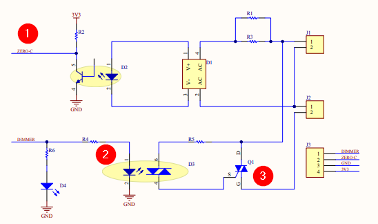
Sure, is what I did for the chinese SR clone I moded. You still have to add an optocoupler though, to separate the mains lines with high voltage through triac, from TC4 low voltage circuit. You can use the RobotDyn schematic for this job, they use a classic triac control. ~~~
renatoa attached the following image:
|
|
|
|
| renatoa |
Posted on 10/21/2022 1:52 AM
|
|
Administrator Posts: 3104 Joined: September 30, 2016 |
Quote Gullygossner wrote: Would the small resistance coil (I think it's 100ohm, but haven't measured) that is used for the voltage drop to the bridge rectifier contribute to the 230w when the unit is in cooling mode? The smaller resistance coil would be dropping the voltage 90v so would it be a straight portion where 120v=230w (resistance coil and motor power) so the resistance coil is displaying 172.5W making the current to the motor ~2A? That would make the motor power only 60W which seams low. That is ! So you don't have a true DC power source for your 30V DC motor, but a resistive (and power hungry) voltage reducing... Your math seems right, indeed 60W is questionable to lift 230 grams, but I seen 250 grams dancing with 75W, so why not... Well, in this case usage of a mosfet is out of discussion, what you read there as 30V with motor spinning will hit 120V when mosfet OFF, and will bur. You need triacs, as discussed above. Either the embedded triacs with associate ZC detector, either a robotdyn dimmer. |
|
|
|
| dwertz |
Posted on 10/21/2022 2:06 AM
|
|
Newbie Posts: 45 Joined: October 19, 2022 |
Cool, you already did it! I have not opened my unit up yet. But this guy did some reverse engineering. http://cholla.mmt...rcuit.html He claims that on the SR800, there are optocouplers on the power board. The logic board drives the optocouplers via open collector NPN transistors. If this is indeed the case, then you could probably just use an Arduino Nano with a couple NPNs tacked on. The collectors could just be connected to the collectors on the existing logic board. He also mentioned that the voltage regulator is pretty cheesy, so a resistor or two may need to be adjusted to get a little more power for the Nano. I think it could all be pretty clean. Just a little opening in the base for access to the USB connector. The same guy also has some scope captures where he recorded the TRIAC timing for the various fan and heat settings. http://cholla.mmt...k/signals/ Edited by renatoa on 10/21/2022 10:48 AM |
|
|
|
| renatoa |
Posted on 10/21/2022 2:14 AM
|
|
Administrator Posts: 3104 Joined: September 30, 2016 |
Great addition! With those findings, well... no need to add something! TC4 already features similar functionality transistors for SSR driving, and a SSR input is an optocoupler Attached is an excerpt of the SSR drivers area from TC4 shield ~~~
renatoa attached the following image:

Edited by renatoa on 10/21/2022 6:48 AM |
|
|
|
| Gullygossner |
Posted on 10/21/2022 7:25 AM
|
|
1/4 Pounder Posts: 95 Joined: January 06, 2019 |
Quote dwertz wrote: Cool, you already did it! I have not opened my unit up yet. But this guy did some reverse engineering. http://cholla.mmto.org/coffee/hack/circuit.html He claims that on the SR800, there are optocouplers on the power board. The logic board drives the optocouplers via open collector NPN transistors. If this is indeed the case, then you could probably just use an Arduino Nano with a couple NPNs tacked on. The collectors could just be connected to the collectors on the existing logic board. He also mentioned that the volage regulator is pretty cheesy, so a resistor or two may need to be adjusted to get a little more power for the Nano. I think it could all be pretty clean. Just a little opening in the base for access to the USB connector. The same guy also has some scope captures where he recorded the TRIAC timing for the various fan and heat settings. http://cholla.mmto.org/coffee/hack/signals/ Oh wow this is really good information. If I'm reading it correctly, one would only need 4 wires (heater command, fan command, grounds) to the tc4+ board and control would be complete? I suppose one could even grab 12v for power to the tc4+ if it had enough current. Edited by Gullygossner on 10/21/2022 7:51 AM |
|
|
|
| renatoa |
Posted on 10/21/2022 10:53 AM
|
|
Administrator Posts: 3104 Joined: September 30, 2016 |
Not THAT simple... The cholla page is textual descriptive, and no drawings... tells nothing about the nature of ZC, HTR and FAN commands, how compatible are with Arduino. You should clarify these by doing some forensic yourself. Also the command logic is unknown, where to connect the commands, to the SSR outputs of the TC4 shield, or the OT1/2 data pins of the Arduino. After all the above are clarified, you can attempt the first connections. |
|
|
|
| dwertz |
Posted on 10/22/2022 12:26 AM
|
|
Newbie Posts: 45 Joined: October 19, 2022 |
Quote renatoa wrote: TC4 already features similar functionality transistors for SSR driving, and a SSR input is an optocoupler ~~~ I was thinking the Nano with extra NPNs because of the tiny size. I do not know how much space is available inside the unit. But having the thermocouple interface on the TC4 is very attractive. It removes the need for the Phidget thermocouple module and hub. Can the Arduino with TC4 be USB powered? The Nano can be for sure. As a side note, I found out last night that Fresh Roast at one time offered a unit with USB control. Too bad they don't offer something similar today in the SR800 size. https://www.roastmasters.com/sr700.html renatoa, did you see the link with the oscilloscope screen shots? They do show the voltages for the trigger signals and the ZCD. But I agree completely, I won't be hooking anything up until I have a schematic of the power board. |
|
|
|
| renatoa |
Posted on 10/22/2022 3:03 AM
|
|
Administrator Posts: 3104 Joined: September 30, 2016 |
Didn't investigated too much the signals because they should be same as of any dimmer, i.e. a phase angle control. There is not much to innovate in this field, this method exists for many decades, even before transistors era motors were controlled using vacuum tubes with same logic. TC4 will provide same signals, or equivalent. Beyond USB power, there is an issue with Nano: due to smaller permanent storage memory is 0.51kB EEPROM, it is not capable to run TC4 software, that is already at limit with the 1kB of Uno... Sure, if you have programming skills, selecting only the necessary parts of code, and without buttons/display interface code... maybe you can fit in this space. |
|
|
|
| Gullygossner |
Posted on 10/22/2022 8:13 AM
|
|
1/4 Pounder Posts: 95 Joined: January 06, 2019 |
Quote dwertz wrote: Quote renatoa wrote: TC4 already features similar functionality transistors for SSR driving, and a SSR input is an optocoupler ~~~ I was thinking the Nano with extra NPNs because of the tiny size. I do not know how much space is available inside the unit. But having the thermocouple interface on the TC4 is very attractive. It removes the need for the Phidget thermocouple module and hub. Can the Arduino with TC4 be USB powered? The Nano can be for sure. As a side note, I found out last night that Fresh Roast at one time offered a unit with USB control. Too bad they don't offer something similar today in the SR800 size. https://www.roastmasters.com/sr700.html renatoa, did you see the link with the oscilloscope screen shots? They do show the voltages for the trigger signals and the ZCD. But I agree completely, I won't be hooking anything up until I have a schematic of the power board. The Arduino/TC4 is usb power yes. The TC4+ has some capacity to be powered by an external usb source with a built in voltage regulator but I think that is limited to 24V. The tc4 or tc4+ is designed to be an Uno shield so it really add's minimal size to the tc4 as is. https://imgur.com/Kel9KKa shows a photo of the SR800 power board removed and a uno/tc4 combo in it's place along with a SSR relay. I think even with the power board in place, there would be room for a uno/tc4 combo but it would probably also work well to just have a connector off the side of the unit that one plugged the relavent connections for the uno/tc4 into. |
|
|
|
| renatoa |
Posted on 10/22/2022 8:44 AM
|
|
Administrator Posts: 3104 Joined: September 30, 2016 |
Is not a SR800 in that picture, but a SR540, and source (of picture) is here: https://homeroast...ad_id=6556 No idea about SR machines size difference... SR800 could be bigger ... Edited by renatoa on 10/22/2022 8:50 AM |
|
|
|
| renatoa |
Posted on 10/22/2022 8:49 AM
|
|
Administrator Posts: 3104 Joined: September 30, 2016 |
A first good news... from the second oscilloscope screen shot, seems that the ZC signal is TC4 compatible, as shape, logic (polarity) and voltage (5V) So apparently you can use the Orange wire as is, without any conditioning, directly connecting to the INT_PIN of the TC4. For triacs control I need more, unfortunately... a bit of schematic of circuits around them. Or, the circuitry related to Yellow - heater command and Brown - fan wires. |
|
|
|
| Gullygossner |
Posted on 10/22/2022 9:12 AM
|
|
1/4 Pounder Posts: 95 Joined: January 06, 2019 |
Quote renatoa wrote: A first good news... from the second oscilloscope screen shot, seems that the ZC signal is TC4 compatible, as shape, logic (polarity) and voltage (5V) So apparently you can use the Orange wire as is, without any conditioning, directly connecting to the INT_PIN of the TC4. For triacs control I need more, unfortunately... a bit of schematic of circuits around them. Or, the circuitry related to Yellow - heater command and Brown - fan wires. Thank you for digging into this! I will open up my machine and try to take some photos and get information regarding the power board in the next day or two. |
|
|
|
| dwertz |
Posted on 10/22/2022 4:34 PM
|
|
Newbie Posts: 45 Joined: October 19, 2022 |
Out of curiosity I popped open my SR800 and took a look at the power control circuit.
Edited by renatoa on 10/25/2022 1:43 AM |
|
|
|
| dwertz |
Posted on 10/22/2022 11:36 PM
|
|
Newbie Posts: 45 Joined: October 19, 2022 |
Quote Gullygossner wrote: but it would probably also work well to just have a connector off the side of the unit that one plugged the relavent connections for the uno/tc4 into. Now that is an interesting idea. One would have to be careful, with the control lines exposed to a connector, someone could for instance short the heater command to ground without the fan on and smoke the heater. With the control logic inside the housing, there are fewer chances for mistakes like that. Also, I would definitely have the 1k resistor in series with the TRIAC driver inside the SR800. There are two options, tap into the wiring between the CPU board and the power board with the 1k resistors between the tap and the connector, or you could tap onto the CPU board at the NPNs and use the 1k on the CPU board. Personally, if I go this route, I will use the first approach. I don't know anything about the TC4/TC4+ firmware, but anything I use will have logic to prevent heater energization without the fan set to some minimum speed. Ideally you would have access to a temperature sensor that is tightly thermally coupled to the heater. That way you could detect heater overtemperature conditions in case of a fan failure or airflow restriction due to clogged chaff collector and shut down the heater. Perhaps one of these days I will open the unit back up and check out the built-in temperature sensor. |
|
|
|
| renatoa |
Posted on 10/23/2022 2:43 AM
|
|
Administrator Posts: 3104 Joined: September 30, 2016 |
Quote This looks directly compatible with OT1/2 outputs of TC4 shield, so again no need to change any bit, except the resistor, but lower value because we have 5V instead 12V. Typical Arduino schematics are using 220-330 Ohms for this task, to ensure a minimum of 10 mA for the optocoupler to fire. With 1kO the current will be about 3 mA, not enough. Except this, just handle the optocoupler inputs as a SSR in the TC4 schematic. |
|
|
|

| Jump to Forum: |
Powered by PHP-Fusion Copyright © 2024 PHP-Fusion Inc
Released as free software without warranties under GNU Affero GPL v3
Designed with ♥ by NetriXHosted by skpacman