
Login

Shoutbox
You must login to post a message.
renatoa
07/26/2024 3:49 PM
Bill grubbe and Jk, 
allenb
07/26/2024 5:15 AM
Spiderkw Welcome to HRO!

renatoa
07/24/2024 8:31 AM
ramiroflores and John123,

 ?
?
?renatoa
07/21/2024 1:18 AM
 , Luislobo
renatoa
07/19/2024 11:28 AM
Koepea,
Forum Threads
Newest Threads
Skywalker roaster modsBackground Roast Iss...
Hello from Arkansas
TC4ESP
Green coffee reviews
Hottest Threads
| Skywalker roaster... | [375] |
| TC4ESP | [115] |
| War on Farmers by... | [47] |
| Adventures in flu... | [26] |
| Hello! (soon) Roa... | [17] |
In Memory Of Ginny

Donations
Latest Donations
dmccallum - 10.00
JackH - 25.00
snwcmpr - 10.00
Anonymous - 2.00
Anonymous - 5.00
dmccallum - 10.00
JackH - 25.00
snwcmpr - 10.00
Anonymous - 2.00
Anonymous - 5.00
Users Online
Guests Online: 6
Members Online: 0
Total Members: 8,393
Newest Member: Bill grubbe
Members Online: 0
Total Members: 8,393
Newest Member: Bill grubbe
View Thread
Who is here? 1 guest(s)
 Using aArtisanQ_PID with an old TC4
|
|
| ETomczak |
Posted on 02/12/2023 3:53 PM
|
|
Newbie  Posts: 39 Joined: February 06, 2023 |
Hi,I was using the TC4 on a homebuilt roaster about 9 years ago, and have since disassembled that roaster, but I'm working on a new one. I'd love to use the old TC4 board and LCD I still have, but I'm not sure it's compatible with the latest firmwares folks have been working on. First off, I'm not really that savvy with this stuff, so forgive me if I'm missing simple stuff. The TC4 shield I have is v4.00. It's mounted on a standard Arduino Uno. My goal is to have the TC4 controlling just the heater on my new fluid bed roaster, and to be able to connect it to my computer via USB cable, but also have a potentiometer on the control panel so that I can also use the roaster in stand-alone mode. Right now I just have it hooked up to a basic SSR in "slow PWM" mode for testing, but I may go another route for heater control in the end. I've loaded aArtisanQ_PID version 6.8. I set several of the user.h options to the applicable values, and I have a 10k pot. I'm having two issues: -The heater control output only goes from 30% to 100%, and the 30% starts at the halfway point of the pot's turn. In other words, if I set the pot to 100%, I can turn it down slowly, and it will get to 30% by the halfway point in the rotation, then the last half of the rotation it just displays 0% -I only want to use the one potentiometer for the heater, so I disabled the second analogue input on line 83 of user.h. However if I do that, then the heater doesn't turn on at all, no matter where the pot is set. It just disables both of them, seemingly. The last piece to all of this is that the last time I used this board was 9 years ago, and I really don't remember what it's integrity is. I don't remember if I shorted anything out or made any mistakes with it, but that is a possibility. If anyone thinks this is the possible problem, then maybe I need a new TC4 board. Any help or thoughts on this are greatly appreciated! Thanks in advance. |
|
|
|
| greencardigan |
Posted on 02/12/2023 9:21 PM
|
 1 1/2 Pounder  Posts: 1185 Joined: November 21, 2010 |
I'm fairly sure a V4 board will still be compatible with the newer sketches. Confirm user.h for Code Download source // Heater and Fan Limits/Options Other ideas: Make sure you're using the correct analogue input pins. ANLG1 is for controlling OT1 which is typically the heater control. Make sure your POT is actually working correctly in the lower part of it's range. Check that it's a linear POT rather than a logarithmic POT. |
|
|
|
| renatoa |
Posted on 02/13/2023 2:46 AM
|
|
Administrator Posts: 3104 Joined: September 30, 2016 |
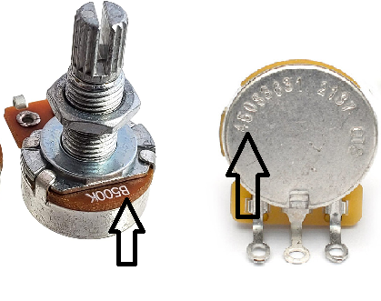
linear/log pot nature is marked with an A/B letter, as in the image below: The linear pots will output about 50% in the middle of rotation range, the log pots about 80/20% in the middle, i.e. 1/4 ratio between the two resistances.
renatoa attached the following image:
|
|
|
|
| randytsuch |
Posted on 02/13/2023 9:08 AM
|
 1/2 Pounder  Posts: 394 Joined: June 20, 2009 |
In the zip file I gave the link to before, go to ..\TC4-shield-master.zip\TC4-shield-master\hardware\TC4\TC4 V400 There is a BOM and schematic file there. |
|
|
|
| ETomczak |
Posted on 02/13/2023 11:31 AM
|
|
Newbie Posts: 39 Joined: February 06, 2023 |
greencardigan, First of all, thank you for all your work on this project! I'm excited to get it working, and I feel so lucky to be able to use the program you developed. I did check the code, and it looks just like you outlined, so that is not it. I also checked my pot, and it's acting normal except for at one end of it's range, but it doesn't change too much there, it's just a small deviation from 10k ohms. I will source another pot to check it out and see if I can fix it. Even if it was the pot, it doesn't explain why I can't disable ANLG2 without it disabling the whole board for some reason. renatoa, I did check and I do have a linear pot. It's working mostly correct, but I'll try to source another one just to make sure. randytsuch, That is so helpful! Thank you! I have two more blank TC4 shields, from ordering 3 at a time from OSHpark, so I might just order the components for those two, and solder up some extra boards. The more I've thought about it, the more I'm thinking that I might have shorted out the board I'm using by accident, and maybe that's even why I took it out of use years ago. Ok, I just tested it another way: I hooked up the pot to ANLG2 and disabled ANLG1 in the code, and it works like it's supposed to. I get 0% to 100% on FAN and heater just stays inactive. I'm really thinking it's the board now, replacing it will be my next step. Thanks everyone! I will report back after some new boards are soldered up. |
|
|
|
| randytsuch |
Posted on 02/13/2023 11:52 AM
|
|
1/2 Pounder Posts: 394 Joined: June 20, 2009 |
Quote ETomczak wrote: Ok, I just tested it another way: I hooked up the pot to ANLG2 and disabled ANLG1 in the code, and it works like it's supposed to. I get 0% to 100% on FAN and heater just stays inactive. I'm really thinking it's the board now, replacing it will be my next step. Thanks everyone! I will report back after some new boards are soldered up. That is strange to me. The analog inputs just provide a connector for an easy way to hook up a pot. Its just a connector and some traces to +5, ground and the arduino analog input 1 and 2. With a DVM, you can check if the pot wiper (pin 2 of ANLG1 or ANLG2) changes from 0 to 5VDC as you turn the pot. Just to double check the pot is working right, and the correct signal is going to the arduino. |
|
|
|
| renatoa |
Posted on 02/13/2023 12:40 PM
|
|
Administrator Posts: 3104 Joined: September 30, 2016 |
Or you can change in code, to have heater control coming from anlg2 instead ANLG1. Here: https://github.co...D.ino#L878 ... replace anlg1 with anlg2. |
|
|
|
| ETomczak |
Posted on 02/13/2023 1:50 PM
|
|
Newbie Posts: 39 Joined: February 06, 2023 |
randytsuch, I realized what you are saying after I posted my reply. I actually ordered another Arduino Uno R3 board, since I need a second one anyway and if anything is screwed up with reading an analog signal, it would be on the Uno itself, I think. I will track down my multimeter and test the voltage. renatoa: This is an interesting suggestion, so I tried it. Really odd result: now the FAN goes from 0% to 100% as normal (since it is still reading from anlg2 input) but heater stays at 0% until pot gets to halfway around, then they both read 50% and stay at the same reading from 50 to 100 . So maybe it is a software issue after all? |
|
|
|
| ETomczak |
Posted on 02/13/2023 2:54 PM
|
|
Newbie Posts: 39 Joined: February 06, 2023 |
Solved!!! The culprit was line 120 from user.h, it was the heater cutoff value in relation to the fan. It was set to 50 as default, I set it to 0 and all is good now. I connected the pot back to anlg1, disabled anlg2, and it's working great. I do have a new question now, unrelated somewhat. My vision for this roaster is to have a USB port that connects to the TC4, but also switches and potentiometers for both the fan and heater control. In a perfect world, I'd like for it to work like this: -If USB cable is NOT connected, then fan and heater are controlled by the on/off switches and pots. -If USB cable is connected, then the heater is controlled by Artisan on my computer. -I'd love to have a reset timer button as well, to reset the timer on the TC4, but it looks like I have to have the TC4 in "standalone" mode for this to work. And if it's in standalone mode, then it won't connect to Artisan when I plug it into the USB. Is there a way around this? I've already figured out that I can connect the on/off switch for the heater to the pot's 5v power source, and that way the heater displays 0% if the switch is OFF, then jumps straight to the set value when you switch it on. I'm now starting to consider using the TC4 for fan control as well, if I can get my hands on a Zero-cross detector from greencardigan. Unless, are there other zero-cross detectors out there I could use? Thanks! |
|
|
|
| greencardigan |
Posted on 02/13/2023 7:10 PM
|
|
1 1/2 Pounder Posts: 1185 Joined: November 21, 2010 |
Glad it was only a software setting! The pots will be active an all modes if you have them enabled. And you can probably tweak the code to check for one of the button presses. The risk with adding the button checking code is that the Arduino Uno's memory is quite full, and you may get random lockups if you push it too far. |
|
|
|
| renatoa |
Posted on 02/14/2023 1:51 AM
|
|
Administrator Posts: 3104 Joined: September 30, 2016 |
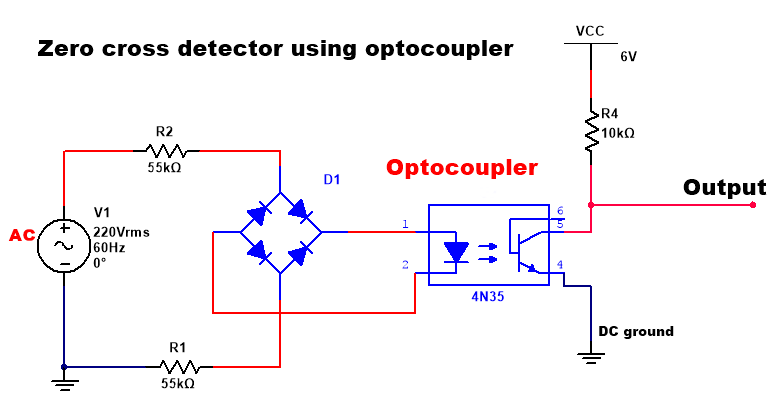
Quote ETomczak wrote: Solved!!! ... I set it to 0 and all is good now. ...Unless, are there other zero-cross detectors out there I could use? Thanks! Nope, not so good... for all machines... For a FB is mandatory to have airflow all time ! Some very concerned fellow on the forum even added secondary security measures, against the scenario of heater active with no airflow, i.e. ticking fire. A ZC detector can be done yourself with some cheap components, the schematic is attached below. The board linked by greencardigan is using same schematic.
renatoa attached the following image:
|
|
|
|
| ETomczak |
Posted on 02/14/2023 10:50 AM
|
|
Newbie Posts: 39 Joined: February 06, 2023 |
Quote renatoa wrote: Nope, not so good... for all machines... For a FB is mandatory to have airflow all time ! Some very concerned fellow on the forum even added secondary security measures, against the scenario of heater active with no airflow, i.e. ticking fire. A ZC detector can be done yourself with some cheap components, the schematic is attached below. The board linked by greencardigan is using same schematic. Don't worry, I have the safety logic hardwired into the actual controls of the machine. The heater simply won't turn on if the fan isn't running, and the fan has a minimum airflow set in the DC motor controller, so it's not possible to turn the heater on if the fan isn't running. I also have a mechanical contactor in addition to the SSR. I'd rather not trust that safety measure to software, but I'm sure it would be ok. I just realized something though. I have a pressure sensor sitting around that I took out of the blower of a furnace I was working on, and I could wire the safety so that it will only click the heat on if the blower is actually creating airflow. I really like that! It simplifies the wiring a bit too, and is even safer. I think I will just buy a ZCD from Brad, since he was nice enough to list them separately on his Tindie listing. I'd rather not pay that shipping charge, but I'm short on free time for this project, so a plug-and-play solution is better for me here. |
|
|
|

| Jump to Forum: |
Powered by PHP-Fusion Copyright © 2024 PHP-Fusion Inc
Released as free software without warranties under GNU Affero GPL v3
Designed with ♥ by NetriXHosted by skpacman