
Login

Shoutbox
You must login to post a message.
renatoa
07/26/2024 3:49 PM
Bill grubbe and Jk, 
allenb
07/26/2024 5:15 AM
Spiderkw Welcome to HRO!

renatoa
07/24/2024 8:31 AM
ramiroflores and John123,

 ?
?
?renatoa
07/21/2024 1:18 AM
 , Luislobo
renatoa
07/19/2024 11:28 AM
Koepea,
Forum Threads
Newest Threads
Skywalker roaster modsBackground Roast Iss...
Hello from Arkansas
TC4ESP
Green coffee reviews
Hottest Threads
| Skywalker roaster... | [375] |
| TC4ESP | [115] |
| War on Farmers by... | [47] |
| Adventures in flu... | [26] |
| Hello! (soon) Roa... | [17] |
In Memory Of Ginny

Donations
Latest Donations
dmccallum - 10.00
JackH - 25.00
snwcmpr - 10.00
Anonymous - 2.00
Anonymous - 5.00
dmccallum - 10.00
JackH - 25.00
snwcmpr - 10.00
Anonymous - 2.00
Anonymous - 5.00
Users Online
Guests Online: 4
Members Online: 0
Total Members: 8,393
Newest Member: Bill grubbe
Members Online: 0
Total Members: 8,393
Newest Member: Bill grubbe
View Thread
Who is here? 1 guest(s)
 Skywalker roaster mods
|
|
| renatoa |
Posted on 01/03/2024 11:49 AM
|
|
Administrator Posts: 3104 Joined: September 30, 2016 |
Everyone has personal preferences, based on specific restrictions and past experience. A lot of things could go wrong with a tethered setup. Even worse with the wireless ones. It always helps to have a manual override handy, just in case. |
|
|
|
| darelleman |
Posted on 01/03/2024 2:50 PM
|
|
Newbie  Posts: 5 Joined: December 30, 2023 |
For the reasoning I would have to agree with renatoa. As this is my first roaster I think it would be an interesting first step to see how the Skywalker runs its auto & assisted roast profiles. This would also help us as a community better understand how the machine operates. That also makes it easier for people to use those profiles as a starting point to start controlling the roaster via artisan. I would be happy to do the testing and am plenty handy with soldering and making cables. My preference would be if we could find a way to implement this without needing to modify the roaster hardware itself. I think that makes it more approachable for less technical folks. Basically if you could just throw in some sort of USB splitter and connect both the Arduino and controller screen that would be pretty easy for people to do. Note: I am not sure a standard usb splitter would work because due to usb protocol a usb splitter usually has one side be power only (2 wires) and the other have communication and power (4 wires). Since we need all 4 wires connected to both I am not sure an off the shelf splitter will work. |
|
|
|
| sloppyjosh |
Posted on 01/03/2024 9:42 PM
|
|
Newbie Posts: 30 Joined: December 01, 2023 |
Quote renatoa wrote: Quote sloppyjosh wrote: ...I soldered wires to the RX, TX, and Ground of the controller board. So I can plug those in to my logic analyzer or an arduino to sniff the data. ... What is peak voltage of the data pulses, 5v (Arduino) or 3.3v (ESP) ? 5v is what I was seeing, I believe. I was just using a cheap logic analyzer |
|
|
|
| sloppyjosh |
Posted on 01/03/2024 9:45 PM
|
|
Newbie Posts: 30 Joined: December 01, 2023 |
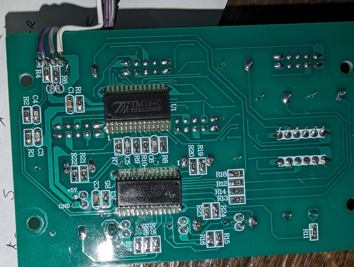
Quote renatoa wrote: Sounds possible, you connect only the control panel receiving wire to Arduino, and let them talk undisturbed. This way you would just spy the temperature evolution, and plot in Artisan, with a much better RoR following. Someone could go even further, and spy both wires, i.e. having two input/read pins, instead a Rx/Tx pair. The second Rx pin would be to monitor the messages sent by control panel to the roaster, the purpose being to capture even the power/fan changes, and log them in Artisan. This implies some changes in the original josh source, not rocket science, but time for tests is needed, and an Arduino available for this job. I can sketch this code if Josh isn't listening or busy to do this fork of the original project, but all testing will be up to whoever is interested in it. Sorry.. have been busy with holidays, work, family.. etc..etc..ya'll know the drill. I have code for this.. It's in the repository called SkywalkerSpy... You tap on to the two data lines and the ground between the roaster and the controller.. then it takes turns reading and decoding a packet from the roaster, then a packet from the controller.. It just replies to any serial input with the current state. I wasn't quite sure how to get artisan to read it so I just wrote a little python program to do the serial part and let artisan interact with that as a command. It worked pretty well. Edit -- Added a picture showing how I tapped the lines.. This is on my controller and I just squeezed those three lines out with the other cable. Though, if you had parts available, it'd be really easy to build with USB ports that would let you attach/detach as you want. If they ever send me another board I'd really like to do some more work on polishing all that stuff up.. But I can't do much without their controller board.
sloppyjosh attached the following image:
Edited by sloppyjosh on 01/03/2024 9:54 PM |
|
|
|
| darelleman |
Posted on 01/03/2024 10:52 PM
|
|
Newbie Posts: 5 Joined: December 30, 2023 |
Thanks sloppyjosh! I took my controller apart and unfortunately they aren’t using standard USB color coded cables. Do you know what the pin out of the controllers usb connector is? And which digital pin on the Arduino is the Rx line and which is Tx? From there I should be able to make a usb Y-cable that connects them both at the same time. |
|
|
|
| renatoa |
Posted on 01/04/2024 2:29 AM
|
|
Administrator Posts: 3104 Joined: September 30, 2016 |
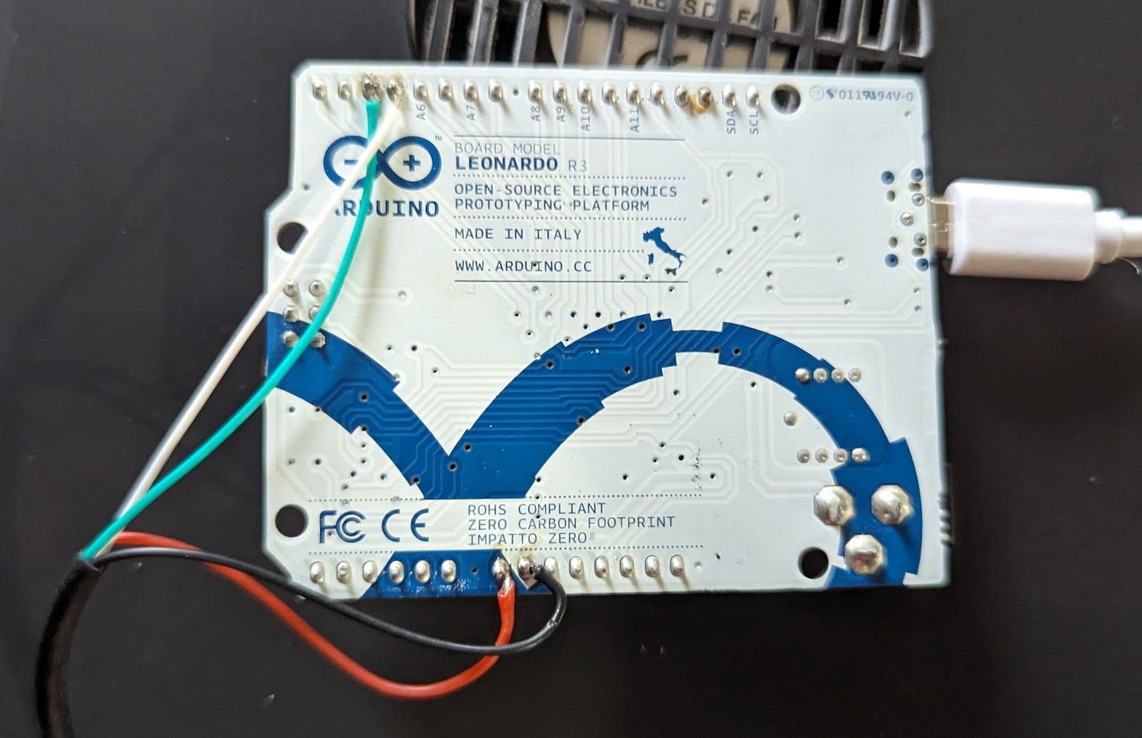
For the Skywalker spy project color doesn't matter, you identify them by message content, the one with temperature is from the roaster, the other with commands is from controller. Also, the picture from github could give you a hint, check attached. As a reminder, the project page is here: https://github.co...kerRoaster
renatoa attached the following image:
|
|
|
|
| renatoa |
Posted on 01/04/2024 2:47 AM
|
|
Administrator Posts: 3104 Joined: September 30, 2016 |
Quote darelleman wrote: For the reasoning I would have to agree with renatoa. As this is my first roaster I think it would be an interesting first step to see how the Skywalker runs its auto & assisted roast profiles. This would also help us as a community better understand how the machine operates. That also makes it easier for people to use those profiles as a starting point to start controlling the roaster via artisan. The automatic profiles were already deciphered and described in main skywalker thread. Posting again here for your convenience: Preheat temperature: 200C for naturals (1x profiles), 220C for washed (2x), 215 for honey (3x) Start power: 65% for naturals (1x profiles), 70% for washed (2x), 65% for honey (3x) At 170C power reduced to: 40% for naturals (1x profiles), 50% for washed (2x), 45% for honey (3x) drop temperature is according table in manual, and second profile digit: light/medium/dark Fan start value 65% for all profiles, pushed to 90% at 170-172C. It's a fixed matrix of values, nothing changes according to roasting progress feedback or machine load. Edited by renatoa on 01/04/2024 3:18 AM |
|
|
|
| darelleman |
Posted on 01/04/2024 7:55 AM
|
|
Newbie Posts: 5 Joined: December 30, 2023 |
Quote renatoa wrote: For the Skywalker spy project color doesn't matter, you identify them by message content, the one with temperature is from the roaster, the other with commands is from controller. Also, the picture from github could give you a hint, check attached. As a reminder, the project page is here: https://github.co...kerRoaster Color doesn’t matter but Pinout on the USB does, only reason I mention color is because USBs have standardized cable color coding so you know which cable goes to which pin and what that cable does. The only tidbit of information missing from the GitHub is which digital pin is Rx and which is Tx. From there, because of the standard color coded USB cable in the picture I can work out the usb pin out. |
|
|
|
| renatoa |
Posted on 01/04/2024 8:54 AM
|
|
Administrator Posts: 3104 Joined: September 30, 2016 |
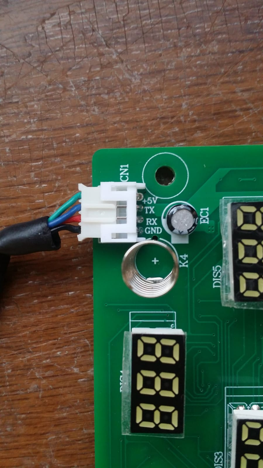
Yeah, you have a good reason to be worried... the chinese made a mess with the usb cable wires, as you see in the picture attached. The only wire that match the color with function is black = ground. All the others are different. The good news is that they kept the order, it's the same on both ends of the cable...... usb contacts are the same as the PCB connector. BTW, the connector is not using the ubiquitous 2.54 pitch, as all the test boards, but 2mm pitch, you need special pins to experiment without soldering on the control panel PCB. ~~~
renatoa attached the following image:
Edited by renatoa on 01/04/2024 8:59 AM |
|
|
|
| sloppyjosh |
Posted on 01/05/2024 10:53 PM
|
|
Newbie Posts: 30 Joined: December 01, 2023 |
Quote darelleman wrote: Quote renatoa wrote: For the Skywalker spy project color doesn't matter, you identify them by message content, the one with temperature is from the roaster, the other with commands is from controller. Also, the picture from github could give you a hint, check attached. As a reminder, the project page is here: https://github.co...kerRoaster Color doesn’t matter but Pinout on the USB does, only reason I mention color is because USBs have standardized cable color coding so you know which cable goes to which pin and what that cable does. The only tidbit of information missing from the GitHub is which digital pin is Rx and which is Tx. From there, because of the standard color coded USB cable in the picture I can work out the usb pin out. Sorry I forgot to add info about which pin is which.. And at the moment I can't remember. It's written on a note on my desk that I can't get to at the moment... I'll try to remember to add some documentation to that. As renatoa noted, the data is on the center two pins.The arduino is just listening to those when using Skywalker Spy.. So if you try them one way and things don't seem to work.. just swap the pins. |
|
|
|
| sloppyjosh |
Posted on 01/05/2024 10:58 PM
|
|
Newbie Posts: 30 Joined: December 01, 2023 |
I put an acrylic front on the roaster and put 225, 340, and 455 grams of beans in to see where the probe would sit in relation to the bean mass... IMO, this may be the culprit for why the temps seem to read low. See what ya'll reckon.. I'll probably have the clear front on it a bit longer so if you want to see anything else that I didn't do in the video let me know and I'll try to do it. |
|
|
|
| amaller |
Posted on 01/06/2024 12:01 AM
|
|
Newbie Posts: 8 Joined: January 05, 2024 |
Quote sloppyjosh wrote: I put an acrylic front on the roaster and put 225, 340, and 455 grams of beans in to see where the probe would sit in relation to the bean mass... IMO, this may be the culprit for why the temps seem to read low. See what ya'll reckon.. I'll probably have the clear front on it a bit longer so if you want to see anything else that I didn't do in the video let me know and I'll try to do it. At least with my fluid bed roaster, by the end of the roast the volume of beans in the chamber is significantly more. Almost double. I would expect the probe to be more submerged towards the end of the roast due to lower bean density. |
|
|
|
| sloppyjosh |
Posted on 01/06/2024 12:06 AM
|
|
Newbie Posts: 30 Joined: December 01, 2023 |
Quote amaller wrote: Quote sloppyjosh wrote: I put an acrylic front on the roaster and put 225, 340, and 455 grams of beans in to see where the probe would sit in relation to the bean mass... IMO, this may be the culprit for why the temps seem to read low. See what ya'll reckon.. I'll probably have the clear front on it a bit longer so if you want to see anything else that I didn't do in the video let me know and I'll try to do it. At least with my fluid bed roaster, by the end of the roast the volume of beans in the chamber is significantly more. Almost double. I would expect the probe to be more submerged towards the end of the roast due to lower bean density. Excellent point! I have about 1lb of roasted beans.. I'll put them in there tomorrow and see what it looks like. |
|
|
|
| Mike_Mathis |
Posted on 01/06/2024 12:23 AM
|
|
1/4 Pounder  Posts: 125 Joined: August 06, 2019 |
Thanks Josh for the video. I ordered a thermocouple today to add to the existing one for Artisan data. I will also move the original one while I am in there. I'm thinking between your two lower dots and just above fin clearance is the place to relocate the original. I would be interested to know the measurement in mm from the center of the stock location to the center of your 340 mark. This will help me decide where to locate my add-on probe. Standard would be ok too. I can convert. I'm beginning to view you as a roaster surgeon. Edited by Mike_Mathis on 01/06/2024 9:34 AM *Kaffelogic Nano 7
*Skywalker V1 *2023 BC-2 |
|
|
|
| renatoa |
Posted on 01/06/2024 3:10 AM
|
|
Administrator Posts: 3104 Joined: September 30, 2016 |
Imo, the deeper the probe is in bean mass, the lower (and slower) will be the reading. There is no need the probe to be completely into beans. In commercial roasters you could see probes in apparently abnormal positions, where they read almost half air, and the users seems be ok with those approaches. During my TO experiments I found that a probe not touching anything, at 3-4 mm above beans bed shows the same values as one completely immersed into beans. But the probe above beans signals faster the coming events, like TP/FC, than the inner probe. This is not a claim that they "designed" this machine scientifically, and the probe location is ideal, so don't touch it... but I am skeptical that looking for other location would improve something. Surely would not bring the temperature range back to where the people is accustomed, with FC at 200C/400F, nor allow to compare profiles with those from other non-radiant machines. |
|
|
|
| Mike_Mathis |
Posted on 01/06/2024 9:20 AM
|
|
1/4 Pounder Posts: 125 Joined: August 06, 2019 |
renatoa, Considering the controller is tuned to actions for the current location of "their" probe, I will leave it be. When my 4mm X 30mm probe comes in I'll decide where to install it. I only plan to use it for data recording anyway. I am curious to see the difference and will pass this info here through Artisan graphs. Works well to pour beans in Skywalker. 
Edited by Mike_Mathis on 01/06/2024 11:45 AM *Kaffelogic Nano 7
*Skywalker V1 *2023 BC-2 |
|
|
|
| HarryDog |
Posted on 01/06/2024 9:54 AM
|
 1/2 Pounder  Posts: 349 Joined: July 20, 2022 |
Hello Josh, great video, can see lots but where is the lamp positioned? Test with a blacked area to represent the lamp will help me see how much if any I can increase drum speed. When your motor is on high, what voltage is that? Max 24vdc? Would like to see the spray of beans at max to see if they would be hitting the lamp. I'm not an expert in thermodynamics (If that's the correct term) but I think this lamp cooks differently, the temp at which it penetrates the beans enough to roast them, so the result is a different temp. Next I don't know how accurate the stock probe is? Is it a thermistor? Using a Bing search they say most use a range to 130C, next better option might be an RTD? After seeing the video I think charges of 400g might be much better for auto mode? Rather then moving the probe? Need to test this out. |
|
|
|
| renatoa |
Posted on 01/06/2024 12:49 PM
|
|
Administrator Posts: 3104 Joined: September 30, 2016 |
There are NTC that perform well in an operating range up to 250°C. Seems to be NTC, based on the data collected by josh, assuming there isn't a voltage polarity inversion somewhere in the processing chain. Want to test probe accuracy ? Remove it and do a boiling water test, 100C is 100C... at least at sea level  |
|
|
|
| Dan N |
Posted on 01/06/2024 1:01 PM
|
|
Newbie Posts: 28 Joined: January 06, 2024 |
Quote sloppyjosh wrote: It says FMD N3hWIKH FMD is a chip manufacturer that makes a few microcontrollers but I couldn't find any data sheet that looked like it matched the chip itself. It looks like a Fremont Micro Devices PIC clone with the part # etched off (middle line between FMD and bottom production code). Probably similar to FT61F023. lcsc.com has FMD datasheets for 7 SOIC-16 parts and all have the same pinout. |
|
|
|
| Dan N |
Posted on 01/06/2024 1:06 PM
|
|
Newbie Posts: 28 Joined: January 06, 2024 |
Quote sloppyjosh wrote: The readings from the roaster are inversely proportional to the temps but I haven't put a meter directly on the probe. I used a 4th degree polynomial and got it working pretty well. Here's a code suggestion to increase efficiency. Since the Arduino AVR processor doesn't have hardware FPU, the floating-point operations are emulated by software and take a lot of cycles. I used Horner's Rule to rearrange that polynomial and reduce the number of multiplies from 40 to 14: Code Download source v = 583.1509258523457 + Thanks for your amazing work! |
|
|
|
| renatoa |
Posted on 01/06/2024 1:34 PM
|
|
Administrator Posts: 3104 Joined: September 30, 2016 |
Since the NTC resistance to temperature variation rule is logarithmic (recheck post #22), the reverse we are trying to simulate should be an exponential. I would dig in this direction too. |
|
|
|
| Dan N |
Posted on 01/07/2024 5:11 PM
|
|
Newbie Posts: 28 Joined: January 06, 2024 |
The way the S-curves on the graph in post #22 shift over and change slope matches graphs I've seen that plot thermistor volts vs temp for different series resistor values. I believe R16 (2k) is connected to a digital i/o which can be set to do 3 different things:
It's likely they measure with R16 floating and again with R16 active. This could be verified by scoping R16 on the processor side. |
|
|
|
| Dan N |
Posted on 01/08/2024 11:37 AM
|
|
Newbie Posts: 28 Joined: January 06, 2024 |
I can calculate the series resistor value from the data in post #3 and the 1st reading does appear to use 1875 ohms for the high temperatures. I assume the 2nd reading uses 30k because it is the smallest at high temp. Rt should be equal for both readings, solving for Rs gives: Rs = 30000 * (1023/d1 - 1) / (1023/d2 - 1) 264,22, 429 Rs = 30000 * (1023/264 - 1) / (1023/22 - 1) = 1895.6 ohm |
|
|
|
| Robotic Kitten |
Posted on 01/08/2024 9:59 PM
|
|
Newbie Posts: 24 Joined: December 04, 2023 |
@sloppyjosh I have a question about about this section of the codehttps://github.co...#L232-L236 Can an "unsigned long" be "negative"? Assuming, the "overflow", maybe do the following? Code Download source if (now < time) {and a second question: the isbeingtoolong() , is it for "artisan" commands timeout? i.e. if not hearing from artisan for 10s then shut everything down? |
|
|
|
| renatoa |
Posted on 01/09/2024 5:52 AM
|
|
Administrator Posts: 3104 Joined: September 30, 2016 |
About the second... seems so, time is initialized after handling each serial command coming from the operator. Code Download source time = micros(); "Operator" meaning not necessary only Artisan, TC4 commands can be sent from a terminal application, by typing them, as in a Linux shell. Is debatable if abandoning roast is a great idea... if Artisan is broken, and also no control panel present. Maybe the last heater power/fan levels could be preserved, and let the human operator decide drop based on smell/vision, thus saving the roast... if the human operator is still nearby and able to operate the machine... Also, I wonder where is the 230C shutdown implemented, in the control panel or in the roaster controller... in the second case this protection being still active even if using Artisan... About the first, usually overflows should be foreseen and handled in code. Like a division by zero error for example... a wise programmer should always check is the divisor is not zero ;) |
|
|
|

| Jump to Forum: |
Powered by PHP-Fusion Copyright © 2024 PHP-Fusion Inc
Released as free software without warranties under GNU Affero GPL v3
Designed with ♥ by NetriXHosted by skpacman