
Login

Shoutbox
You must login to post a message.
renatoa
07/26/2024 3:49 PM
Bill grubbe and Jk, 
allenb
07/26/2024 5:15 AM
Spiderkw Welcome to HRO!

renatoa
07/24/2024 8:31 AM
ramiroflores and John123,

 ?
?
?renatoa
07/21/2024 1:18 AM
 , Luislobo
renatoa
07/19/2024 11:28 AM
Koepea,
Forum Threads
Newest Threads
Skywalker roaster modsBackground Roast Iss...
Hello from Arkansas
TC4ESP
Green coffee reviews
Hottest Threads
| Skywalker roaster... | [375] |
| TC4ESP | [115] |
| War on Farmers by... | [47] |
| Adventures in flu... | [26] |
| Hello! (soon) Roa... | [17] |
In Memory Of Ginny

Donations
Latest Donations
dmccallum - 10.00
JackH - 25.00
snwcmpr - 10.00
Anonymous - 2.00
Anonymous - 5.00
dmccallum - 10.00
JackH - 25.00
snwcmpr - 10.00
Anonymous - 2.00
Anonymous - 5.00
Users Online
Guests Online: 4
Members Online: 0
Total Members: 8,393
Newest Member: Bill grubbe
Members Online: 0
Total Members: 8,393
Newest Member: Bill grubbe
View Thread
Who is here? 1 guest(s)
 MCP3424 on TC4 blowing
|
|
| pjvdl |
Posted on 04/27/2021 7:50 PM
|
 Newbie  Posts: 38 Joined: April 05, 2020 |
I have an interesting problem with the MCP3424 ADC chip on my TC4 board blowing up. I have now blown 6 or 7 MCP3424 chips while trying to isolate the problem, although interestingly it is only ever the MCP3424 chip that blows. The rest of the TC4 board and carrier arduino continue to operate correctly (on each occassion I have tested the I2C bus separately to confirm that the MCP9800 chip is still operational as well). My setup is a 1kg drum roaster with:
You can find more about my build at https://homeroast...ad_id=6334. During a couple of early tests of the system I noted fluctuations in temperature readings when I turn the drum motor on or off. The motor is drawing around 4A @ 12V In a steady state, but I think it may be pulling up to 15A transient on startup. This is difficult to ascertain though, as my multimeter doesn't have the response times to see the transient currents accurately. My working theory is that electro-magnetic interference from the heater and/or motor are causing excessive voltage in the thermocouple input, which exceeds the input rating of the MCP3424 inputs. This seems to be supported by my above observation that the temperature readings fluctuate more as the motor is turned on/off, because of the current transients that occur. To address this, I have:
Having made these changes, I no longer see any temperature reading fluctuations. This seems to indicate I am not getting voltage spikes any more, but in spite of this, I have still blown a couple of MCP3424's. At the moment the thermocouple wires run inside the chassis of the drum roaster, so they are still within 60 - 70mm of the heater and the heater. This may still be too close, so I think the next step will be to temporarily remove the wires to run them externally as a test. Other than that, I am out of ideas. If anyone has seen this type of issue, I would very much appreciate some suggestions for how to solve it! Edited by pjvdl on 04/27/2021 8:35 PM -- Paul
ECM Rocket espresso Eureka Mignon grinder 500g BBQ rotisserie roaster 1kg drum roaster |
|
|
|
| greencardigan |
Posted on 05/05/2021 11:53 PM
|
 1 1/2 Pounder  Posts: 1185 Joined: November 21, 2010 |
I'm not sure what's causing your issue. For the TC4s I build, I use 10,000pF caps across each input and also between each input pin and ground. So 12 caps in total. No idea if this would help your issue though. |
|
|
|
| renatoa |
Posted on 05/06/2021 6:22 AM
|
|
Administrator Posts: 3104 Joined: September 30, 2016 |
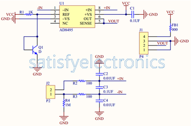
Attached is the typical schematic of a dedicated TC amplifier circuit. The lower part is the input filtering, good as start for virtually any TC interface ICs. Me too I blown a circuit as above, but was a serious overvoltage, between the naked junction and the oven case, ungrounded, that also thrilled me when touching. Electromagnetic interference are not a concern, using happily unshielded probes at 20 cm near two motors. ...
renatoa attached the following image:
|
|
|
|
| mg512 |
Posted on 05/06/2021 8:05 AM
|
 1/4 Pounder  Posts: 189 Joined: March 04, 2018 |
I've occasionally seen the MCP3424 blow on the TC4+, and I also heard from JimG that this happened on the original TC4 sometimes as well. That said, I was never able to figure out with certainty what's causing it, as it never happened in my own tests or usage, only ever with customers. I've never seen it happen multiple times with the same customer though. Recently I've added TVS diodes to the TC inputs on the latest version of the TC4+, which would help if users accidentally shorted a >5V signal to one of the TC inputs. I haven't seen any blown chips since that change, but it's been very recent, and it was only ever a very infrequent thing to begin with, so can't conclude anything with certainty yet. Are you using a TC4 or TC4+? If it's a TC4+, I'd be happy to send you another one from the latest batch just to see if it makes a difference. I would in any case also triple and quadruple check that nothing touches anything anywhere that could in turn touch anything that has more than 5 volts on it. That includes the metal shielding of the TC wires, which could easily make (even intermittent) contact with the screw terminals on the TC4/TC4+. |
|
|
|
| JackH |
Posted on 05/06/2021 5:08 PM
|
 Administrator Posts: 1809 Joined: May 10, 2011 |
Are you using grounded or ungrounded probes? I seem to remember a problem in the past with grounded probes since the wires are physically attached to the inside of the probe wall. The temperature readings were very unstable. Ungrounded are electrically isolated from the sheath but are slower to respond.
---Jack
KKTO Roaster. |
|
|
|
| pjvdl |
Posted on 05/06/2021 11:44 PM
|
|
Newbie Posts: 38 Joined: April 05, 2020 |
Thanks all for your input. Attempting to respond to your suggestions.: I have 10uF caps between the inputs and ground, but not between the inputs themselves. I think I will look at adding these just in case. I am using ungrounded k type probes, so hopefully the grounding isn't a problem. I was using a TC4+, but was having issues getting a new one last year, so ended up designing my own clone of the TC4. I agree that I need to check voltages again. This remains, in my view, one of the most likely causes. Thanks again all. Will keep you posted with progress. -- Paul
ECM Rocket espresso Eureka Mignon grinder 500g BBQ rotisserie roaster 1kg drum roaster |
|
|
|
| renatoa |
Posted on 05/07/2021 1:17 AM
|
|
Administrator Posts: 3104 Joined: September 30, 2016 |
The caps value should be 10 nF = nano, not uF = micro. Is not about the value itself, but technology, the capacitors in the micro Farad ballpark are usually electrolytic, with internal leakages that could affect reading precision. Ungrounded aren't slower by default, is the sheath that give the most of the measurement speed. If you have the skills to build yourself a TC4, then you could consider an architecture change, with dedicated TC amps before the MCP DAC, as in the picture attached some posts above. This solution is inspired (but not copied  ) from Phidgets architecture, and based on my experience is better than original TC4 solution, as precision, stability and speed. ) from Phidgets architecture, and based on my experience is better than original TC4 solution, as precision, stability and speed. Not the last, is fully supported by current TC4 firmware, changes in code being minimal. Edited by renatoa on 05/07/2021 1:26 AM |
|
|
|
| JackH |
Posted on 05/07/2021 3:56 AM
|
|
Administrator Posts: 1809 Joined: May 10, 2011 |
Quote renatoa wrote: Ungrounded aren't slower by default, is the sheath that give the most of the measurement speed. Not according to the Omega site. 
---Jack
KKTO Roaster. |
|
|
|
| renatoa |
Posted on 05/07/2021 4:21 AM
|
|
Administrator Posts: 3104 Joined: September 30, 2016 |
404 Not Found Incomplete link it seems. I think I found the primary source of this info: Quote How do I know which junction type to choose? Sheathed thermocouple probes are available with one of three junction types: grounded, ungrounded or exposed. At the tip of a grounded junction probe, the thermocouple wires are physically attached to the inside of the probe wall. This results in good heat transfer from the outside, through the probe wall to the thermocouple junction. In an ungrounded probe, the thermocouple junction is detached from the probe wall. Response time is slower than the grounded style, but the ungrounded offers electrical isolation. https://www.omega...uples.html ... the confusion could come from the different meanings we have for the "grounded" term, related to the sheath or to the wires. Or even to the junction itself. I am using the grounded term as a substitute for shielded wires, in a metal mesh, not for the probe itself. Shielded wires were those who gave me headaches so far, as you already posted above. From what I tested to date, an exposed junction has the fastest response, but is so nervous that it really needs some sort of sheath to calm down a bit the response time, else the results are useless noise. Here is the part were we can debate about grounding... it is good or not to have junction/wires touch the sheath ? should be the sheath metal be grounded or not... etc... Edited by renatoa on 05/07/2021 7:27 AM |
|
|
|
| FriendlyFire |
Posted on 05/12/2022 1:09 AM
|
|
Newbie Posts: 9 Joined: February 16, 2022 |
I just got my TC4+ up and running and was on my 4th batch when I saw a puff of smoke come from the MCP3424 chip and the BT reading went to a negative 5-figure value. I didn't see any opportunity for a short but will look under magnification tomorrow to make sure. I read the above thread but don't understand the suggestion people have made about putting a 10nF capacitor between the inputs and ground. Can someone explain this? As for what to do next, do you think I could use a regular, wide soldering tip to unsolder the old 3424 and put in a new one or will I have to buy a reflow gun? Also, if replacing the chip is the best way forward (and I think it is), wouldn't it be better to solder in a 14 pin, 2-row socket and then bend the gull-wing pins of the new chip down to fit into it? That way if it burns out again, the replacement is easy to do. Thank you. Edited by FriendlyFire on 05/12/2022 1:35 AM |
|
|
|
| renatoa |
Posted on 05/12/2022 2:57 AM
|
|
Administrator Posts: 3104 Joined: September 30, 2016 |
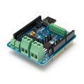
You can use the MCP3424 on a board assembly, that I used for TC4ESP project, something like this: https://www.ebay....3990741705 Attached a picture, to remain here as an example, because ebay pages are volatile in time. Your accident I think is due to the TC metal in contact with a non grounded part of your roaster, that could have leaks to live mains line. The capacitors should be already there on TC4 board, and would not help in any scenario that led to puffing a chip. They help mostly for high frequency noise. A regular soldering tool could be good for removing the damaged chip, but you need a very sharp tip to solder back a good one. The pins pitch is 0.5 tenth of an inch ! Also, if tip is overheated you have great chances to exfoliate the PCB traces, damaging board even more. Instead buying a reflow tool only for this job, plus magnifying glasses, plus reflow paste... plus... I would rather ask for this operation done in a cell phones repair/service shop, they have the right tools and skills for jobs of this fineness level. ~~~
renatoa attached the following image:

Edited by renatoa on 05/12/2022 3:07 AM |
|
|
|
| FriendlyFire |
Posted on 05/12/2022 4:22 PM
|
|
Newbie Posts: 9 Joined: February 16, 2022 |
Thanks, Renatoa! What temp should I use to unseat and replace the chip? I have a dissection scope (and magnifying glasses), reflow paste, and a Hakko soldering iron. I agree that the work is fine but I want to use the hiccups in this process to improve my knowledge and skill in electronics, so I'm willing to risk it. I found a $50 reflow tool on Amazon. Is that the preferred method for removing and replacing this chip? You bring up a good point - the TCs are directly screwed into the body of the popcorn popper chamber, which is not grounded. That said, I can use the ground wire from the three-prong plug and attach it to a screw on the body if you think it's necessary - no one addressed this in any of the instructions I read, so I didn't preemptively do it. Also, is there such a thing as a protective, low, low current fuse that could be put in line of the TCs so I can't, under any circumstances, burn out the chip again? Thank you for your valuable insights and for the suggestion for the MCP3424 chip. I assume you're suggesting I remove the chip from that board and replace it on the TC4+ right? |
|
|
|
| greencardigan |
Posted on 05/12/2022 8:53 PM
|
|
1 1/2 Pounder Posts: 1185 Joined: November 21, 2010 |
I would try to cut each individual pin on the MCP3424 with some sharp flush cutters to remove it. Then remove the remaining part of each pin individually with the soldering iron. And you should be able to solder in a new MCP3424 even with a mid-sized tip. There's plenty of youtube vids showing various methods. Use a multimeter in continuity mode to confirm each pin is connected to the board and also not shorted to adjacent pins. |
|
|
|
| FriendlyFire |
Posted on 05/12/2022 9:49 PM
|
|
Newbie Posts: 9 Joined: February 16, 2022 |
I'm honored to have a reply from the Master himself! Thank you! I like that idea a lot and it obviates the need for me to buy more equipment that I probably wouldn't use much. I was also wondering if the now-burned-out chip on the board could be bypassed by connecting the individual leads to the available headers perhaps via a premade board like Renatoa, as I'm sure you saw, suggested. Please forgive this beginner question but what temperature should I set the iron to when doing this repair? I have it at 720F currently. |
|
|
|
| FriendlyFire |
Posted on 05/12/2022 10:34 PM
|
|
Newbie Posts: 9 Joined: February 16, 2022 |
Just in case the more experienced folks here can divine a cause from photos, I took pictures but have tried uploading them under "Attachment" and they don't show up for some reason. |
|
|
|
| greencardigan |
Posted on 05/12/2022 11:02 PM
|
|
1 1/2 Pounder Posts: 1185 Joined: November 21, 2010 |
Haha, I am definitely not the master! I just picked up the reins where the original maker (JimG) left off. I had only basic soldering skills when I started building boards and had never touched a surface mount component. I typically have my hakko888 set on 350C (but remember I'm not the master ) |
|
|
|
| FriendlyFire |
Posted on 05/12/2022 11:09 PM
|
|
Newbie Posts: 9 Joined: February 16, 2022 |
Quote greencardigan wrote: Haha, I am definitely not the master! I just picked up the reins where the original maker (JimG) left off. I had only basic soldering skills when I started building boards and had never touched a surface mount component. I typically have my hakko888 set on 350C (but remember I'm not the master )LOL. That's good enough for me. :-) |
|
|
|
| renatoa |
Posted on 05/13/2022 2:40 AM
|
|
Administrator Posts: 3104 Joined: September 30, 2016 |
Do you mean solder tool tip temperature, or hot air temperature ? 350C or 350F ? The typical PCB circuits allows maximum 240-250C for 60 seconds... Common soldering alloys melts at 180-190C usually, and the metals fusion happens about 15C degrees above this temperature. My BEB/Aoyue 968 is set at 220C for the solder tip temp. Edited by renatoa on 05/13/2022 3:35 AM |
|
|
|
| greencardigan |
Posted on 05/14/2022 8:02 AM
|
|
1 1/2 Pounder Posts: 1185 Joined: November 21, 2010 |
I meant the soldering iron tip temperature I typically use is 350C. Maybe this is a bit high for small pitch SMD work. But it seems to work well with my setup and through hole soldering. Joints complete within 2 seconds without excessive flux smoking or damaged components. Also it depends on solder/flux type, tip size and condition, component/pad size. Maybe the set temperature isn't matching actual tip temperature either. |
|
|
|

| Jump to Forum: |
Powered by PHP-Fusion Copyright © 2024 PHP-Fusion Inc
Released as free software without warranties under GNU Affero GPL v3
Designed with ♥ by NetriXHosted by skpacman