
Login

Shoutbox
You must login to post a message.
renatoa
07/26/2024 3:49 PM
Bill grubbe and Jk, 
allenb
07/26/2024 5:15 AM
Spiderkw Welcome to HRO!

renatoa
07/24/2024 8:31 AM
ramiroflores and John123,

 ?
?
?renatoa
07/21/2024 1:18 AM
 , Luislobo
renatoa
07/19/2024 11:28 AM
Koepea,
Forum Threads
Newest Threads
Skywalker roaster modsBackground Roast Iss...
Hello from Arkansas
TC4ESP
Green coffee reviews
Hottest Threads
| Skywalker roaster... | [375] |
| TC4ESP | [115] |
| War on Farmers by... | [47] |
| Adventures in flu... | [26] |
| Hello! (soon) Roa... | [17] |
In Memory Of Ginny

Donations
Latest Donations
dmccallum - 10.00
JackH - 25.00
snwcmpr - 10.00
Anonymous - 2.00
Anonymous - 5.00
dmccallum - 10.00
JackH - 25.00
snwcmpr - 10.00
Anonymous - 2.00
Anonymous - 5.00
Users Online
Guests Online: 8
Members Online: 0
Total Members: 8,393
Newest Member: Bill grubbe
Members Online: 0
Total Members: 8,393
Newest Member: Bill grubbe
View Thread
Who is here? 1 guest(s)
 First Fluid bed test..Some success, many questions
|
|
| hillelposner |
Posted on 09/20/2023 7:19 PM
|
|
Newbie  Posts: 8 Joined: March 13, 2023 |
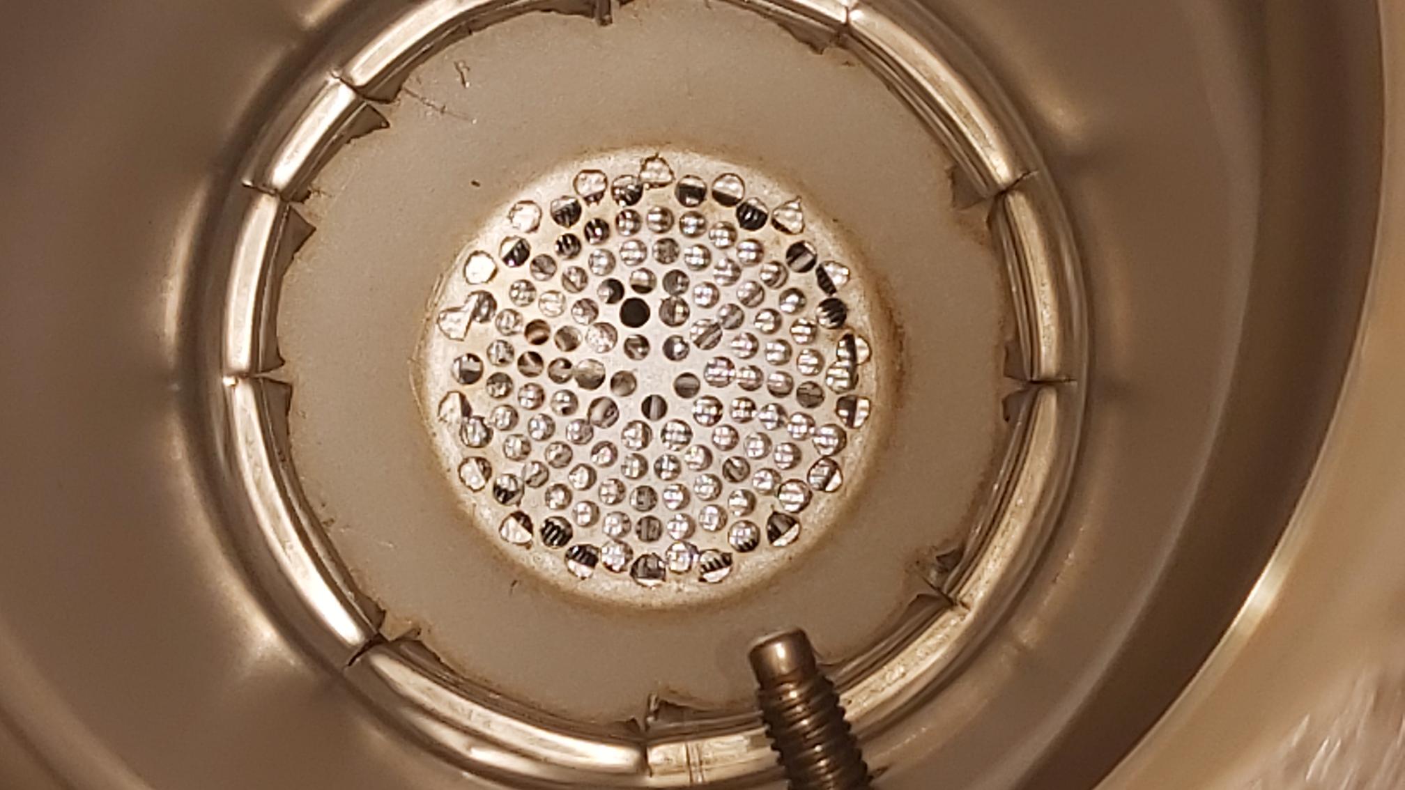
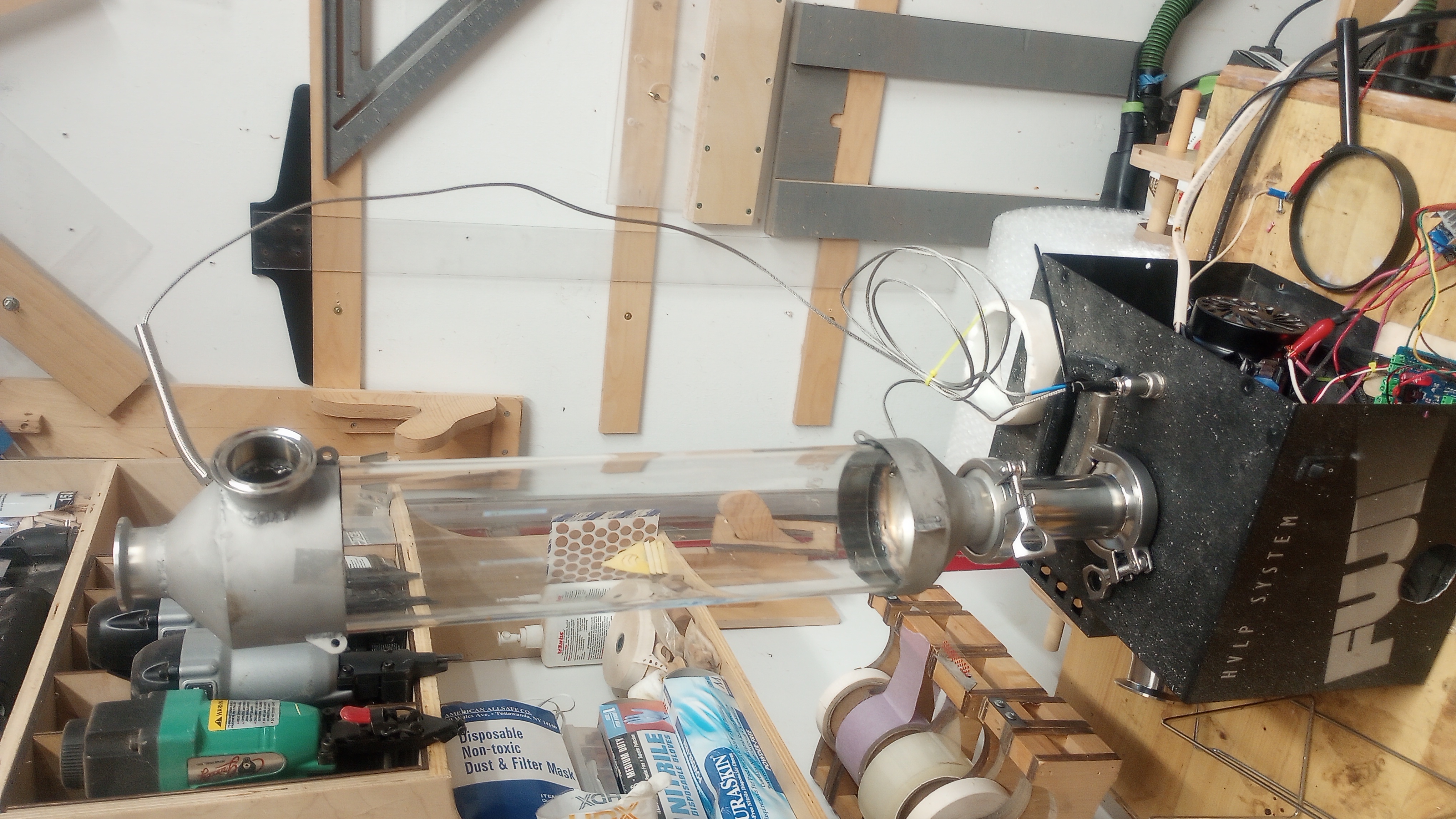
Hi All, I just built a 3300 watt fluid bed roaster. I just got my basic setup running. It's not neat and finished, but I wanted to see if the concept would work. It turned on, changed temps from Artisan and roasted.....BUT.... the airflow was not very uniform, the bean temp was pretty off and I can't control the air with artisan. SO questions. 1) I am using a free HVLP blower but it's 4-8 amps. Does anybody have a good recommendation for a motor controller I can connect to the tc4 board (Arduino) that isn't crazy expensive. UPDATE>>> I Just ordered this..Genuine RobotDYN - PWM Ac Programmable Light Dimmer 110V - 220V AC Module Controller Board for Arduino, STM, ARM, AVR, Raspberry Compatible 50/60hz with HeatSink 3.3V/5V Logic from 110V Ac to 220V AC... WILL THIS WORK ON THE TC4+ 2) The middle of my beans moved well, but they fell down the side and sat there. I know there is a lot of discussion on the holes in the screen and the layout. Any easy answers. I have a water jet and can cut any pattern. What stops the air from just running straight up the middle? 3) Bean Temp? Maybe because I was testing with a small batch so the probe was just above the beans..But should I move the probe to the side and not the center of the mass? It seems like maybe it had too much air on it so was matching the ET value more than the bean value? Suggestions. UPDATE. I just purchased a much shorter thermocouple so it will be only 1 cm in from the side. I am hoping this will get the beans more than the air. 4) Grounding. The heater is in the stainless pipe with no grounding. Should I wrap the pipe with some #12 bare wire and run it back to a ground? As you can see the stainless pipe is isolated from the blower housing by PVC. I am thinking I should wire those together? Here are some pics (I attached them as I wasn't sure how to embed them) . It's not pretty but you can see the concept. If I can solve these problems I'll build a sexy housing!! https://photos.ap...okV9vLweC7 Is there a way to put the pictures inline in the message? The picture of the beans was to see how uneven the roast was. I am assuming this is from bad airflow. I can crank up the air and get the beans flying, but it doesn't have that nice "fluid" movement. Thanks all. I LOVE THIS SITE.. Edited by hillelposner on 09/20/2023 11:50 PM |
|
|
|
| HarryDog |
Posted on 09/21/2023 8:04 AM
|
 1/2 Pounder  Posts: 349 Joined: July 20, 2022 |
Welcome hillelposner, you have a great start. I use a modified popper base and heater. For hole size I settled on 7/64" as I could drill out the stock holes a bit and still roast peaberry's if needed. Note I use a small bench blower and 3 inch chamber so I can roast 1/2 to 1 pound of green beans but the pattern is different for each. When roasting 1/2 pound it's a spray pattern and at 1 pound it's more asymmetrical so I place a small plastic lifter under the front to help the beans flow from front to back of the roaster. This is what it looked like before I drilled it out and after. My probe placement is not great for 1/2 pound and better for 1 pound. Debate on placement of probe, measuring the heat input at base of chamber or finding the right spot in your chamber to get a good read on the bean/air flow temp? One member had a 3d printed base that did find a good spot for probe placement, will look for that link. One other base I do like is the asymmetrical design where only half of the base is drilled and a plate goes up to the other side from the middle point. Some of Allenb info in post #54 https://homeroast...post_40142 This is the asymmetrical roaster in action. https://homeroast...ad_id=3174
HarryDog attached the following images:
Edited by HarryDog on 09/21/2023 10:16 AM |
|
|
|
| hillelposner |
Posted on 09/23/2023 2:00 PM
|
|
Newbie Posts: 8 Joined: March 13, 2023 |
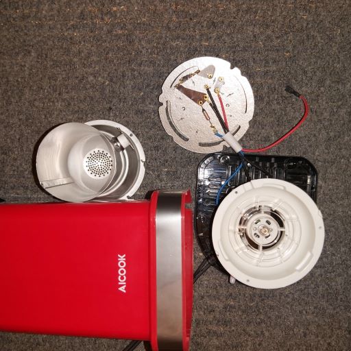
Thank you for the help with the tc placement. Now I am trying to get airspeed under control (pun intended). I just received my RobotDyn dimmer module. I am a bit confused, It has PSM, Z/C, GND, VCC (it is different than everyone else's... It doesn't say PWM, it says PSM AND there are only 3 terminals on the load / out side. I am using config_pac2.. So I put Z/C and GND in IO2 (Ground in the middle pin) Where does PSM and VCC go? The other side of the Dimmer is mains with (IN / N / OUT) In and out are hot going to the motor. I took the neutral coming in from the mains and pigtailed it, one end goes to the Dimmer the other to the motor. I also set up a 10k pot for manual control but I wasn't sure which pins on the TC4+ are the correct ones. I am assuming it's analog 1 . So does the middle of the pot go to analog 1 for the fan and analog2 for the heater...Where do the other side of the pots go? 5v and GND? When I turn it on, the blower turns on at full speed and the ZCD light turns on and flashes proportional to the way I turn the pot. But the speed doesn't change. If it helps, the fan is a HVLP bower (brushed), it draws about 9 amps at full power. I had it working fine off a router speed controller. I have the wiring diagram for the TC4, does anybody have a similar one for the TC4+ with the Robotdyn? I think I made the code adjustments. Is there anything other updating the USER file with Config_Pac2 and analog inputs? I did notice in the main sketch it says ZCD is on IO3 in the beginning comments. Is this the wrong sketch or is that overwritten with USER.H? THANK YOU SO MUCH.
hillelposner attached the following image:
Edited by hillelposner on 09/23/2023 8:45 PM |
|
|
|
| renatoa |
Posted on 09/24/2023 1:44 AM
|
|
Administrator Posts: 3104 Joined: September 30, 2016 |
PSM should be PWM... smeared paint, who knows... For TC4, let Vcc unconnected. Vcc is not mandatory to be connected, depends the output architecture of the board driving this dimmer. If open collector, have to be connected, if a generic GPIO, as TC4, not needed. Pot connections assumed correctly. ZCD is IO2 always. |
|
|
|
| hillelposner |
Posted on 09/24/2023 1:08 PM
|
|
Newbie Posts: 8 Joined: March 13, 2023 |
Thank You Renatoa!! Where does PWM go and do I have the neutral set up correct. Since there is no separate N for Load and Line (3 terminals, IN / N / Out), I am using the N for both the IN and the OUT. When I turn the pot I see the the led on the dimmer and the TC4+ change, but the blower still stays at max power. But I am still not sure where PWM from the dimmer goes. I've tried a few of the pins..D10 D09 D3 and OT2. I hope I didn't damage anything moving this around?! .....UPDATE....I just tried the dimmer with an incandescent bulb. Nothing (it stays max power). With PSM in pin 10 / VCC not connected, the TC4+ board light for IT2 flickers as I rotate the Pot which is in A0, ground and +5v (It stays ON or OFF at the extreme ends of the rotation) Here is the Dimmer I purchased. It seems different than the ones I've seen around the forum. Is that the problem https://www.amazo...ct_details Anybody know of one that may work better? Or Do I just have it set up wrong? OH... I also have a left over SSR (same as the heater one), should I try using the ZCD and the SSR with the OT2 Output???? I am so excited to see this work! ANY suggestions? Also...any suggestions on how I load pictures? I use the "attachment" and choose a file and it always says illegal file type. They are small JPGs? Edited by hillelposner on 09/24/2023 7:00 PM |
|
|
|
| greencardigan |
Posted on 09/25/2023 12:48 AM
|
 1 1/2 Pounder  Posts: 1185 Joined: November 21, 2010 |
I think there was a post somewhere here that mentioned the zero cross pulse from the Robotdyn dimmer modules is inverted compared to JimG's ZCD board that the TC4 code was originally built around. That might be contributing? Found it https://homeroast...post_75133 I'm not real familiar with the TC4+ output pin labelling, but on the TC4, Analogue input 1 typically controls the OT1 output (heater) and Analogue 2 input typically controls OT2 output (blower). Don't forget to enable the appropriate analogue input in the user.h file. Disable the other analogue input if you aren't using it. Edited by greencardigan on 09/25/2023 1:10 AM |
|
|
|
| greencardigan |
Posted on 09/25/2023 1:24 AM
|
|
1 1/2 Pounder Posts: 1185 Joined: November 21, 2010 |
Quote hillelposner wrote: But I am still not sure where PWM from the dimmer goes. I've tried a few of the pins..D10 D09 D3 and OT2. I hope I didn't damage anything moving this around?! .....UPDATE....I just tried the dimmer with an incandescent bulb. Nothing (it stays max power). With PSM in pin 10 / VCC not connected, the TC4+ board light for IT2 flickers as I rotate the Pot which is in A0, ground and +5v (It stays ON or OFF at the extreme ends of the rotation) PSM/PWM should go to a pin connected to D10. D10 should be connected to OT2. Try the pot centre pin connected to A1 or Analogue2. Analogue 2 is for the OT2 / blower control. Check mains frequency setting in user.h. |
|
|
|
| HarryDog |
Posted on 09/25/2023 5:50 AM
|
|
1/2 Pounder Posts: 349 Joined: July 20, 2022 |
Quote Also...any suggestions on how I load pictures? I use the "attachment" and choose a file and it always says illegal file type. They are small JPGs? If using an iphone the default I think is HEIC. Just keep an eye on file size if JPG, needs to be less then 10MB. I normally resize the image and email it to my PC and they are about 200KB or less. |
|
|
|
| hillelposner |
Posted on 09/26/2023 5:38 PM
|
|
Newbie Posts: 8 Joined: March 13, 2023 |
Thank you all for your responses... I think the problem is the Triac on the robotdyn is bad. I'll order a new one. In the meantime I was trying to understand how ICC burst works without a ZCD? It seems like if it's using an AC phase...it needs a reference point? Also.... if you don't have a ZCD how is it using AC off the TC4+? I feel like I am missing something obvious. I figured I would try my heater in PAC2 while waiting for the new Robotdyn dimmer. It works on Slow PWM config_PWM, but not when I change to PAC2..So I started trying to understand ICC/Burst and now I am more confused. It seems like you can do ICC burst without a ZCD in theory but in PAC2 it seems written to time off the phase control...so doesn't that need a ZCD? Where is the TC4+ getting any AC info if there isn't a ZCD? The funny thing is I started this thinking...I'll do the simplest set up. I already have an AC blower motor and housing so why not. I guess it's like boats and restaurants, roasting is a deep hole ;) AGAIN... THANK YOU TO ALL THAT ARE HELPOING ME WITH THIS.. . I love the community aspect and hopefully I'll be able to contribute at some point. I see some of you do all the heavy lifting...I hope you know you are deeply appreciated. Eureka Mignon Specialista Grinder
Profiltec 400 Espresso Machine |
|
|
|
| renatoa |
Posted on 09/27/2023 4:14 AM
|
|
Administrator Posts: 3104 Joined: September 30, 2016 |
ICC NEEDS ZCD, could be a misunderstanding if you think it does without. What theory say this ? Could be the reverse polarity issue, read again carefully the thread pointed above, it is needed a code change of the interrupt routine, to fire on falling edge instead rising, or viceversa... |
|
|
|
| btreichel |
Posted on 09/27/2023 11:37 PM
|
 1/4 Pounder  Posts: 187 Joined: May 07, 2007 |
I also noted with a zcd with an interrupt is that if a single cmd is writing to a slow device, the interrupt get pushed. I had a screen on mine and it took so long to write a single character that it got a bit tricky. |
|
|
|
| hillelposner |
Posted on 10/01/2023 10:34 PM
|
|
Newbie Posts: 8 Joined: March 13, 2023 |
I got my new RobotDyn dimmer in the mail today and still no luck. I can get zcd to work (I used a script and made a light blink based on the detection). I also hooked up a pot and used a script to make sure the pot was getting read and interpreted by the dimmer. Still no dimming of light or motor. Looking deeper into it, others have said that the new Robotdyn dimmer is not PWM anymore (which to fair, the board changed and it no longer says it's PWM, it says PSM). Using the library from Robotdyn (which was probably for the old dimmer) I couldn't even get the basic sketch to dim a light. Using serial out I could see the ZCD working and the Pot value 0-1023. I think it's time to throw in the towel on the dimmer unless somebody else has experience with this new one. If NOT... I am thinking of using it as a ZCD (since I've confirmed that part works) and then buying a separate SSR. My question on this front is how do I know if the SSR is random fire? I don't really see them listed that way. Anybody have an affordable option for a random fire SSR? (I found a used crydom d2425-10 for $18 on ebay...I'll try it)... Why are random fire so hard to find?? OR any suggestion at this point? Regarding the robotdyn. Running it by itself. I had vcc to 5v, (I tried it connected and not) gnd to gnd, ZCD on pin 2 PSM on pin 9. I defined Pin 2 as the input for ZCD, 9 as output for PSM On the other side I had "in"....AC Line in (HOT) "N" AC neutral connected to both the line in neutral and the neutral side of the Light / Fan "out" Connected to the other side of the light / fan I downloaded a basic PWM script from the examples and had chat GPT write a ZCD test script. I also copied the example from RobotDyn Website. The output was always on and at max. Edited by hillelposner on 10/02/2023 3:40 PM Eureka Mignon Specialista Grinder
Profiltec 400 Espresso Machine |
|
|
|
| hillelposner |
Posted on 12/22/2023 7:13 PM
|
|
Newbie Posts: 8 Joined: March 13, 2023 |
DONE. I got all the electronics working in both manual and with artisan. I never got the robodyn to work as a relay. Instead I used it as a zcd and bought a relay. It worked perfect. Now my problem is either too much heat or a bad perf plate. Some beans are getting supper toasty, lighting on fire and making a beautiful show inside the pyrex chamber. Any suggestions on airflow / heat / perf plate. I've tried a flat plate with holes and a fine screen made into a cone. Maybe i just need less heat? I am using a 3300 watt heater and a 1000w fan on 8 oz of beans. I designed this for 1lb loads, but am wasting a lot of money burning small batches. I can put up pictures and videos...but not sure best way to size them. Suggestions? Do I have to open each picture in corel draw (yes I still have it) and resize? Is there a way to link to a google folder? Eureka Mignon Specialista Grinder
Profiltec 400 Espresso Machine |
|
|
|
| allenb |
Posted on 12/23/2023 11:13 AM
|
 Administrator Posts: 3869 Joined: February 23, 2010 |
Quote hillelposner wrote: DONE. I got all the electronics working in both manual and with artisan. I never got the robodyn to work as a relay. Instead I used it as a zcd and bought a relay. It worked perfect. Now my problem is either too much heat or a bad perf plate. Some beans are getting supper toasty, lighting on fire and making a beautiful show inside the pyrex chamber. Any suggestions on airflow / heat / perf plate. I've tried a flat plate with holes and a fine screen made into a cone. Maybe i just need less heat? I am using a 3300 watt heater and a 1000w fan on 8 oz of beans. I designed this for 1lb loads, but am wasting a lot of money burning small batches. I can put up pictures and videos...but not sure best way to size them. Suggestions? Do I have to open each picture in corel draw (yes I still have it) and resize? Is there a way to link to a google folder? See if this helps on posting photos and vids https://homeroast...?cat_id=16 Yes, definitely more vids showing bean movment and perf plate arrangement as it is now. 1/2 lb and 1 lb drum, Siemens Sirocco fluidbed, presspot, chemex, cajun biggin brewer from the backwoods of Louisiana
|
|
|
|

| Jump to Forum: |
Powered by PHP-Fusion Copyright © 2024 PHP-Fusion Inc
Released as free software without warranties under GNU Affero GPL v3
Designed with ♥ by NetriXHosted by skpacman